5
Resistors: The Most Fundamental Component
5.1 Introduction
This chapter is about resistors, the most basic electric component.
5.2 Resistor
Resistors are the most fundamental and commonly used of all the electronic components.
Having two terminals, this component opposes current flow. This opposition is called electric resistance, measured in Ohms, and is represented by the Greek letter omega (Ω) in the SI.
5.3 Electric Resistance
All materials offer, to a certain degree, resistance to the flow of electrons. Metals, for example, offer very little electric resistance, but the resistance is there and it is not 0.
Factors like surface area, thickness, and chemical properties can alter electric resistance, and by manipulating these characteristics correctly, several types of resistors can be created.
5.4 Symbols
There are two different symbols to represent a resistor in schematics, one in the American standard and the other in the international standard. Figure 5.1 shows both symbols.
Figure 5.1 Resistor symbol (US and international standard).
Figure 5.2 Real standard resistors.
Figure 5.2 shows a picture of real resistors where color stripes describing their resistance values and other characteristics can be seen around their bodies.
5.5 Types of Resistor
There are several types of resistors produced using a variety of technologies: wire, carbon, metallic oxide film, etc.
Every type of resistor is useful for a specific application. There are resistors suitable for high stability, high voltage, high current, and high precision, among other uses.
Resistors have different degrees of precision called “tolerance.” The more precise or more suitable for a specific kind of application, the higher the cost.
General‐purpose cheaper resistors may have a tolerance of 20%, for example, meaning that a resistor of 1000 Ω, for instance, is only guaranteed to have a real resistance between 800 and 1200 Ω.
5.6 Power
Resistors are produced to handle a certain amount of current and, consequently, a certain amount of heat and power in Watts.1
Typical values for power are 1/8 W, 1/4 W, 1/2 W, 1 W, etc.
5.7 Color Code
Standard regular resistors have their characteristics encoded in four color stripes around their bodies.
The first two stripes define the first two digits of their resistance, the third represents the multiplier, and the fourth represents the tolerance. See Table 5.1.
Table 5.1 Resistor color code.
| Color | First stripe | Second stripe | Multiplier | Tolerance (%) |
| Black | 0 | × 1 | ||
| Brown | 1 | 1 | × 10 | ± 1 |
| Red | 2 | 2 | × 100 | ± 2 |
| Orange | 3 | 3 | × 1000 | |
| Yellow | 4 | 4 | × 10k | |
| Green | 5 | 5 | × 100k | ± 0.5 |
| Blue | 6 | 6 | × 1M | ± 0.25 |
| Violet | 7 | 7 | × 10M | ± 0.1 |
| Gray | 8 | 8 | × 100M | ± 0.05 |
| White | 9 | 9 | × 1G | |
| Gold | × 0.1 | ± 5 | ||
| Silver | × 0.01 | ± 10 |
A resistor with the stripes
| Brown | 1 |
| Black | 0 |
| Yellow | ×10k |
| Gold | ±5% |
will be equal to 10 × 10000 = 100 kΩ with a tolerance of ±5%.
Some types of resistors may have a fifth stripe. If so, the first three stripes represent the value, the fourth is the multiplier, and the last is the tolerance.
A resistor of this kind, with the stripes shown next, will have the following characteristics:
| Orange | 3 |
| Orange | 3 |
| Black | 0 |
| Brown | ×10 |
| Violet | ±0.1% |
The resistor will be 330 × 10 = 3.3 kΩ with a tolerance of ±0.1%.
Resistors in the range of kΩ and MΩ are also identified by using uppercase letters K and M, like 1K2 and 2M7 to identify 1.2 kΩ and 2.7 MΩ, respectively.
On the other end, the uppercase letter R is used to represent very small values of resistance. A resistor of 1.2 Ω may be referred to as 1R2.
We have compiled a table shown in Appendix B, which makes easy to find resistance values for color‐coded resistors.
Appendix G shows several tables containing the values of resistances available in the market and their tolerances.
5.8 Potentiometer
Regular resistors have two terminals and a fixed value of resistance.
Many situations in real life require resistors that can vary their resistance.
For this reason, a new kind of resistor was born: the potentiometer.
The potentiometer is basically a three‐terminal device with a central axis that can be rotated or moved to make between its terminals. The volume rotary device used in amplifiers is one example.
Symbols for the potentiometer in the American and international standards can be seen in Figure 5.3.
5.9 Trimpots
Trimpots or trimmer potentiometers are miniature potentiometers used for adjustment, tuning, and calibration in circuits.
Figure 5.3 Potentiometer symbols (US and international standard).
5.10 Practical Usage
Incandescent light bulbs are examples of resistors with a very small value of resistance.
When used in circuits, resistors are used to control the flow of current. This property can be used to protect sensitive components from excessive current.
Other uses involve dividing voltages and creating timers in conjunction with capacitors.
5.11 Electric Characteristics
Resistors are “passive components,” because they have no active role in a circuit. They simply resist current flow.
As they operate, they reduce current, and by doing so, they create an electric potential difference between their terminals. A resistor may have 10 V on one terminal and just 8 V on the other. For that reason, it is said that resistors create voltage drops across their terminals.
5.11.1 Important Facts
Obviously, voltage drops will just happen if current flows across a resistor. If current is 0, both terminals will have the same voltage.
Even without any current, resistors have what is called thermal noise, related to the internal chaotic movement of electrons inside the material’s structure. When current flows across a resistor, it creates friction against its internal structure, generating heat and increasing the thermal noise. This noise leaks to the circuit and may interfere with other components, distort signals, and create other undesired problems. Different types of resistors were created to minimize problems like this.
5.12 Resistors in Series
Resistors connected in series, like shown in Figure 5.4, will have a total resistance equal to the sum of each individual resistance, or

Figure 5.4 Resistors in series.
For an infinite number of resistors, the following formula applies.
5.13 Resistors in Parallel
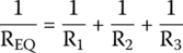
Resistors connected in parallel, like shown in Figure 5.5, will have a total resistance that can be found by the following formula:
Figure 5.5 Resistors in parallel.
If we have only two resistors, we can use this other friendly formula:
For an infinite number of resistors, we get the following formula.
5.14 DC and AC Analysis
Differently from other components we will still examine in this book, resistors are the only components that behave the same way when connected to direct current or to alternating current.
Figure 5.6 A simple resistive circuit.
Suppose we connect points A and B of the circuit shown in Figure 5.6, to a battery.
Current flows across the several components in the circuit and a certain voltage would be measured across points C and D. This voltage would be less than the one applied between A and B.
If the voltage across AB varies, voltage across CD will vary instantly.
If we replace the battery with a source of alternating voltage, the result will be the same in essence: we will measure a voltage between C and D that is less than the one applied to the input.
Again, if the voltage across AB varies, voltage across CD will vary instantly.
5.15 Input and Output Synchronism
Imagine the circuit in Figure 5.6, initially at rest. No input or output voltage.
At time equal to 0, we apply an alternating voltage at the circuit’s input and start monitoring what happens at the output. We will call t0 this instant in time.
At the time the voltage is applied across the input, a smaller voltage appears across the output.
As the input voltage varies, the output voltage also varies, at the same time, without any delay. We say that both input and output are in synchronism or in phase or have a phase equal to 0°.
In Figure 5.7 we show an input signal (larger wave) and the respective output signal (smaller wave) in synchronism.
If we want to make an analogy to the real world, we could say that resistors have zero inertia and react instantly to any variations in voltage or current.

Figure 5.7 Input and output signals in phase.
Exercises
- Consider three resistors in series: 220 Ω, 180 Ω, and 1 kΩ. What is the equivalent resistance?
- Consider three resistors in parallel: 1.2 kΩ, 100 kΩ, and 1 Ω. What is the equivalent resistance?
- Figure 5.8 shows a purely resistive circuit. What is the resistance measured between points A and B?

Figure 5.8 Resistive circuit (exercise). - A resistive circuit is connected to an alternated voltage source. What is the phase angle between output and input?
Solutions
- The equivalent resistance of resistors in series is the sum of them all.
Hence,


- The equivalent resistance of resistors in parallel is found by the formula

- Resistors R1 and R2 are in series. Their equivalent resistance (REQ1) will be the sum of their individual resistances:


The remaining resistors, R3, R4, and R5, are in parallel. Their equivalent resistance follows the formula


REQ1 and REQ2 are in series. We must sum them to obtain the total resistance between points A and B:


- Pure resistors do not affect the phase of a signal.
Note
- 1 We will talk about power in a future chapter.