11
Transformers: Not the Movie
11.1 Introduction
In this chapter, we will examine transformers, components created by combining inductors.
11.1.1 Transformers
Inductors have this name because they induce current into other elements.
Suppose we have a coil inside another one, like shown in Figure 11.1.

Figure 11.1 Two coils, one inside the other.
Both coils are electrically insulated from each other and we apply an alternating current to the first one. This first coil will develop a variable magnetic field, and because the other coil is closer, the second one will absorb part of this magnetic field and produce a variable current. In other words, without any electrical contact, the first coil produced or induced a current on the second one.
A new component was born: the transformer.
11.2 Connected by the Magnetic Field
There is no electrical connection between the primary and secondary coils. However, they are connected by the magnetic field, and they will work by mutual influence.
Like we have explained before, the magnetic field developed on the primary will induce a current in the secondary. Consequently, this secondary current will produce a magnetic field in the secondary, which will induce current on the primary and so on, ad infinitum.
The primary and the secondary will induce currents on each other and be locked in an equilibrium state. This connection between the magnetic fields is called flux linkage.
11.3 Faraday’s Law
Transformers follow Michael Faraday’s law of electromagnetic induction that states: “The rate of change of flux linkage with respect to time is directly proportional to the induced EMF in a conductor or coil.”
11.4 Primary and Secondary
The number of windings of wire on a primary and/or on a secondary of a transformer will dictate how the transformer behaves electrically.
If a transformer is composed of a primary and a secondary with 100 and 50 turns of wire, respectively, any alternating voltage applied to the primary will be reduced in half. If we apply, for example, 500 V across the primary, we will get 250 V across the secondary, because the secondary has half the turns of the primary.
The same is true the other way around: if the secondary has twice the turns of wires of the primary, the secondary voltage will be twice the voltage applied to the primary.
11.5 Real‐Life Transformer
In real life, primary and secondary coils are wounded around a rectangular ferromagnetic core with the maximum permittivity possible. This minimizes the losses and maximizes all magnetic fields (see Figure 11.2).
Figure 11.3 shows the symbol used to represent transformers with one primary and one secondary.
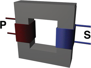
Figure 11.2 A transformer with a primary and a secondary.

Figure 11.3 Transformer symbol (one primary and one secondary).
11.6 Multiple Secondaries
Nothing prevents a transformer from having multiple secondaries, suitable to obtain multiple output voltages.
Figure 11.4 shows a diagram of a transformer with multiple secondaries, and Figure 11.5 shows its respective symbol.

Figure 11.4 A transformer with two secondaries.

Figure 11.5 Symbol used for a transformer with two secondaries.
11.7 Center Tap
There is a kind of transformer with “two secondaries” that is built by connecting, internally, the endings of the secondaries, creating something called center tap.
A center tap is a contact made to a point halfway along a winding of a transformer.
Figure 11.6 shows a transformer with two secondaries or one secondary with a center tap. These secondaries are connected internally, and a center tap secondary is derived (Figure 11.7).
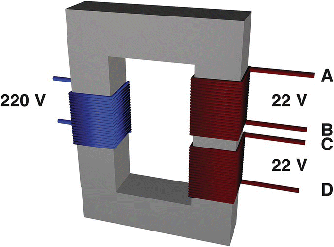
Figure 11.6 Transformer with two secondaries.
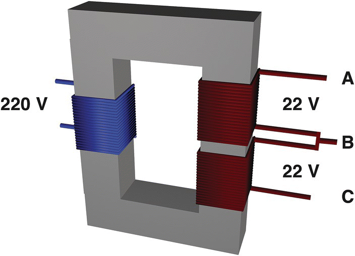
Figure 11.7 Center tap transformer.
Suppose a transformer with two 22 V secondaries like the one in Figure 11.6. Internally we connect two endings of these secondaries (points B and C), making them one point, like shown in Figure 11.7. Now, if we use point B as zero reference, we will measure 22 V between B and A and −22 V between points B and C. This is wonderful to create power supplies with negative voltages.
Figure 11.8 shows the symbol for the center tap transformer.
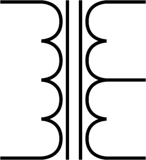
Figure 11.8 Symbol for the center tap transformer.
11.8 Law of Conservation of Energy
The law of conservation of energy states that the total energy of an isolated system remains constant. This means that energy can neither be created nor destroyed, but rather, it can only be transformed or transferred from one form to another.
Power is equal to voltage multiplied to current. Roughly speaking, if we apply a voltage of 100 V and a current of 5 A to the primary of a 2 : 1 transformer, in theory, we will be able to collect 50 V and 10 A at the secondary, because the input power will be 500 W (100 V × 5 A), must be equal to the output power, equal to 50 V multiplied by 10 A, also 500 W.
This is explained by the law of conservation of energy. The power applied to the input of that transformer must be equal to the power collected at the output. In other words, if we apply 500 W of power at the primary, we must be able to collect the same 500 W at the output. So, the product of voltage and current must be equal for the primary and secondary.
This is just a rough calculation. In real life a secondary will always deliver less power than the power applied to the primary, due to losses in the form of heat and leakage flux.
11.9 Leakage Flux
Theoretically, for a 100% efficiency, all magnetic field or flux produced by the primary should be absorbed by the secondary.
In the real world, part of the flux will not be absorbed by the secondary coils and will get lost.
This loss of magnetic field, called “leakage flux,” causes a self‐resistance of both windings, known as self‐reactance or leakage reactance. This leakage reactance causes voltage drops across the primary and secondary.
11.10 Internal Resistance
Windings are created by thousands of wounds of wire and this wire has a specific resistance per meter. That huge number of turns of wire accumulates into a reasonable electrical resistance. Therefore, transformers will also have this internal wire resistance.
11.11 Direct Current
A transformer winding will only induce current on another winding if the current alternates. Therefore, transformers will not work with direct current.
