where IP is the peak current and I is the instantaneous current.
8
Capacitors: And Electric Charges
8.1 Introduction
In this chapter, we will examine capacitors, basic electronic components very popular in all kinds of circuits.
8.2 History
The capacitor or originally known as condenser1 is a two‐terminal electric component that can store potential energy in the form of electric field.
Technically, a capacitor is composed of two metal plates, separated by a medium. This medium, called dielectric, can be any nonconductive element like air, oil, plastic, etc.
8.3 How It Works
Capacitors are basically two metal plates in parallel. The plates are put very close to each other, without touching. These plates are at rest and have roughly the same number of electrons (see Figure 8.1).

Figure 8.1 Two metallic plates in parallel, at rest.
Something magical happens when a battery is connected to the plates. Suddenly, an electric field (F) is formed between the plates, as shown in Figure 8.2.

Figure 8.2 A battery is connected between the plates.
The electric field makes the plate connected to the battery’s negative pole (A) to accumulate an excess of negative charges (electrons) and the other one to accumulate positive charges, or lack of electrons (B).
Because both plates are very close and charges with the same polarity repel each other, this excess of electrons in plate A will create a force that will repel electrons on plate B, expelling them from the plate and forcing them to migrate to the battery’s positive pole.
At this time, one may have the illusion of current flow between the plates. The truth is that the electric field generated by plate A forced electrons from plate B to move off the plate to the battery’s positive pole. No electron crossed through the dielectric from plate A to B.
As plate A receives more electrons, it saturates and an increasing repulsion force develops to prevent more electrons from arriving at plate A. The force between plates stops increasing and cannot remove electrons from the other plate anymore. At this point, current stops “flowing.”
Capacitors are normally represented on schematics by the uppercase letter C.
Figure 8.3 shows the symbols used to represent a capacitor in the American and in the international standards.
Figure 8.3 Capacitor symbols.
8.3.1 Dielectric
The kind of capacitor we are examining so far is composed of two metallic plates separated by air. Air is the dielectric.
We know that air is not a very good conductor. In fact, air is an insulator.
What makes a material a good insulator is having very few free electrons. Electrons are charge carriers. A small number of free electrons make it hard to conduct electricity, because all available electrons are held in place by the nuclear strong force, making very hard for them to move. A lot of energy would be required to strip these electrons from their positions and make them flow.
Therefore, we conclude that given enough energy an insulator can be transformed into a conductor.
Air, for example, is an insulator and a lightning is an example of how current can flow through an insulator if a colossal energy is provided. Air insulation is about 3 million volts per meter.
A unity called permittivity, measured in Farads per meter (F/m) and referred by the symbol εr or κ, denotes how much the molecules of a material oppose an external electric field. A second unity called relative permittivity, also known as dielectric constant, shows how this permittivity relates to the permittivity of the vacuum.
No current will flow across the dielectric until the electric field is strong enough to break it. If so, little “lightnings” or sparks will fly across the plates and current will flow. This is not a desired effect and will cause damage to the capacitor.
The voltage at which the dielectric breaks is called the breakdown voltage.
In real life, capacitors that can work with very high voltages are needed and air is not enough insulator for these cases. Thus, new dielectrics and construction methods had to be developed.
8.3.2 Construction Methods
Capacitors with simply round or rectangle plates parallel to each other are not practical. They are generally huge in size and have low capacitances.
One method for building better capacitors is using long two thin strips of metal foil (A and C) with dielectric material sandwiched between them (B) – everything wounded into a tight roll and sealed in paper or metal tubes – as shown in Figure 8.4.

Figure 8.4 Rolled‐up capacitors.
This method, in combination with diverse dielectrics, allows building high capacitance capacitors in a small package.
Different dielectrics also make possible to create capacitors with large capacitances, large breakdown voltages, and better performances under certain circumstances, as high frequencies, for example.
Table 8.1 shows several materials and their permittivities.
Table 8.1 Permittivity.
| Material | Permittivity (F/m) |
| Vacuum | 1 |
| Glass | 3.7–10 |
| Teflon | 2.1 |
| Polyurethane | 2.25 |
| Polyamide | 3.4 |
| Polypropylene | 2.2–2.36 |
| Polystyrene | 2.4–2.7 |
| Titanium dioxide | 86–173 |
| Strontium titanate | 310 |
| Strontium barium titanate | 500 |
| Barium titanate | 1250–10,000 |
| Diverse polymers | 1.8–10,000 |
| Calcium copper titanate | > 250,000 |
8.4 Electric Characteristics
These are the main characteristics of capacitors:
- They store electric charges in the form of an electric field.
- An ideal capacitor can store an electric charge indefinitely. In real life, they discharge slowly through the dielectric (leakage), because dielectrics are not perfect insulators and let a little bit of current flow.
- Capacitors block direct current.
- Capacitors let alternating current (AC) pass.
8.5 Electric Field
Considering that the plates of a capacitor have an area equal to A and are separated by a distance d, the electric field between the plates can be found by using the following equation.
8.6 Capacitance
Capacitance is the ratio of the change in an electric charge in a system to the corresponding change in its electric potential.
Capacitance is measured in Farads3 and represented by the uppercase letter F in the SI.
There are two kinds of capacitance: one produced by the object itself and one produced by proximity to other objects.
Any object that can be electrically charged will have its own value of capacitance.
Also, any object in the proximity of others will generate mutual capacitance.
Capacitance can also be expressed by the following formula.
8.7 Stored Energy
Capacitors can store a large amount of energy in the form of electric field in a relatively short amount of time, differently from batteries that take a long time to charge.
However, capacitors cannot supply energy or hold their electric charge for a long time because they slowly discharge through their own dielectrics or through the circuit they are connected.
However, their charge and discharge characteristics can be utilized to create very interesting circuits, like audio filters, blinkers, and timers.
The energy stored inside a capacitor can be expressed in terms of work to move charges from a plate to another. In other words, the energy stored inside a capacitor is equivalent to the work necessary to keep positive and negative charges, +q and −q, in their respective plates.
Mathematically, this work and its equivalent charge can be related by the following equation.
To find the total energy, we can integrate the previous equation:

Hence,

We know that Q = CV, and thus we can convert the previous formula into the following equation.
8.8 Voltage and Current
Like mentioned before, when a discharged capacitor is connected to a continuous voltage source, such as a battery, one of its plates will be filled with an excess of charges and the other will have a lack of charges. This excess of charges in one of the plates forms a strong electric field that expels electrons from the other plate and makes them move to the battery. Over time, the first negative plate will become saturated with charges and the process will stop.
For all intents and purposes, we can say that a current flowed through the capacitor.
8.8.1 Current on a Charging Capacitor
During the charge process of an initially discharged capacitor, the charging current will start at the maximum value possible and will exponentially decay to 0 as the capacitor charges.
Figure 8.5 shows how the current behaves during charge.
Figure 8.5 Current on a charging capacitor.
Current across a capacitor follows the following equation.
The previous equation tells us that current in a capacitor is proportional to the ratio between voltage variations over time.
We know that charge is also equal to Q = CV.
Therefore, if we derive both sides,
Upon substituting this relation in the previous formula, we obtain the following equation.
8.8.2 Voltage on a Charging Capacitor
During the charge process of an initially discharged capacitor, voltage will start at 0 and increase exponentially until it reaches the charging level. As the voltage across the capacitor approaches the charging one, the charging speed will decrease until it reaches 0 and the capacitor is fully charged.
Figure 8.6 shows how the voltage across a capacitor behaves over time in a charging capacitor.
Figure 8.6 Voltage on a charging capacitor.
Rearranging the previous equation, we see that the voltage across a capacitor can be written as
We can integrate both sides and obtain the equation of voltage across a capacitor during charge.
If we integrate for a specific interval, we get the following equation.
8.9 Examples
8.9.1 Example 1
Suppose we apply a current of 5 mA for 4 ms across an ideal 10 μF capacitor. The capacitor is initially discharged. We will call this sudden current a “current pulse.”
What is the voltage across the capacitor before and after the current pulse?
8.9.1.1 Solution
We know that integrals always calculate the area below the functions they represent.
If we want to find the voltage across a capacitor at a specific instant in time, we must consider the equation for the voltage across the capacitor during charge:

This equation describes voltage in terms of current as a function of time. In other words, this equation describes the current’s area for a specific interval.
For this example, the area is the one shown on Figure 8.7.

Figure 8.7 Current area.
8.9.1.2 Before the Pulse
Before the pulse, the capacitor is completely discharged. Hence, its voltage is 0.
8.9.1.3 During the Pulse
During the pulse, the capacitor charges exponentially and therefore its voltage increases.
Voltage across a capacitor is ruled by the following equation:
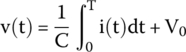
The current pulse we have applied is constant. Hence, we can substitute the function i(t) by a fixed value i and remove it from the integral. Also, V0 is equal to 0, because the capacitor is initially discharged.
Upon substituting these values, we get

Solving the integral,

Upon substituting the values in the formula, we obtain the voltage across the capacitor after 4 ms:

8.9.1.4 After the Pulse
After the pulse, current drops to 0 and the capacitor stops charging.
An ideal capacitor will never discharge and hold its charge indefinitely.
Consequently, the capacitor will keep its voltage equal to 2 V forever.
8.9.2 Example 2
We repeat the same example as before but using a 1000 μF capacitor.
What is the voltage across the capacitor after the same current pulse is applied?
8.9.2.1 Solution
Upon substituting the values in the formula, we obtain the voltage across the capacitor after 4 ms:
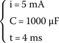
For the same pulse, the voltage across the capacitor is very small now. This is expected because the capacitance is bigger and, for that reason, the capacitor takes more time to charge.
8.10 AC Analysis
We will examine, now, what happens when a capacitor is connected to an AC source.
Capacitors have the property to block direct current and let pass AC under certain conditions.
Capacitors react when subjected to AC by offering a resistance to the current flow. This resistance, known as reactance, varies with the wave’s frequency. This property can be used to create filters and manipulate, for example, audio4 signals.
8.10.1 Pool Effect
Some of the properties of capacitors can be explained by an analogy with pools.
Imagine an empty pool with two pipes. One of the pipes feeds the pool with water and the other drains the water out. The input pipe is larger and is always closed. It opens, when necessary, to let water in. The output pipe is thin and is always open, letting water out, continuously.
If the pool is empty and we let water in, it will take a while to fill. The time it takes to fill depends on how much water enters the pool per second and the size of the pool.
If the pool is full and we close the input pipe, the pool will continue to hold its level of water for a while but the water level will decrease slowly, because the output pipe is draining the pool.
If the pool is half full and the water flow at the input pipe starts to fail or variate dramatically, the output flux will not be affected and continue to flow as before. We conclude that the pool creates a kind of buffer or cushion effect, keeping the output flow stabilized. Looking through another point of view, we can say that the pool resists drastic changes in the input flow of water, a kind of inertia that will “smooth” drastic changes.
Capacitors have the same behavior. As soon as a voltage is applied, they will start to charge. If the voltage increases beyond the capacitor current level, it will charge to match the input level. If the input voltage decreases, the capacitor will discharge to match the input level. If the input voltage is removed, the capacitor will keep its charge for a while but will slowly discharge.
Sudden and drastic variations of the input voltage will be softened and damped, and the voltage across the capacitor will remain relatively constant.
8.11 Capacitive Reactance
Capacitors resist to any sudden changes in voltage. This resistance is called capacitive reactance, represented, normally, by the symbol Xc and measured in Ohms (Ω).
Capacitive reactance is represented by the following formula.
or by
considering that ω = 2πf.
Capacitive reactance and frequency are inversely proportional; if frequency increases, the reactance decreases.
If frequency reduces gradually toward 0,5 capacitive reactance will skyrocket to infinity. This explains why capacitors block direct current.6
8.12 Phase
Like explained before, capacitors resist sudden changes in voltage. This resistance represents a kind of inertia that prevents capacitors from reacting instantly to voltage changes.
When a capacitor starts to charge, current will be maximum and voltage minimum. When the capacitor is charged, voltage will be maximum and current will be 0.
It is clear the existence of a delay between voltage and current and that voltage is 90° behind current.
Technically speaking, voltage and current are 90° out of phase.
8.12.1 Mathematical Proof
Like examined before, the voltage across a capacitor can be described in terms of current by this formula:
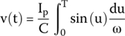
If we apply an alternated current across a capacitor, this current follows a sinusoidal form:
Substituting (8.3) in (8.2), we get
To solve this integral we must use the substitution rule.
Hence,
Substituting this on the integral,

By applying the previous concept, we get
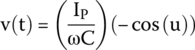
By applying this other concept, we obtain the final equation for the voltage across a capacitor.
What do we see when we compare equations (8.3) and (8.5)?
We see that the first equation describes current in terms of sin(ωt) and the second describes the voltage in terms of sin(ωt − π/2).
The voltage equation is telling us to subtract π/2, equivalent to 90°, to the angle, meaning that the voltage is delayed 90° in relation to current.
Figure 8.8 shows a diagram of voltage curve (second curve) that is 90° behind the current curve (first curve).
Figure 8.8 Voltage (in black) is behind current (in red).
8.13 Electrolytic Capacitor
To increase the capacitance of a capacitor, we can do a few things:
- Increase the plate areas, but this is not practical and will make capacitors huge.
- Create new dielectrics that can increase the capacitance by increasing the insulation between the plates.
- Reduce the distance between the plates, but this is a problem, because the distance between the plates depends on how thin we can make the dielectric.
To overcome these problems, a new kind of capacitor was invented, called electrolyte capacitor, where the plates are formed by an aluminum foil with an oxide layer, a tissue soaked in electrolyte liquid, and a regular aluminum foil.
The oxide layer on the first aluminum foil insulates it from the electrolyte liquid, becoming the dielectric and making the electrolyte liquid itself the other “plate,” a kind of virtual plate.
For that reason, the electrolyte capacitor is not formed by two metal plates, but rather by an oxidized metal plate and an electrolyte element. The oxidized layer serves as a dielectric and the second regular aluminum foil serves just to supply voltage to the electrolyte.
Therefore, an electrolyte capacitor is composed of a metal foil (A) with an aluminum oxide layer (B), a tissue soaked in electrolyte liquid (C), and a regular metal foil (D), as shown in Figure 8.9.

Figure 8.9 Several layers of an electrolyte capacitor (cross section).
The electrolyte capacitor is far from being a traditional capacitor. In fact, the process that creates the oxide layer on one of the plates makes the electrolyte capacitor only able to conduct current in one direction. If an electrolyte capacitor is subjected to a reverse current flow, it will be destroyed and probably explode.
Therefore, these electrolyte capacitors, also known as “polarized capacitors,” have a minus sign on their bodies to identify their polarity.
The advantages of electrolytic capacitors are as follows:
- Their dielectric layer is very thin, allowing the plates to be very close, thus increasing the capacitance.
- They are extremely tough, have a high degree of insulation, and can heal themselves up to a certain degree during their lifespan.
- High capacitance electrolyte capacitors have very small sizes.
- Very cheap to produce.
Figure 8.10 shows a representation of an electrolytic capacitor where a huge minus sign can be seen on the stripe and an X is seen on the metallic end.
Figure 8.10 A radial electrolyte capacitor.
This X at ending is, in fact, a groove to create a weakened part of the casing, which will bulge upward and help the capacitor release its contents in case of failure. If so, they will not explode violently hurting people or causing damage to the whole equipment. These grooves are designed to prevent catastrophic failures from happening.
Figure 8.11 shows the symbols for the electrolytic capacitor in the United States (first symbol) and in the world (last two symbols).

Figure 8.11 Electrolyte capacitor symbols in the United States and internationally.
8.14 Variable Capacitors
Some applications in the real world require capacitors that can have a variable capacitance. For that reason, a new capacitor was born, the variable capacitors or trimmers.
The first line in Figure 8.12 shows the symbols for the variable capacitors used in the United States, and the second line shows the symbols used internationally.

Figure 8.12 Variable capacitors.
8.15 Capacitors in Series
If we connect two capacitors in series, like shown in Figure 8.13, the equivalent capacitance between points A and B can be found by using the following formula:

Figure 8.13 Capacitors in series.
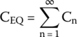
For an infinite number of capacitors, a more generic formula must be used.
If there are just two capacitors in series, a friendlier formula can be used:
8.16 Capacitors in Parallel
If we connect two capacitors in parallel, like shown in Figure 8.14, the equivalent capacitance between points A and B can be found by using the following formula:
For an infinite number of capacitors, a more generic formula must be used.
Figure 8.14 Capacitors in parallel.
8.17 Capacitor Color Code
In the past, capacitors, as well as resistors, were identified by a color code painted on their bodies. Today this is not the case anymore.
However, it is worth to know how this code works because it is not rare to find capacitors like that on old equipment.
8.17.1 The Code
The code was composed of four or five stripes painted on their bodies.
The capacitance is represented by the four‐color code: the first two stripes represent the first digits, the third stripe is the multiplier, and the last stripe is the maximum operational voltage.
In the five‐color code, the first two stripes represent the first two digits, the third stripe is the multiplier, the fourth stripe represents the tolerance, and the last one represents maximum operational voltage (Figure 8.15).
Figure 8.15 Four‐ and five‐stripe capacitors.
Table 8.2 shows the values for each stripe in both codes.
A capacitor with the stripes shown next will have the following value:
| Brown | 1 |
| Black | 0 |
| Orange | ×1000 |
| Brown | ±1% |
The first three colors mean 10 × 1000 pF or 10000 pF, which is equivalent to 10 nF.
Table 8.2 Capacitor color code.
| Color | First Stripe | Second Stripe | Multiplier | Tolerance >10 pF (%) | Tolerance <10 pF |
| Black | 0 | 0 | ×1 | ±20 | ±2 pF |
| Brown | 1 | 1 | ×10 | ±1 | ±0.1 pF |
| Red | 2 | 2 | ×100 | ±2 | ±0.25 pF |
| Orange | 3 | 3 | ×1000 | ±3 | |
| Yellow | 4 | 4 | ×10k | ±4 | |
| Green | 5 | 5 | ×100k | ±5 | ±0.5 pF |
| Blue | 6 | 6 | ×1M | +80, –20 | |
| Violet | 7 | 7 | ±10 | ±1 pF | |
| Gray | 8 | 8 | ×0.01 | ±5 | |
| White | 9 | 9 | ×0.1 | ±10 | |
| Gold | ×0.1 | ||||
| Silver | ×0.01 |
The last strip is the tolerance, equal to ±1%, because the capacitor is bigger than 10 pF.
Therefore, the capacitor is 10 nF ± 1% of tolerance.
8.18 Capacitor Markings
Modern capacitors use a numeric code to identify themselves like 473 J or 104 K.
The first two digits represent the capacitance, the third is the multiplier, and the letter is the tolerance.
Tables 8.3 and 8.4 show the multipliers and the tolerances.
Therefore, a capacitor marked as 473 J will be equal to 47 × 1000 pf = 47000 pf or 47 nF, and the J letter would be a tolerance of ±5%.
Capacitor will be 47 nF ± 5% tolerance.
Some capacitors may contain additional numeric codes, written apart from the main code, to represent their maximum operational voltage. Table 8.5 shows these codes.
Appendix H lists several types of capacitors produced worldwide.
Table 8.3 Multipliers.
| Third digit | Multiplier |
| 0 | ×1 |
| 1 | ×10 |
| 2 | ×100 |
| 3 | ×1k |
| 4 | × 10 k |
| 5 | × 100 k |
| 6 | × 1 M |
| 7 | |
| 8 | ×0.01 |
| 9 | ×0.1 |
Table 8.4 Tolerance.
| Letter | Tolerance <10 pF |
| B | ±0.1 pF |
| C | ±0.25 pF |
| D | ±0.5 pF |
| F | ±1% |
| H | ±2% |
| G | ±3% |
| J | ±5% |
| K | ±10% |
| M | ±20% |
| P | +100%, –0% |
| Z | +80%, –20% |
Table 8.5 Additional numeric codes.
| Code | Voltage (V) | Code | Voltage (V) |
| 0G | 4 | 2C | 160 |
| 0L | 5.5 | 2Z | 180 |
| 0J | 6.3 | 2D | 200 |
| 1A | 10 | 2P | 220 |
| 1C | 16 | 2E | 250 |
| 1E | 25 | 2F | 315 |
| 1H | 50 | 2V | 350 |
| 1J | 63 | 2G | 400 |
| 1K | 80 | 2W | 450 |
| 2A | 100 | 2H | 500 |
| 2Q | 110 | 2J | 630 |
| 2B | 125 | 3A | 1000 |
Exercises
- A capacitor with an area equal to 10 mm2, a distance between plates equal to 2 mm, and a dielectric permittivity of 2.1 F/m has a charge of 1 C. Find the electric field intensity.
- A voltage of 80 V is measured across a 100 μF capacitor. Find the stored charge.
- A 11 μF capacitor has a charge of 22 C. What is the total stored energy?
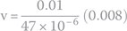
- An initially discharged 47 μF capacitor receives a current pulse of 10 mA for 8 ms. What voltage develops across its terminals after that time?
- What is the total capacitance of three capacitors, 47 μF, 100 μF, and 330 μF, connected in series?
- What is the total capacitance of three capacitors, 47 μF, 100 μF, and 330 μF, connected in parallel?
- An alternating voltage with a frequency equal to 300 Hz is applied to a 200 μF capacitor. What is the capacitor’s reactive capacitance?
- A capacitor has the markings 104Z on its body. What capacitor is that?
Solutions
- The electric field is calculated by the following formula:

Substituting the values, we have
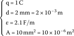
on the formula

- The following formula relates charge and voltage for a given capacitance:

Substituting the values, we get

- The energy formula that relates charge and capacitance is

Upon substituting the values, we obtain the total stored energy:

- The capacitor was initially discharged. During the current pulse the capacitor starts to charge and develops a voltage across its terminals.
Capacitor’s voltage equation, in terms of current, is

The current pulse is constant. We can remove it from the integral.
The capacitor is initially discharged; thus,

Hence, our integral is now

Using this concept, we can solve the integral:

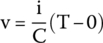

If we use the values, we have

We get the voltage across the capacitor after the pulse:
- Series capacitance is calculated by the following formula:

For this current example, we get


- Parallel capacitance is calculated by the following formula:
For this current example, we get

- Reactive capacitance is given by the formula

Substituting the values, we have

- Code 104Z means 10 followed by 4 zeros. The answer expressed in picofarads, meaning 100000 pF or 100 nF.
Letter Z means a tolerance between −20% and +80%.
Therefore, the result is shown below.
Due to the tolerance range, the capacitor can have any value from 80 to 180 nF.
Notes
- 1 The term condenser used to refer to capacitors was first used around 1782. It is interesting to know that, in that year, James Watt had just patented a new revolutionary component for his steam engine, called the “separate condenser,” making the term a success among scientists.
- 2 Leyden Jar (or Leiden Jar) is a kind of primitive capacitor that can store high voltage electric charges between two electric conductors. Invented by accident in 1746 by Pieter van Musschenbroek.
- 3 In honor of Michael Faraday (1791–1867), an English scientist that pioneered the first studies about electromagnetism and electrochemistry.
- 4 Yes, audio is an alternating voltage/current.
- 5 Remember limits.
- 6 Direct current is a kind of alternating current with a frequency equal to 0.
..................Content has been hidden....................
You can't read the all page of ebook, please click here login for view all page.