By substituting this in (28.1), we get
28
RLC Circuits: Part 2: Current Analysis in Circuits Containing Resistors, Capacitors, and Inductors in Series
28.1 Introduction
In the last chapter, we have performed a voltage analysis in RLC series circuits, finding their voltage equations for various specific cases.
In this chapter we will continue to examine series RLC circuits in terms of current analysis.
28.2 The Circuit
Our analysis will focus on the same circuit we have used on the last chapter: a direct voltage source, a resistor, a capacitor, an inductor, and a switch in series, like shown in Figure 28.1.

Figure 28.1 A basic RLC circuit.
Like before, the switch is initially open, there is no current flowing in the circuit, the inductor is completely de‐energized, and the capacitor is completely discharged.
At time t = 0 s, the switch is closed, and current flows and reaches the inductor.
28.2.1 Current
As soon as the switch is closed, we can apply to the circuit. Kirchhoff’s voltage law (KVL) states that the sum of all voltages in a closed loop is 0.
Therefore, the power supply voltage (V1) is equal to the voltage drop on the resistor added to the voltage across the inductor and capacitor, or
Voltages across a capacitor, an inductor, and a resistor are defined as
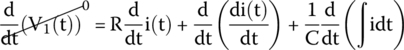
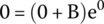
If we take the derivative of both sides of this equation with respect to time, we obtain

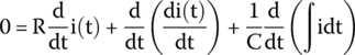
V1(t) is the power supply voltage, a constant. We know that the derivative of a constant is 0; therefore,
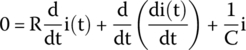
The last term is the derivative of an integral, that is, one thing cancels the other, and we have just the function.
Therefore,
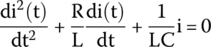
or after rearranging the equation, we have
or written in standard form:
This second‐order differential equation for the current (28.2) is, obviously, very similar to the one described on the previous chapter for voltage across a capacitor.
For the same reasons as before, we know that the transient equation for the current will have the form
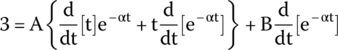
Consequently, we can convert Eq. (28.2) into
The first two terms are derivative of exponentials that we already know how to solve, which will produce the following result for the first term and for the second term:
and
By putting these terms back into Eq. (28.3), we get
Equation (28.4) is the same we have found for the voltage across the capacitor in the previous chapter.
Consequently, we know that this equation will have three possible solutions for the current: critically damped, overdamped, and underdamped.
28.3 Current Equations
There is no need to repeat the same calculation we have done in the last chapter.
The final equations for the three cases will be the following.
28.3.1 Critically Damped Solution
28.3.1.1 Current Curve
Figure 28.2 shows the curve for the current flowing in the critically damped series RLC circuit, as soon as the switch is closed.
Figure 28.2 Current flowing in the circuit (critically damped solution).
Notice how the current grows from 0 and hits a peak on the positive side and then decays slowly to 0.
28.3.2 Overdamped Solution
28.3.2.1 Current Curve
Figure 28.3 shows the curve for the current flowing in the overdamped series RLC circuit, as soon as the switch is closed.

Figure 28.3 Current flowing in the circuit (overdamped solution).
Notice how the current grows fast from 0 and hits a peak on the positive side and then decays exponentially slowly to 0.
28.3.3 Underdamped Solution
28.3.3.1 Current Curve
Figure 28.4 shows the curve for the current flowing in the underdamped series RLC circuit, as soon as the switch is closed.
Figure 28.4 Current flowing in the circuit (underdamped solution).
Notice how the current oscillates from positive to negative values until it dies.
The amplitude decays according to an exponential pattern.
28.4 Examples
28.4.1 Example 1
Figure 28.5 shows a circuit with a direct voltage source, a switch, a resistor, an inductor, and a capacitor in series.

Figure 28.5 A basic RLC circuit.
The switch is open, there is no current flowing in the circuit, the inductor is completely de‐energized, and the capacitor is completely discharged.
At time t = 0 s, the switch is closed, and current flows and reaches the inductor.
The following is what we want to find about the circuit:
- What is the current across the circuit after the switch is closed?
- What is the current across the circuit two seconds after the switch is closed?
28.4.1.1 What Is the Current Across the Circuit After the Switch Is Closed?
When the switch is closed, current flows and reaches the inductor. The inductor hates sudden variations of current and will prevent current from flowing as soon as the switch is closed.
28.4.1.2 What Is the Current Across the Circuit Two Seconds After the Switch Is Closed?
To find the current equation for this circuit, we must find several parameters and coefficients like α, ω0, and ωd. This circuit is the same used in last chapter, and, therefore, the values are already known as

This is an underdamped circuit because α < ω0; therefore, the current equation has the form
Upon substituting the values, we get
To find K1 and K2, we must apply the initial conditions for the circuit.
28.4.1.2.1 First Condition: Current at Time Zero
To find the first constant, we must take equation (28.6) and solve for t = 0 s:
28.4.1.2.2 Second Condition: The Derivative of the Current Equation for Time Zero
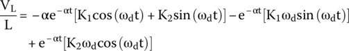
To find the other constant, we take the derivative of equation (28.5) with respect to time and solve for t = 0 s.
Therefore, we take the current equation
and take the derivative
The first term is the derivative of current with respect to time and we know that the voltage across an inductor is equal, exactly, to the derivative of current with respect to time multiplied by the inductance, or
Therefore,
We can substitute this relation in the equation
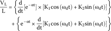
We are before a derivative of a product of functions (u and v) and we can use the product rule:
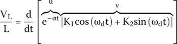
Therefore, the derivatives will expand to
that can be expanded to
Equation (28.8) has three derivative terms.
The first term is the derivative of an exponential and will produce the following result:
The second term is the derivative of a cosine.
Therefore, this produces the following result:
The third term is the derivative of a sine.
Therefore, this produces the following result:
By putting terms (28.9), (28.10), and (28.11) together in Eq. (28.8), we obtain
Rewriting

Substituting the K1 that we have found in (28.7), we get

As soon as the switch is closed, no current crosses the inductor because it generates an electromotive force to block the flow of current. This electromotive force is equal to the power supply voltage. Therefore, the voltage across the inductor VL, the moment the switch is closed, is equal to V1.
Therefore, upon substituting the known values on the equation
we get
Solving for t = 0 s
We can now assemble the final equation as
The current for t = 2 s is
28.4.2 Example 2
Consider the same circuit shown in Figure 28.5 in the previous example with two changes: the resistor is an 8 Ω, instead of 0.1 Ω, and the power supply is a 10 V direct voltage source, instead of 12 V.
This new circuit is ruled by the following second‐order differential equation:
Find the equation for the current that rules this circuit.
28.4.2.1 Solution
We divide the circuit’s equation by two to rewrite it using the standard form:
Series RLC circuits follow second‐order differential equations in the form
By comparing these two equations, we can extract the following information:
We get L by substituting R = 8 Ω:
We can also extract
Therefore, we obtain C:
Using the values of R, L, and C, we can obtain
Because α > ω0, this is an overdamped series RLC circuit, and the current equation follows the form
To find A and B, we apply the initial conditions.
28.4.2.1.1 First Condition: Solve the Current Equation for t = 0 s
We take equation (28.12) and solve for t = 0 s:
28.4.2.1.2 Second Condition: Take the Derivative of the Current Equation and Solve for t = 0 s
If we take the derivative of the current equation (28.12), we get
The first term is the derivative of current equation with respect to time.
But we know that the voltage across the inductor is equal to
If we rearrange (28.14), we can write it as the derivative of current with respect to time:
which we can substitute in (28.13), making it like
The voltage across the inductor, or VL, is the voltage across the inductor immediately after the switch is closed, which is known to be the same voltage as the power supply, as explained before.
Therefore, the equation can be converted into
Solving for t = 0 s,
We know that A = − B; therefore,
To find m1 and m2, we must find the equation roots:
which is equal to
and we can find its roots by using the quadratic equation:
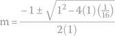
Therefore, m1 is
and m2 is
Therefore,
and A will be
Finally, the equation can be written as follows.
Exercises
- Figure 28.6 shows a circuit like the one we have been analyzing in this chapter, a resistor, an inductor, a capacitor, and a switch in series with a direct voltage power supply.
Figure 28.6 A basic RLC circuit.
The switch is initially open, the inductor is completely de‐energized, and the capacitor is completely discharged.
The circuit’s components have the following values:
At time t = 0 s, the switch is closed, and current flows and reaches the inductor.
The following is what we want to find about the circuit:
- What is the current flowing in the circuit as soon as the switch is closed?
- What is the current flowing in the circuit 10 ms after the switch is closed?
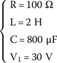
- Consider a series RLC circuit like the previous one. The values of L and C are unknown but the resistor R = 1 Ω and the power supply V1 = 30 V.
This circuit is ruled by the following equation:
We know that the current is 0 for t = 0 s.
In t = 0 s, the switch is closed.
Find the current equation and its value for t = 1 ms.
Solutions
What is the current flowing in the circuit as soon as the switch is closed?
After the switch is closed, current flows and reaches the inductor. The inductor hates sudden current variations and will not let this new current pass.
What is the current flowing in the circuit 5 ms after the switch is closed?
We can have three kinds of series RLC circuits, namely, critically damped, overdamped, and underdamped, each one with its own equations for the current.
The first thing we need to do is to know which circuit is this one.
The given values are

We first calculate α and ωo:


We see that α = ω0, equivalent to a critically damped circuit.
The equation for the current, for this case, is
To find A and B, we apply the circuit’s initial conditions.
First Condition: Solve the Current Equation for t = 0 s.
Here we go:
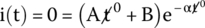
Second Condition: Take the Derivative of the Current Equation and Solve for t = 0 s.
We take the derivative of the current equation


Voltage across the inductor is

Therefore,

where VL is the voltage across the inductor as the switch is closed, which is known to be equal to the power supply voltage, as explained before.
Therefore,


We are before the derivative of a product of functions and we can use the product rule:
Therefore,
We already know how to solve the derivative of an exponential; therefore,


By substituting B = 0, we get

Solving for t = 0 s,

Thus, we can write the final current equation as follows.
The current for t = 10 ms is

- We must find the values of L and C.
First, we take the circuit’s second‐order differential equation and divide it by 400 to write it in the standard form:
The result is

Series RLC circuits are ruled by second‐order differential equations in the general form:
By comparing this equation with the original in the standard form, we can extract the following values:

By substituting R = 1 Ω, we get,
Another value we can extract is

Therefore,
Knowing R, L, and C, we can find other parameters:


We see that α = ω0, equivalent to a critically damped circuit.
The equation for the current, for this case, is
To find A and B, we apply the circuit’s initial conditions.
First Condition: Solve the Current Equation for t = 0 s.

Second Condition: Take the Derivative of the Current Equation and Solve for t = 0 s.
Like we did in the previous example, we take the derivative of the current equation and will get to the following point:
VL is the voltage across the inductor as the switch is closed, known to be the same as the power supply.
Therefore,


In the last example, we already explained how to solve this:

Solving for t = 0 s,

By substituting B = 0,
Therefore, the final current for the equation can be written as follows.
Current for t = 1 ms is

..................Content has been hidden....................
You can't read the all page of ebook, please click here login for view all page.