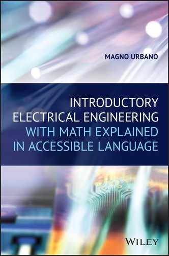
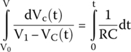
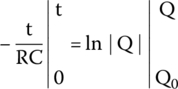
First integral goes from the capacitor’s voltage at time equal to 0 (V0) to a generic voltage V at time is equal to t. Second integral goes from 0 to the same time t.
25
RC Circuits: Voltage and Current Analysis in Circuits Containing Resistors and Capacitors in Series
25.1 Introduction
In this chapter, we will examine the concepts behind resistor–capacitor series circuits, known as RC circuits.
As explained in previous chapters, when a voltage is applied to a completely discharged capacitor, it makes the capacitor charge exponentially to the power supply voltage. As it happens, current will decrease, also exponentially, to 0.
25.2 Charging a Capacitor
Consider the circuit shown on Figure 25.1, composed of a resistor and a capacitor in series with a switch and a power supply. The switch is initially open, so the circuit is not working. The capacitor is completely discharged.

Figure 25.1 RC circuit and an open switch.
At time t = 0 s, the switch is closed. Current starts flowing from the power supply through the resistor R and reaches the capacitor. The capacitor starts to charge.
Current is at its maximum value, just limited by the resistor. As charging starts, the capacitor is seen, by the circuit, as a wire, a short circuit, because it makes no opposition to the current flow.
As time passes and the capacitor charges, current will exponentially decrease to 0, and voltage across the capacitor exponentially increases to the power supply voltage. Variations of current and voltage will then stop and the circuit will stabilize.
25.2.1 Charging Voltage
By applying nodal analysis to node A, in the circuit shown in Figure 25.1, we get the following current for the circuit’s current:
However, as defined in this book before, current across a capacitor (iC) is defined as
The resistor and the capacitor are in series, so current flowing across one is the same as the current flowing across the other. Therefore, we can equate (25.1) and (25.2):
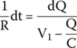
Rearranging the equation,

Integrating both sides,

We can compare the first integral to the following math concept.
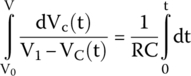
Compared to this math concept, the first integral

has

The negative sign of “a” will produce a negative result for the natural log part.
For the other integral, we have the following math concept.
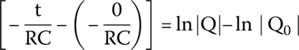
By applying this concept to the second integral and putting it all back together, we get
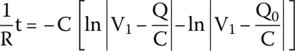
Multiplying both sides by −1,
Therefore,

We can get rid of the natural logarithm by applying the following rule.
By applying this rule, we get
By passing V1 to the other side,
and by multiplying both sides by −1, we get the final equation for the voltage across the capacitor during the charge period.
25.2.2 Charge Equation
Charge and voltage across a capacitor have a direct relation through the formula Q = CV.
Hence, the charge equation can be obtained by multiplying the voltage equation by C.
The same result can be obtained by using Kirchhoff’s voltage law (KVL).
KVL states that the sum of the electric potential differences (voltages) around any closed network is 0, or
It is known that the voltage drop across the resistor is given by its resistance multiplied by the current, or
and that the voltage across capacitor is equal to the charge divided by capacitance:
By substituting VR and VC in equation (25.4), we get
Current that flows across the capacitor is the same that flows across the resistor and is equal to the ratio between charge over time, or
If we substitute i in the KVL equation, we obtain
We organize the equation in a different way:
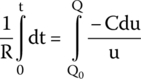
and integrating both sides,
To solve the second integral, we use the integral substitution rule:
Let
Therefore,


Therefore,

Upon substituting u and dQ in the main equation, we get
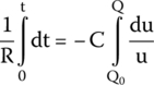
By applying this concept, we get
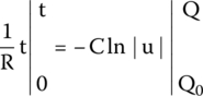
After solving the integrals for the defined ranges, we get
Multiplying both sides by −1/C,

Therefore,

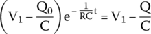
We can get rid of the natural logarithm by applying the following rule.
Therefore,


By rearranging the equation
and by multiplying both sides by −1, we get the final equation that is, obviously, identical to the one in (25.3):
25.2.3 Charging Current
We have just obtained the charge equation as
But we know that current is defined as the ratio of charge over time, or in other words the derivative of charge with respect to time, or
That is the exact definition of derivative, or in this case the derivative of charge with respect to time.
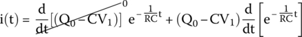
Therefore, current will be the derivative of the charge equation with respect to time:

We can expand the derivative by using the following concept.
Therefore,

Hence,
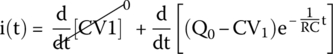

We get a result that is equal to a derivative of a product of two functions, (Q0 − CV1) and ![]() .
.
This can be solved by applying the following mathematical concept.
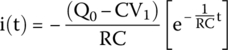
By applying this rule, we get
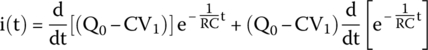
Therefore,

Thus,
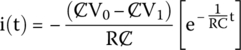
Charge, voltage, and capacitance are related by Q = CV.
Therefore, upon substituting this relationship in the previous formula, we get

By simplifying,
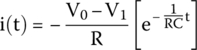
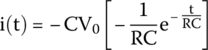
Hence, after rearranging, we get the final equation for the charging current through the capacitor.
25.3 RC Time Constant
The RC time constant is the time required to charge a capacitor through a resistor, from an initial charge of 0–63.2% of the value of an applied DC voltage or for a discharging capacitor to lose 63.2% of its initial charge.
This value is derived from the mathematical formulas of charge and discharge for the capacitor.
The RC time constant, also called tau (τ) and measured in seconds, is equal to the product of the circuit resistance in Ohms and the circuit capacitance in Farads.
25.3.1.1 Transient and Steady States
The period of time in which an RC circuit exhibits variation of current and voltage, after a voltage pulse is applied to it, is called transient phase.
After the transient phase is over, the circuit stabilizes and will not exhibit any other variations. The stable phase is called steady state.
25.3.1.1.1 How Long Does the Transient Phase Last?
When a capacitor charges, the amount of charge increases following an exponential curve. For this reason, the ratio of charge decreases with time. Hence, an infinite amount of time is required to reach the maximum charge.
In practice, engineers cannot wait indefinitely for a capacitor to charge. In electrical engineering, a capacitor is considered charged after a time equal to five time constants.
This happens because after each time constant, the voltage or charge will raise or decay according to the following table.
| RC time constant interval | Percentage of total voltage (%) |
| 1???? | 62.3 |
| 2???? | 86.5 |
| 3???? | 95.0 |
| 4???? | 98.2 |
| 5???? | 99.3 |
The table shows that after five time constants, the voltage of a charging capacitor will be 99.3% of the charging value or the voltage of a discharging capacitor will have decayed by the same amount, which is reason why five time constants is the number chosen to represent a fully charged/discharged capacitor.
25.3.2 General Formula
Suppose the capacitor on Figure has an initial charge and, consequently, an initial voltage (V0) before the switch is turned on. When the switch is closed, the capacitor will start charging, not from 0 but from its initial voltage to the power supply voltage.1
Because it takes an infinite time for the capacitor to charge to the power supply’s voltage, this voltage at infinite time is called V∞ or steady‐state voltage.
The formulas we have described so far are represented on the international literature, as shown below.
25.3.3 Discharging a Capacitor
Figure 25.2 shows a DC power supply, a resistor, a capacitor, and a two‐position switch.

Figure 25.2 RC circuit initially working.
In the following circuit, the switch has been sitting for a long time, connecting points A and B.
The resistor R and the capacitor C have been connected to a constant voltage source, V1, for a long time. The circuit is, therefore, on the steady‐state phase, the capacitor is completely charged, and no current is flowing in the circuit anymore.
At time t = 0 s, the switch is moved from position AB to AC, disconnecting the resistor and the capacitor from the power supply and connecting them in parallel.
The capacitor has now a path to discharge and will do it slowly through the resistor.
25.3.3.1 Charge During Discharge
A capacitor will always discharge following an exponential curve.
During discharge, voltage, current, and charge all decay from their initial values to a lower ones following an exponential curve. This phase where current, charge, and voltage vary is called transient phase.
25.3.3.1.1 Considerations
Circuits with transient phases will always have equations for voltages, currents, and charges that are the sum of what happens during the transient and during the steady‐state phases:
In the example of a capacitor discharging, current, voltage, and charge will all decay from a given value to a lower value and then stabilize.
25.3.3.1.2 Back to the Equations
Charge, voltage, and capacitance are related by V = Q/C.
The first Ohm’s law states that I = V/R.
Upon substituting the first equation into the second, we get
Current across a capacitor is defined as the ratio of charge over time, or
taken with a negative sign because charge is decreasing.
Equations (25.5) and (25.6) represent the same current. Thus, they can be equated:
and integrating both sides,
To solve the second integral, we must use the following mathematical concept.
By applying this concept on the second integral of equation (25.6), we get
Solving for the interval,
By applying this math concept, we get

We can get rid of the natural logarithm by applying the following mathematical rule.
We get the final equation for the charge during the decaying transient phase.
Charge is given as Q = CV. Thus, the previous equation can also be expressed by the following equation.
25.3.3.2 Voltage During Discharge
The relation between charge, voltage, and capacitance given by Q = CV can be used to obtain the voltage equation as a function of time. All we have to do is to divide (25.8) by C.
25.3.4 Current During Discharge
Charge is defined as the derivative of charge with respect to time:
Hence, the current equation will be the derivative of the charge equation (25.7) with respect to time:
By applying this math concept and simplifying,

and we get the current equation as a function of time during discharge.
25.4 Examples
25.4.1 Example 1
Suppose the circuit shown on Figure 25.3, containing a direct voltage power supply (V1), a resistor, a capacitor, and an open switch.
In the circuit in Figure 25.3, the switch has been opened for a long time. There is no current flowing and C is completely discharged.
At time t = 0 s, the switch is closed, and current flows and reaches the capacitor that starts charging.

Figure 25.3 RC circuit initially not working.
We want to find the current flowing in the circuit the moment the switch closes and the voltage and current across the capacitor 1 s after the switch is closed.
25.4.1.1 Current Flowing as the Switch Is Turned On
By Kirchhoff’s law,
We know that when the switch is turned on, the voltage across the capacitor is 0 and the capacitor will offer no resistance to the current flow, behaving like a regular wire or short circuit, letting maximum current pass. Therefore, the capacitor can be removed from the circuit, and the current flowing in the circuit when the switch is turned on will be, according to the first Ohm’s law, equal to the power supply voltage divided by the resistor, or
25.4.1.2 Current and Voltage After 1 s
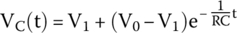
Voltage at any given time will be given by the formula
If we plug in the known values, we get
Current at any given time can be calculated by the following formula:
By plugging in the known values, we get
25.4.2 Example 2
Figure 25.4 shows a DC power supply, a resistor, a capacitor, and a two‐position switch.
Figure 25.4 RC circuit initially working.
The switch has been closed for a long time connecting points A and B. Thus, R and C have been connected across a constant voltage source, V1, for a long time. The circuit is on the steady‐state phase, C is completely charged, and there is no more current flowing.
At time t = 0s, the switch is moved from position AB to AC, disconnecting R and C from the power supply and connecting them parallel.
- What is the current flowing in the circuit before the switch is moved?
- What is the current flowing in the circuit as the switch is moved?
- What is the voltage across the capacitor 2 s after the switch is moved?
- What is the current flowing in the circuit 2 s after the switch is moved?
25.4.2.1 Current Before the Switch Is Moved
The circuit was working for a long time before the switch is moved. The capacitor was fully charged and no more current was flowing.
25.4.2.2 Current as the Switch Is Moved
The moment the switch moves from AB to AC, there is a potential difference across the resistor. This drives a current to flow. The capacitor has now a path to discharge and will do it slowly through the resistor.
The flow of current will start out big and gradually decay exponentially to 0.
The initial big current can be calculated by simple Ohm’s law:
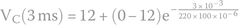
25.4.2.3 Voltage After 2 s
As soon as the switch is moved, the capacitor starts to discharge. The following formula can be used to calculate its voltage 2 s into discharge:
By plugging in the known values, we get
We can obtain the same value by using the general formula:
where V0 is equal to capacitor initial voltage, which is equal to the power supply voltage (5 V), and V∞ is 0, because at an infinite time the capacitor will be completely discharged.
Upon substituting these values on the general formula, for t = 2 s, we obtain the same value as before:
25.4.2.4 Current After 2 s
To calculate the current flowing in the circuit two seconds into discharge, we can use the following formula:
By plugging in the known values, we get
The negative sign means that current is flowing in the opposite direction during discharge, compared to the direction it flows during charge.
25.4.3 Example 3
Figure 25.5 shows a circuit with two DC power supplies, two resistors, a capacitor, and a two‐position switch.
Figure 25.5 RC circuit with two voltage sources.
In the following circuit, V1, R1, and C make the main circuit. This part of the circuit is working for a long time, C is fully charged, and there is no current flowing in that part of the circuit anymore. Voltage across the capacitor is the same as power supply voltage, V1, which is 15 V.
The secondary part of the circuit is composed of R2, V2, and a switch that is initially open, making this part of the circuit electrically isolated from other part. There is no current flowing in that part of the circuit initially.
At time t = 0 s, the switch is closed, connecting the secondary circuit to the main circuit.
We want to know the voltage across the capacitor after the switch is closed and circuit stabilizes.
25.4.3.1 After the Switch Is Closed
As the switch is closed, components R1/V1 and C are put parallel with R2/V2.
Notice that V2’s polarity is reversed compared with V1’s.
A new transient phase begins. The circuit tries to stabilize for the new values of resistance and voltages. During this new transient phase, current will flow as shown in Figure 25.6.
Figure 25.6 RC circuit tries to stabilize.
To best understand the circuit, consider the voltages of points A and B in relation to ground as seen in Figure 25.7.

Figure 25.7 RC circuit tries to stabilize.
Figure 25.7 shows, clearly, that voltages of points A and B, in relation to ground, are +15 V and −8 V, respectively.
By subtracting these two voltages, we can get the difference in potential between points A and B:
To calculate the voltage across the capacitor when the circuit stabilizes, all we must do is to calculate the voltage at point S, removing the capacitor from the circuit.
Currents across R1 and R2 are
Without the capacitor, i1 and i2 are the same current; thus we can equate them and obtain the voltage across the capacitor when the circuit stabilizes:
25.4.4 Example 4
Figure 25.8 shows a circuit with an alternating current power supply, a resistor, a capacitor, and a switch permanently closed. The circuit is working like this for a long time.

Figure 25.8 AC powered RC circuit.
V1 is a sinusoidal alternating voltage source. Its amplitude is 10 V and its frequency is 50 Hz.
This is what we want to know about the circuit:
- The circuit’s impedance and its phase angle.
- The root mean square (RMS) current flowing in the circuit.
- The circuit’s power factor.
- The apparent, the real, and the reactive power.
25.4.4.1 Circuit’s Impedance
The impedance of a resistor (ZR) is its own value of resistance (R), because resistors have no reactance.
Thus,
For a series RC circuit, the total impedance will be the resistor’s impedance added to the capacitor’s impedance, or
Capacitor’s impedance is related to its reactance by
where XC is the capacitor’s reactance and −j is the impedance’s imaginary part.
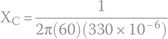
Capacitor’s reactance can be found by plugging in the known values in the following formula:
Hence, capacitor’s impedance is
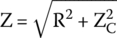
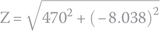
and the circuit’s total impedance is
By converting the complex impedance to phasor notation, we get the impedance’s magnitude:
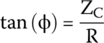
and for the phase angle,
Figure 25.9 shows the impedance triangle. Horizontal axis represents impedance’s real part (Re), in this case equal to resistance R, and the capacitor reactance XC is the imaginary part (Im). The impedance magnitude Z is the triangle’s hypotenuse. Its angle to the real axis is the phase angle ϕ.
Capacitive circuits will always have negative imaginary terms.

Figure 25.9 Impedance triangle.
25.4.4.2 RMS Current
VRMS can be calculated by using the following formula:
By plugging in the power supply maximum voltage VMAX of 10 V, we get
The magnitude of impedance, already calculated as 5.112 Ω, can be used to find the RMS current:
25.4.4.3 Power Factor and Phase Angle
The power factor of a series RC circuit powered by alternating current is equal to the resistance divided by the impedance magnitude.
By plugging in
we get
25.4.4.4 The Apparent, the Real, and the Reactive Power
The apparent, the real and the reactive powers can be calculated by the following formulas.
The real power is then calculated by plugging in the known values for the given circuit:
For the reactive power,
The negative sign represents a capacitive reactive power and is, generally, never used to represent Q. Thus, the result is shown below.
The apparent power can be calculated as
Exercises
- Consider the circuit shown in Figure 25.10, composed of a resistor and a capacitor in series with a switch and a direct voltage power supply. The switch is initially open, so the circuit is not working. The capacitor is completely discharged.
Figure 25.10 RC circuit and an open switch.
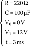
The components in the circuit are

At time t = 0 s, the switch is closed.
The following is what we want to find:
- What is the current flowing in the circuit before the switch is closed?
- What is the current flowing in the circuit after the switch is closed?
- What is the current flowing in the circuit 5 ms after the switch is closed?
- What is the voltage across capacitor (VAB) 3 ms after the switch is closed?
- Figure 25.11 shows a DC power supply, a resistor, a capacitor, and a two‐position switch.
Figure 25.11 RC circuit and a two‐pole switch.
The switch has been closed for a long time, connecting points A and B.
For that reason, the resistor and the capacitor have been connected to the power supply for a long time, and the capacitor is fully charged.
The components in the circuit are

At time t = 0 s, the switch is moved from AB to AC, putting the capacitor and the resistor in parallel.
The following is what we want to find:
- What is the current flowing in the circuit before the switch is moved?
- What is the current flowing in the circuit after the switch is moved?
- What is the current flowing in the circuit 4 ms after the switch is moved?
- What is the voltage across capacitor 5 ms after the switch is moved?
- Figure 25.12 shows a circuit with two DC power supplies, two resistors, a capacitor, and a switch.
Figure 25.12 RC circuit with two voltage sources.
V1, R1, and C make the main circuit. This part of the circuit is working for a long time like this. For that reason, the capacitor is fully charged.
The secondary circuit is composed of R2, V2, and a switch in series, and the switch is initially open.
The components in the circuit are

At time t = 0 s, the switch is closed, connecting the second circuit to the first.
The following is what we want to find:
- What is the voltage across capacitor after the circuit stabilizes?
- What is the voltage across capacitor 3 ms after the switch is closed?
- Figure 25.13 shows a circuit with an alternating current power supply, a resistor, a capacitor, and a switch in series. The switch is permanently closed. The circuit is working like this for a long time.

Figure 25.13 AC powered RC circuit.
The components in the circuit are

The following is what we want to find:
- What are the circuit’s impedance and its phase angle?
- What is the RMS current flowing in the circuit?
- What is the circuit’s power factor?
- What are the apparent, the real and the reactive power?
Solutions
What is the current flowing in the circuit before the switch is closed?
Before the switch is closed, there is no current flowing in the circuit, because the switch is open and there is no circuit continuity.
What is the current flowing in the circuit after the switch is closed?
The moment the switch is turned on, voltage across the capacitor (VC) is 0, and the capacitor will offer zero resistance to the current flow, behaving like a regular wire or short circuit, letting maximum current pass.
By Kirchhoff’s law,
We know that

Upon substituting these values on the equation, we get


By plugging in the known values

we get

What is the current flowing in the circuit 5 ms after the switch is closed?
In an RC series circuit, current at any given time can be found by the following formula:
If we plug in the known values,

we get

What is the voltage across capacitor ( V AB ) 3 ms after the switch is closed?
Voltage at any given time can be found by using the following formula with the known values we have:
- What is the current flowing in the circuit before the switch is moved?
The main part of the circuit was working for a long time before the switch is moved. The capacitor was fully charged and no more current was flowing.
What is the current flowing in the circuit after the switch is moved?
The moment the switch moves from AB to AC, the capacitor is fully charged, and this charge will produce a difference in potential across the resistor. Voltage across the capacitor is equal to V1. This drives a current to flow. The capacitor has now a path to discharge and will do it slowly through the resistor.
The flow of current will start out big and gradually decay exponentially to 0.
The initial current can be calculated by using the values we have:

and by applying the first Ohm’s law,


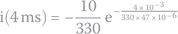
What is the current flowing in the circuit 4 ms after the switch is moved?
To calculate the current flowing in the circuit 4 ms after the switch is moved, we use the following formula:
By plugging in the known values

we get
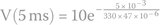
What is the voltage across capacitor 5 ms after the switch is moved?
As soon as the switch is moved, the capacitor starts to discharge. The following formula can be used to calculate its voltage 5 ms into discharge:
By plugging in the known values

we get
- What is the voltage across capacitor after the circuit stabilizes?
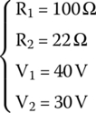
V1, R1, and C make the main circuit. This part of the circuit is working for a long time, C is fully charged, and there is no current flowing anymore on that part. Voltage across the capacitor is the same as the power supply voltage V1, which is 40 V.
As the switch is closed, components R1/V1 are put parallel with R2/V2.
A new transient phase begins, as the circuit tries to stabilize for the new values of resistance and voltages.
Voltage at point S
Points A and B have 40 V and 30 V, respectively. Resistors R1 and R2 are connected between A and B. By subtracting these voltages, we conclude that R1 and R2 are subjected to a difference in potential of 10 V.
The way these resistors are connected between A and B makes them a simple voltage divider. We can use Ohm’s law to find the voltage at point S, which is exactly the voltage across the capacitor when the circuit stabilizes.
Currents flowing across R1 and R2 are
Without capacitor, currents flowing across R1 and R2, which are
 and
and  , respectively, are the same current; thus, we can equate their equations:
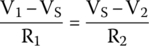
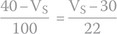
By plugging in the known values
we get the voltage at point S or, in other words the voltage across the capacitor when the circuit stabilizes (V∞):


What is the voltage across capacitor 3 ms after the switch is closed?
Voltage across the capacitor before the switch is closed is 40 V. As soon as the switch is closed, a new transient phase begins and the voltage across the capacitor slowly decays to 31.8032 V.
If we substitute both voltage sources with wires, it shows that the capacitor is in parallel with both resistors, R1 and R2.
The equivalent resistance of these resistors is
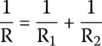

Hence, as soon as the switch is closed, the capacitor will be put in parallel with a resistance equal to 18.0327 Ω, meaning that it will discharge from 40 to 31.8032 V through this resistance.
To calculate the voltage across the capacitor after the time required, we must use the following equation:
by plugging in the known values

we get,

- What are the circuit’s impedance and its phase angle?
The impedance of a resistor (ZR) is its own value of resistance (R), because resistors have no reactance.
Thus,
For a series RC circuit, the total impedance will be the resistor’s impedance added to the capacitor’s impedance, or
Capacitor’s impedance is related to its reactance by

where XC is the capacitor’s reactance and −j is the impedance’s imaginary part.
Capacitor’s reactance can be found by plugging in the known values

in the following formula:

Hence, capacitor’s impedance is

and the circuit’s total impedance is

By converting the complex impedance to phasor notation, we get the impedance’s magnitude:
and for the phase angle,


The phase angle is very small, almost horizontal, because resistance is very big compared with reactance.
What is the RMS current flowing in the circuit?
If we extend Ohm’s law to impedances, current will be defined as
By plugging in power supply maximum voltage VMAX of 48 V, we get

We can finally calculate the RMS current by plugging in VRMS into equation

What is the circuit’s power factor?
The power factor of a series RC circuit powered by alternating current is equal to the resistance divided by the impedance magnitude, or
By plugging in the known values, we get
What are the apparent, the real, and the reactive powers?
The real power can be calculated by


The reactive power is

The apparent power is

Note
- 1 The capacitor will discharge if its voltage is higher than power supply voltage.
..................Content has been hidden....................
You can't read the all page of ebook, please click here login for view all page.