16
Source Transformations: Circuit Analysis
16.1 Introduction
In this chapter, we will use voltage and current sources and perform transformations and simplify circuits, a very powerful technique of circuit analysis.
16.2 The Technique
The technique involves converting voltage sources to current sources and vice versa.
According to the technique:
- A voltage source in series with a resistor can be converted into a current source in parallel with the same resistor and vice versa, as shown in Figure 16.1.
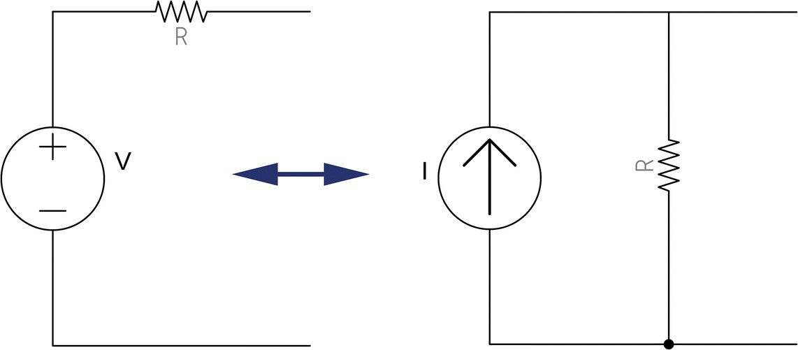
Figure 16.1 Source transformation.
- The current source arrow should always point to the voltage source's positive pole it is replacing and vice versa.
- The intensities of the voltage and current sources should be found by the following the formula.
Consider, for example, a 100 V voltage source in series with a 20 Ω resistor, as shown in Figure 16.2.
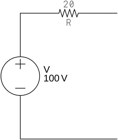
Figure 16.2 Source transformation (circuit converted).
To convert this voltage source into a current source, we must find the current source value, by using the formula
Thus,
Hence, the current source will be 5 A, and its arrow should point up, that is, the direction of the positive pole of voltage source it is replacing. The resistor is the same and should be connected in parallel. The result is shown in Figure 16.3.

Figure 16.3 Source transformation result.
16.3 Example
Suppose we want to know the value of current I1 in the circuit shown in Figure 16.4.
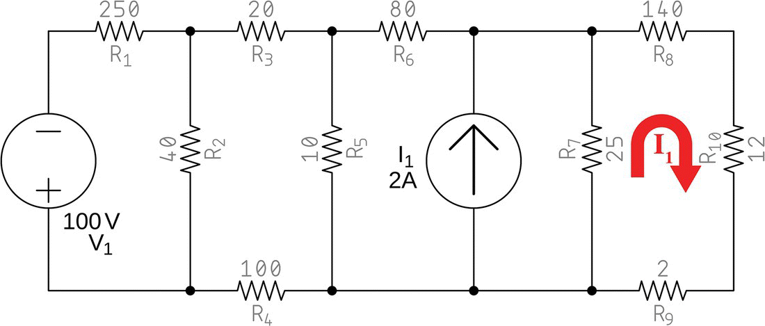
Figure 16.4 Complex circuit for simplification.
16.3.1 Solution
Let us solve this problem by using source transformations.
The circuit starts with a 100 V voltage source in series with a 250 Ω resistor (Figure 16.5).
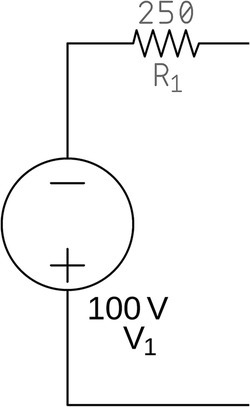
Figure 16.5 Voltage source in series with a resistor.
This can be replaced by a resistor in parallel with a current source with the following value:
The circuit can then be converted into the one shown in Figure 16.6.
The current source points down because the original voltage source had its positive pole down (see Figure 16.5).
By observing Figure 16.6, we notice two resistors in parallel, R1 equal to 250 Ω and R2 equal to 40 Ω.

Figure 16.6 First part of the circuit after first conversion.
Resistors in parallel can be replaced by an equivalent resistor with the following value:
The circuit is now like it is shown in Figure 16.7.

Figure 16.7 Equivalent circuit after second conversion.
Now we see a 0.4 A, current source in parallel with a 34.48 Ω resistor. Using the source transformation rules, we can convert this to a voltage source in series with the same resistor.
We use the formula V1 = REQ1I2 to calculate the voltage source value:
The circuit is now transformed into the one seen in Figure 16.8.
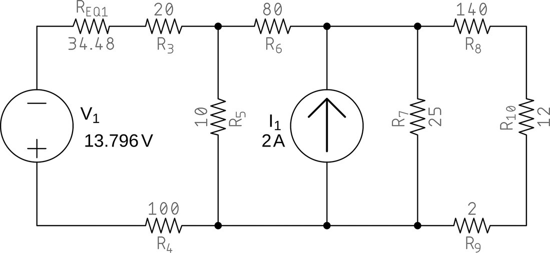
Figure 16.8 Circuit shows a voltage source in series with two resistors.
Notice that the positive pole of the voltage source points down, the same direction as the current source arrow it replaces.
Now we have resistors REQ1 and R3 in series. In terms of circuits, R4 can also be considered in series because voltage sources have zero internal resistance.
Thus, the equivalent resistor is the sum of REQ1, R3, and R4:
The circuit is now transformed into the one seen in Figure 16.9.
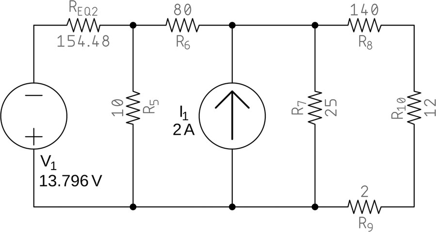
Figure 16.9 Converted circuit.
We see now, again, a voltage source (V1) in series with a resistor (REQ2), and we can convert that into a current source in parallel with the same resistor.
The current source value is found by
This transformation leads to the following circuit, shown in Figure 16.10.

Figure 16.10 Converted circuit shows a current source in parallel with two resistors.
See REQ2 and R5 in parallel? We can replace them with the equivalent resistance
The result is shown below (Figure 16.11).
The first current source (I2) in parallel with REQ3 can be replaced with a voltage source with a series resistor.
The voltage source can be found by

Figure 16.11 Converted circuit.
The result is seen in Figure 16.12.

Figure 16.12 Converted circuit.
No need to mention that REQ3 and R6 are in series and can be replaced by an equivalent resistor equal to their sum, that is, 89.39 Ω.
No need to mention also that this resistor in series with the voltage source can be replaced by a current source in parallel with the same resistor.
The current source will be
The converted circuit is shown in Figure 16.13.
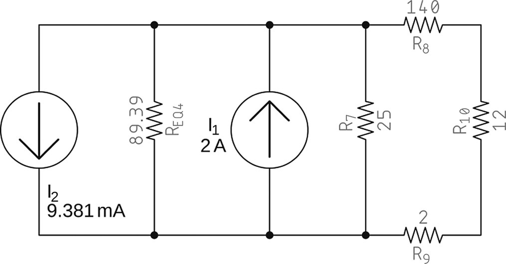
Figure 16.13 Converted circuit.
We now have four elements in parallel: two current sources, I1 and I2, and two resistors, REQ4 and R7.
Parallel resistors can be replaced by their equivalent
The current sources can be replaced by their equivalent by adding them. The second current source has a negative value, because it is pointing down.
The equivalent current source will be
The result is shown in Figure 16.14.
Notice that the final current source points up, because the sum of the two current sources was positive.
The last circuit shows another resistor in parallel with a current source, and those can be converted into a voltage source in series with the same resistor.
The voltage source will be
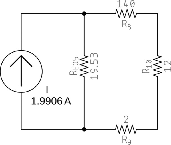
Figure 16.14 Converted circuit.
The final circuit is converted into what is shown in Figure 16.15.

Figure 16.15 Final circuit.
We have simplified the circuit enough. It is now easy to know the current circulating at this point.
By Ohm's law, we get
Exercises
- Convert the voltage source in series with the resistor shown in Figure 16.16 into a current source in parallel with a resistor.
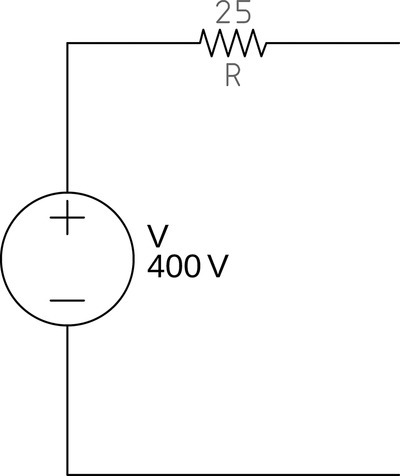
Figure 16.16 Voltage source in series with a resistor. - Convert the current source in parallel with the resistor shown in Figure 16.17 into a voltage source in series with a resistor.
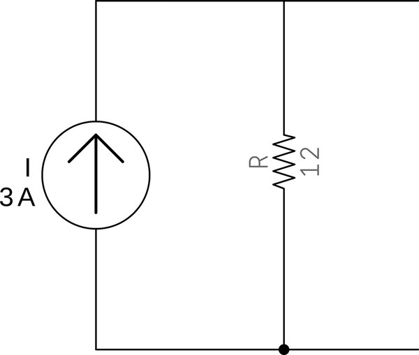
Figure 16.17 Current source in parallel with a resistor. - Figure 16.18 shows a circuit formed by several sources and resistors. Convert the circuit using the source transformation techniques to the maximum possible.
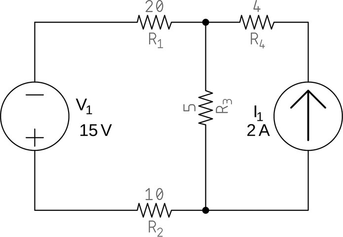
Figure 16.18 Complex circuit for source transformation (exercise).
Solutions
- If we use the source transformation rules, we can convert this circuit into a current source in parallel with the same resistor.
To find the current source value,


Thus, the 400 V voltage source in series with the 25 Ω resistor can be converted into a 16 A current source in parallel with the same resistor.
- If we use the source transformation rules, we can convert this circuit into a voltage source in series with the same resistor.
To find the voltage source value,


Thus, the 3 A current source in parallel with the 12 Ω resistor can be converted into a 36 V voltage source in series with the same resistor.
- The first thing we notice is that the voltage source is inverted. So, we are dealing with a −15 V voltage source.
Voltage sources have zero internal resistance. If we substitute this source, temporarily, with a wire, we see that R1 and R2 are in series and thus, can be substituted by the equivalent resistor, equal to 30 Ω.
The −15 V voltage source in series with a 30 Ω resistor can be replaced by a current source in parallel with the same resistor.
The current source will be


The converted circuit is seen in Figure 16.19
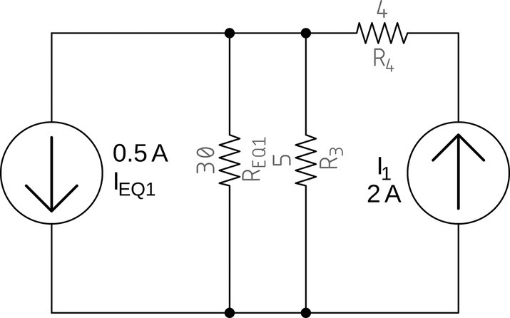
Figure 16.19 Converted circuit.
Resistors REQ1 and R3 are in parallel and can be substituted by their equivalent


The result is shown in Figure 16.20.
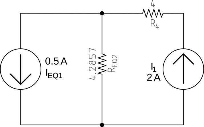
Figure 16.20 Converted circuit.
We now have the current source IEQ1 in parallel with resistor REQ2, and we can convert that into a voltage source in series with the same resistor.
The voltage source will be


The result is shown in Figure 16.21.

Figure 16.21 Converted circuit.
Figure 16.21 shows that VEQ1 is in series with REQ2 and R4. These two resistors can be replaced by their sum, as shown in Figure 16.22.
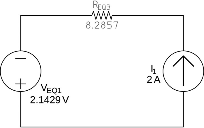
Figure 16.22 Converted circuit.
Finally, VEQ1 in series with REQ3 can be converted into a current source with the following value:


Figure 16.23 shows the result.

Figure 16.23 Converted circuit.
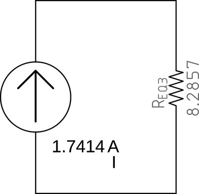
Figure 16.24 Final circuit.
We now have two current sources, with opposite signs, in parallel. We must subtract them to obtain the final circuit, shown in Figure 16.24.
