
8.7 Application Example: Compact Disc
Compact Disc™ was introduced in 1980 to provide a mass storage medium for digital audio. It has become widely used for general-purpose data storage. Compact Discs use optical storage—the data is read off the disc using a laser. The design of the CD system is a triumph of signal processing over mechanics—CD players perform a great deal of signal processing to compensate for the limitations of a cheap, inaccurate player mechanism. The DVD× and Blu-Ray™ provide higher-density optical storage. However, the basic principles governing their operation are the same as those for CD. In this section we will concentrate on the CD as an example of optical disc technology.
As shown in Figure 8.38, data is stored in pits on the bottom of a compact disc. A laser beam is reflected or not reflected by the absence or presence of a pit. The pits are very closely spaced: pits range from 0.8 to 3 microns long and 0.5 microns wide. The pits arranged in tracks with 1.6 microns between adjacent tracks.

Figure 8.38 Data stored on a compact disc.
Disks and data
Unlike magnetic disks, which arrange data in concentric circles, CD data is stored in a spiral as shown in Figure 8.39. The spiral organization makes sense if the data is to be played from beginning to end. But as we will see, the spiral complicates some aspect of CD operation.

Figure 8.39 Spiral data organization of a compact disc.
The data on a CD is divided into sectors. Each sector has an address so that the drive can determine its location on the CD. Sectors also contain several bits of control: P is 1 during music or lead-in and 0 at the start of a selection; Q contains track number, time, etc.
The compact disc mechanism is shown in Figure 8.40. A sled moves radially across the CD to be positioned at different points in the spiral data. The sled carries a laser, optics, and a photo detector. The laser illuminates the CD through the optics. The same optics capture the reflected light and pass it onto the photo detector.
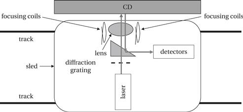
Figure 8.40 A compact disc mechanism.
CD mechanism
The optics can be focused using some simple electric coils. Laser focus adjusts for variations in the distance to the CD. As shown in Figure 8.41, an in-focus beam produces a circular spot, while an out-of-focus beam produces an elliptical spot with the beam’s major axis indicating the direction of focus. The focus can change relatively quickly depending on how the CD is seated on the spindle, so the focus needs to be continuously adjusted.

Figure 8.41 Laser focusing in a CD.
As shown in Figure 8.42, the laser pickup is divided into six regions, named A, B, C, D, E, and F. The basic four regions—A, B, C, and D—are used to determine whether the laser is focused. The focus error signal is (A + C) − (B + D). The magnitude of the signal gives the amount of focus error and the sign determines the orientation of the elliptical spot’s major axis. The sum of the four basic regions, A + B + C + D, gives the laser level to determine whether a pit is being illuminated. Two additional detectors, E and F, are used to determine when the laser has gone far off the track. Tracking error is given by E–F.
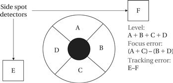
Figure 8.42 CD laser pickup regions.
The sled, focus system, and detector form a servo system. Several different systems must be controlled: laser focus and tracking must each be controlled at a sample rate of 245 kHz; the sled is controlled at 800 Hz. Control algorithms monitor the level and error signals and determine how to adjust focus, tracking, and sled signals. These control algorithms are very sophisticated. Each control may require digital filters with 30 or more coefficients. Several control modes must be programmed, such as seeking vs. playback. The development of the control algorithms usually requires several person-years of effort.
Servo control
The servo control algorithms are generally performed on a programmable DSP. Although a CD is a very low-power device which could benefit from the lower energy consumption of hardwired servo control, the complexity of the servo algorithms requires programmability. Not only are the algorithms complex, but different CD mechanisms may require different control algorithms.
The complete control system for the drive requires more than simple closed-loop control of the data. For example, when a CD is bumped, the system must reacquire the proper position on the track. Because the track is arranged in a spiral, and because the sled mechanism is inaccurate, positioning the read head is harder than in a magnetic disk. The sled must be positioned to a point before the data’s location; the system must start reading data and watch for the proper sector to appear, then start reading again.
The bits on the CD are not encoded directly. To help with tracking, the data stream must be organized to produce 0-1 transitions at some minimum interval. An eight-to-fourteen (EFM) encoding is used to ensure a minimum transition rate. For example, the eight bits of user data 00000011 are mapped to the fourteen bit code 00100100000000. The data are reconstructed from the EFM code using tables.
EFM
CDs use powerful error correction codes to compensate for inexpensive CD manufacturing processes and problems during readback. A CD contains 6.99 gigabytes of raw bits but provides only about 700 megabytes of formatted data. CDs use a form of Reed-Solomon coding; the codes are also block interleaved to reduce the effects of scratches and other bursty errors. Reed-Solomon decoding determines data and erasure bits. The time required to complete Reed-Solomon coding depends greatly on the number of erasure bits. As a result, the system may declare an entire block to be bad if decoding takes too long. Error correction is typically performed by hardwired units.
Error correction
CD players are very vulnerable to shaking. Early players could be disrupted by walking on the floor near the player. Clearly, portable or automotive players would need even stronger protection against mechanical disturbance. Memory is much cheaper today than it was when CD players were introduced. A jog memory is used to buffer data to maintain playing during a jog to the drive. The player reads ahead and puts data into the jog memory. During a jog, the audio output system reads data stored in the jog memory while the drive tries to find the proper point on the CD to continue reading.
Jog protection
Jog control memories also help reduce power consumption. The drive can read ahead, put a large block of data into the jog memory, then turn the drive off and play from jog memory. Because the drive motors consume a considerable amount of power, this strategy saves battery life. When reading compressed music from data discs, a large part of a song can be put into jog memory.
The result of error correction is the sector data. This can be easily parsed to determine the audio samples and control information. In the case of an audio disc, the samples may be directly provided to the audio output subsystem; some players use digital filters to perform part of the anti-aliasing filtering. In the case of a data disc, the sector data may be sent to the output registers.
Audio output
Figure 8.43 shows the hardware architecture of a CD player. The player includes several processors: servo processor, error correction unit, and audio unit. These processors operate in parallel to process the stream of data coming from the read mechanism.
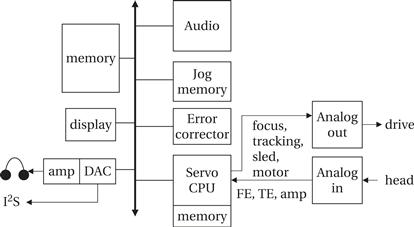
Figure 8.43 Computing platform for a CD player.
System architecture
Writable CDs provide a pilot track that allows the laser and servo to position the head. The CD system must compute Reed-Solomon codes and EFM codes to feed the DVD. Data must be provided to the write system continuously, so the host system must properly buffer data to ensure that it can be delivered on time.
CD writing
Several CD formats have been defined. Each standard is published in a separate document: the Red Book defines the CD digital audio standard: the Yellow Book defines CD-ROM; the Orange Book defines CD-RW.
CD standards