
8.4 Distributed Embedded Systems
We often use networks to build distributed embedded systems out of multiple processors. The network delays in a distributed system are generally larger than those in a tightly-coupled multiprocessor, leading to differences in how we design software. These systems can be modeled as message-passing systems. The nodes typically interact in a loosely coupled way with many of the messages specifying events. We will start by introducing the standard hierarchy for network processing. We will then look at the CAN bus and its use in cars. We will also look at I2C, which is widely used in low-cost distributed embedded systems, and Ethernet, which is used in many industrial systems. We will close with a brief look at the Internet Protocol, which is increasingly used to build real-time embedded systems.
8.4.1 Network Abstractions
Networks are complex systems. Ideally, they provide high-level services while hiding many of the details of data transmission from the other components in the system. In order to help understand (and design) networks, the International Standards Organization (ISO) has developed a seven-layer model for networks known as Open Systems Interconnection (OSI) models [Sta97A]. Understanding the OSI layers will help us to understand the details of real networks.
The seven layers of the OSI model, shown in Figure 8.4, are intended to cover a broad spectrum of networks and their uses. Some networks may not need the services of one or more layers because the higher layers may be totally missing or an intermediate layer may not be necessary. However, any data network should fit into the OSI model. The OSI model includes seven levels of abstraction:
• Physical: The physical layer defines the basic properties of the interface between systems, including the physical connections (plugs and wires), electrical properties, basic functions of the electrical and physical components, and the basic procedures for exchanging bits.
• Data link: The primary purpose of this layer is error detection and control across a single link. However, if the network requires multiple hops over several data links, the data link layer does not define the mechanism for data integrity between hops, but only within a single hop.
• Network: This layer defines the basic end-to-end data transmission service. The network layer is particularly important in multihop networks.
• Transport: The transport layer defines connection-oriented services that ensure that data are delivered in the proper order and without errors across multiple links. This layer may also try to optimize network resource utilization.
• Session: A session provides mechanisms for controlling the interaction of end-user services across a network, such as data grouping and checkpointing.
• Presentation: This layer defines data exchange formats and provides transformation utilities to application programs.
• Application: The application layer provides the application interface between the network and end-user programs.

Figure 8.4 The OSI model layers
Although it may seem that embedded systems would be too simple to require use of the OSI model, the model is in fact quite useful. Even relatively simple embedded networks provide physical, data link, and network services. An increasing number of embedded systems provide Internet service that requires implementing the full range of functions in the OSI model.
8.4.2 CAN Bus
The CAN bus[Bos07] was designed for automotive electronics and was first used in production cars in 1991. It uses bit-serial transmission. CAN can run at rates of 1 Mb/second over a twisted pair connection of 40 meters. An optical link can also be used. The bus protocol supports multiple masters on the bus.
Physical layer
As shown in Figure 8.5, each node in the CAN bus has its own electrical drivers and receivers that connect the node to the bus in wired-AND fashion. In CAN terminology, a logical 1 on the bus is called recessive and a logical 0 is dominant. The driving circuits on the bus cause the bus to be pulled down to 0 if any node on the bus pulls the bus down (making 0 dominant over 1). When all nodes are transmitting 1s, the bus is said to be in the recessive state; when a node transmits a 0, the bus is in the dominant state. Data are sent on the network in packets known as data frames.
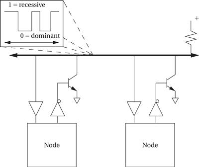
Figure 8.5 Physical and electrical organization of a CAN bus.
CAN is a synchronous bus—all transmitters must send at the same time for bus arbitration to work. Nodes synchronize themselves to the bus by listening to the bit transitions on the bus. The first bit of a data frame provides the first synchronization opportunity in a frame. The nodes must also continue to synchronize themselves against later transitions in each frame.
Data frame
The format of a CAN data frame is shown in Figure 8.6. A data frame starts with a 1 and ends with a string of seven zeroes. (There are at least three bit fields between data frames.) The first field in the packet contains the packet’s destination address and is known as the arbitration field. The destination identifier is 11 bits long. The trailing remote transmission request (RTR) bit is set to 0 if the data frame is used to request data from the device specified by the identifier. When RTR = 1, the packet is used to write data to the destination identifier. The control field provides an identifier extension and a 4-bit length for the data field with a 1 in between. The data field is from 0 to 64 bytes, depending on the value given in the control field. A cyclic redundancy check (CRC) is sent after the data field for error detection. The acknowledge field is used to let the identifier signal whether the frame was correctly received: The sender puts a recessive bit (1) in the ACK slot of the acknowledge field; if the receiver detected an error, it forces the value to a dominant (0) value. If the sender sees a 0 on the bus in the ACK slot, it knows that it must retransmit. The ACK slot is followed by a single bit delimiter followed by the end-of-frame field.
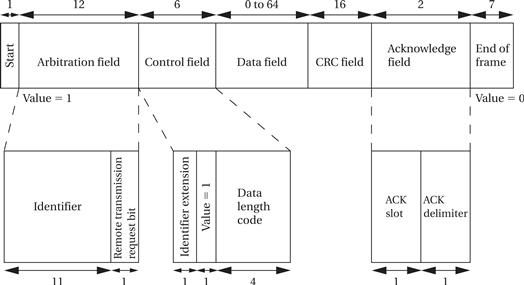
Figure 8.6 The CAN data frame format.
Arbitration
Control of the CAN bus is arbitrated using a technique known as Carrier Sense Multiple Access with Arbitration on Message Priority (CSMA/AMP). This method is similar to the I2C bus’s arbitration method; like I2C, CAN encourages a data-push programming style. Network nodes transmit synchronously, so they all start sending their identifier fields at the same time. When a node hears a dominant bit in the identifier when it tries to send a recessive bit, it stops transmitting. By the end of the arbitration field, only one transmitter will be left. The identifier field acts as a priority identifier, with the all-0 identifier having the highest priority.
Remote frames
A remote frame is used to request data from another node. The requestor sets the RTR bit to 0 to specify a remote frame; it also specifies zero data bits. The node specified in the identifier field will respond with a data frame that has the requested value. Note that there is no way to send parameters in a remote frame—for example, you cannot use an identifier to specify a device and provide a parameter to say which data value you want from that device. Instead, each possible data request must have its own identifier.
Error handling
An error frame can be generated by any node that detects an error on the bus. Upon detecting an error, a node interrupts the current transmission with an error frame, which consists of an error flag field followed by an error delimiter field of 8 recessive bits. The error delimiter field allows the bus to return to the quiescent state so that data frame transmission can resume. The bus also supports an overload frame, which is a special error frame sent during the interframe quiescent period. An overload frame signals that a node is overloaded and will not be able to handle the next message. The node can delay the transmission of the next frame with up to two overload frames in a row, hopefully giving it enough time to recover from its overload. The CRC field can be used to check a message’s data field for correctness.
If a transmitting node does not receive an acknowledgment for a data frame, it should retransmit the data frame until the data is acknowledged. This action corresponds to the data link layer in the OSI model.
Figure 8.7 shows the basic architecture of a typical CAN controller. The controller implements the physical and data link layers; because CAN is a bus, it does not need network layer services to establish end-to-end connections. The protocol control block is responsible for determining when to send messages, when a message must be resent due to arbitration losses, and when a message should be received.
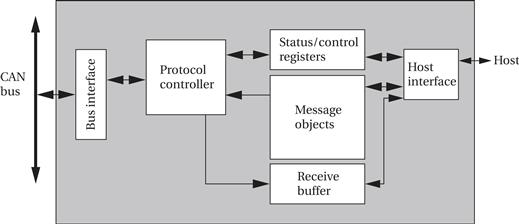
Figure 8.7 Architecture of a CAN controller.
Other automotive networks
The FlexRay network has been designed as the next generation of system buses for cars. FlexRay provides high data rates—up to 10 Mbits/sec—with deterministic communication. It is also designed to be fault-tolerant.
The Local Interconnect Network (LIN) bus [Bos07] was created to connect components in a small area, such as a single door. The physical medium is a single wire that provides data rates of up to 20 kbits/sec for up to 16 bus subscribers. All transactions are initiated by the master and responded to by a frame. The software for the network is often generated from a LIN description file that describes the network subscribers, the signals to be generated, and the frames.
Several buses have come into use for passenger entertainment. Bluetooth is becoming the standard mechanism for cars to interact with consumer electronics devices such as audio players or phones. The Media Oriented Systems Transport (MOST) bus [Bos07] was designed for entertainment and multimedia information. The basic MOST bus runs at 24.8 Mbits/sec and is known as MOST 25, and 50 and 150 Mbits/sec versions have been developed. MOST can support up to 64 devices. The network is organized as a ring.
Data transmission is divided into channels. A control channel transfers control and system management data. Synchronous channels are used to transmit multimedia data; MOST 25 provides up to 15 audio channels. An asynchronous channel provides high data rates but without the quality-of-service guarantees of the synchronous channels.
8.4.3 Distributed Computing in Cars and Airplanes
Cars provide an ideal opportunity for message passing style multiprocessing. A car is controlled by a network of processors that each has its own responsibility but must communicate with other processors to make sure that the different subsystems act together.
Car subsystems
Figure 8.8 shows a car network and three of the major subsystems in the car: the engine, the transmission, and the anti-lock braking system (ABS). Each of these is a mechanical system that is controlled by a processor. First consider the roles of the mechanical systems, all of which are mechanically coupled together:
• The engine provides power to drive the wheels.
• The transmission mechanically transforms the engine’s rotational energy into a form most useful by the wheels.
• The ABS system controls how the brakes are applied to each of the four wheels. ABS can separately control the brake on each wheel.

Figure 8.8 Major elements of an automobile network.
Now consider the roles of the associated processors:
• The engine controller accepts commands from the driver via the gas pedal. It also takes several measurements. Based on the commands and measurements, it determines the spark and fuel timing on every engine cycle.
• The transmission controller determines when to change gears.
• The ABS system takes braking commands from the driver via the brake pedal. It also takes measurements from the wheels about their rotating speed. It turns the brakes on each wheel on and off to maintain traction on each wheel.
Car subsystem interactions
These subsystems need to communicate with each other in order to do their jobs:
• The engine controller may change the spark timing during gear shifting to reduce shocks during shifting.
• The transmission controller must receive the throttle position from the engine controller to help it determine the proper shifting pattern for the transmission.
• The ABS system tells the transmission when brakes are being applied in case the gear needs to be shifted.
None of these tasks need to be performed at the highest rates in the system, which are the rates for spark timing. A relatively small amount of information can be exchanged in order to achieve the desired effect. This information can be regarded as describing events, which is a good model for message-passing communication.
The next example introduces an MPSoC designed as a gateway processor for automotive networks.
Example 8.2 Freescale MPC5676R
The MPC5676R [Fre11B] is a dual-processor platform for powertrain systems.
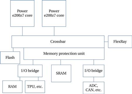
The two main processors are members of the Power Architecture™ Book E architecture and user-mode compatible with PowerPC. They provide short vector instructions for use in signal processing. Each processor has its own 16-K data and instruction caches. The time processing unit can be used to generate and read waveforms. Interfaces to the CAN, LIN, and FlexRay networks are supported.
Avionics
Aircraft electronics are known as avionics. The most fundamental difference between avionics and automotive electronics is certification. Anything that is permanently attached to the aircraft must be certified. The certification process for production aircraft is two-fold: first, the design is certified in a process known as type certification; then, the manufacture of each aircraft is certified during production.
The certification process is a prime reason why avionics architectures are more conservative than automotive electronics systems. The traditional architecture [Hel04] for an avionics system has a separate unit for each function: artificial horizon, engine control, flight surfaces, etc. These units are known as line replaceable units (LRUs) and are designed to be easily plugged and unplugged into the aircraft during maintenance.
A more sophisticated system is bus-based. The Boeing 777 avionics [Mor07], for example, is built from a series of racks. Each rack is a set of core processor modules (CPMs), I/O modules, and power supplies. The CPMs may implement one or more functions. A bus known as SAFEbus connects the modules. Cabinets are connected together using serial bus known as ARINC 629.
A more distributed approach to avionics is the federated network. In this architecture, a function or several functions have their own network. The networks share data as necessary for the interaction of these functions. A federated architecture is designed so that a failure in one network will not interfere with the operation of the other networks.
The Genesis Platform [Wal07] is a next-generation architecture for avionics and safety-critical systems; it is used on the Boeing 787 Dreamliner. Unlike federated architectures, it does not require a one-to-one correspondence between application groups and network units. In contrast, Genesis defines a virtual system for the avionics applications that are then mapped onto a physical network that may have a different topology.
8.4.4 I2C Bus
The I2C bus[Phi92] is a well-known bus commonly used to link microcontrollers into systems. It has even been used for the command interface in an MPEG-2 video chip [van97]; while a separate bus was used for high-speed video data, setup information was transmitted to the on-chip controller through an I2C bus interface.
Physical layer
I2C is designed to be low cost, easy to implement, and of moderate speed (up to 100 kilobits per second for the standard bus and up to 400 kbits/sec for the extended bus). As a result, it uses only two lines: the serial data line (SDL) for data and the serial clock line (SCL), which indicates when valid data are on the data line. Figure 8.9 shows the structure of a typical I2C bus system. Every node in the network is connected to both SCL and SDL. Some nodes may be able to act as bus masters and the bus may have more than one master. Other nodes may act as slaves that only respond to requests from masters.
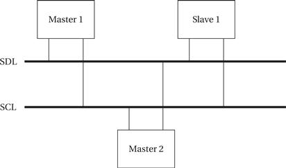
Figure 8.9 Structure of an I2C bus system.
Electrical interface
The basic electrical interface to the bus is shown in Figure 8.10. The bus does not define particular voltages to be used for high or low so that either bipolar or MOS circuits can be connected to the bus. Both bus signals use open collector/open drain circuits.1 A pull-up resistor keeps the default state of the signal high, and transistors are used in each bus device to pull down the signal when a 0 is to be transmitted. Open collector/open drain signaling allows several devices to simultaneously write the bus without causing electrical damage.

Figure 8.10 Electrical interface to the I2C bus.
The open collector/open drain circuitry allows a slave device to stretch a clock signal during a read from a slave. The master is responsible for generating the SCL clock, but the slave can stretch the low period of the clock (but not the high period) if necessary.
The I2C bus is designed as a multimaster bus—any one of several different devices may act as the master at various times. As a result, there is no global master to generate the clock signal on SCL. Instead, a master drives both SCL and SDL when it is sending data. When the bus is idle, both SCL and SDL remain high. When two devices try to drive either SCL or SDL to different values, the open collector/open drain circuitry prevents errors, but each master device must listen to the bus while transmitting to be sure that it is not interfering with another message—if the device receives a different value than it is trying to transmit, then it knows that it is interfering with another message.
Data link layer
Every I2C device has an address. The addresses of the devices are determined by the system designer, usually as part of the program for the I2C driver. The addresses must of course be chosen so that no two devices in the system have the same address. A device address is 7 bits in the standard I2C definition (the extended I2C allows 10-bit addresses). The address 0000000 is used to signal a general call or bus broadcast, which can be used to signal all devices simultaneously. The address 11110XX is reserved for the extended 10-bit addressing scheme; there are several other reserved addresses as well.
A bus transaction is comprised of a series of one-byte transmissions and an address followed by one or more data bytes. I2C encourages a data-push programming style. When a master wants to write a slave, it transmits the slave’s address followed by the data. Because a slave cannot initiate a transfer, the master must send a read request with the slave’s address and let the slave transmit the data. Therefore, an address transmission includes the 7-bit address and 1 bit for data direction: 0 for writing from the master to the slave and 1 for reading from the slave to the master. (This explains the 7-bit addresses on the bus.) The format of an address transmission is shown in Figure 8.11.

Figure 8.11 Format of an I2C address transmission.
A bus transaction is initiated by a start signal and completed with an end signal:
• A start is signaled by leaving the SCL high and sending a 1 to 0 transition on SDL.
• A stop is signaled by setting the SCL high and sending a 0 to 1 transition on SDL.
However, starts and stops must be paired. A master can write and then read (or read and then write) by sending a start after the data transmission, followed by another address transmission and then more data. The basic state transition graph for the master’s actions in a bus transaction is shown in Figure 8.12.
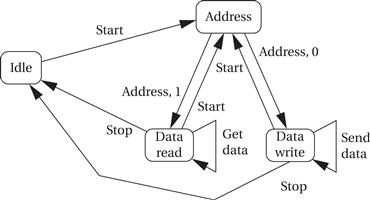
Figure 8.12 State transition graph for an I2C bus master.
The formats of some typical complete bus transactions are shown in Figure 8.13. In the first example, the master writes two bytes to the addressed slave. In the second, the master requests a read from a slave. In the third, the master writes one byte to the slave, and then sends another start to initiate a read from the slave.

Figure 8.13 Typical bus transactions on the I2C bus.
Byte format
Figure 8.14 shows how a data byte is transmitted on the bus, including start and stop events. The transmission starts when SDL is pulled low while SCL remains high. After this start condition, the clock line is pulled low to initiate the data transfer. At each bit, the clock line goes high while the data line assumes its proper value of 0 or 1. An acknowledgment is sent at the end of every 8-bit transmission, whether it is an address or data. For acknowledgment, the transmitter does not pull down the SDL, allowing the receiver to set the SDL to 0 if it properly received the byte. After acknowledgment, the SDL goes from low to high while the SCL is high, signaling the stop condition.

Figure 8.14 Transmitting a byte on the I2C bus.
Bus arbitration
The bus uses this feature to arbitrate on each message. When sending, devices listen to the bus as well. If a device is trying to send a logic 1 but hears a logic 0, it immediately stops transmitting and gives the other sender priority. (The devices should be designed so that they can stop transmitting in time to allow a valid bit to be sent.) In many cases, arbitration will be completed during the address portion of a transmission, but arbitration may continue into the data portion. If two devices are trying to send identical data to the same address, then of course they never interfere and both succeed in sending their message.
Application interface
The I2C interface on a microcontroller can be implemented with varying percentages of the functionality in software and hardware [Phi89]. As illustrated in Figure 8.15, a typical system has a 1-bit hardware interface with routines for byte-level functions. The I2C device takes care of generating the clock and data. The application code calls routines to send an address, send a data byte, and so on, which then generates the SCL and SDL, acknowledges, and so forth. One of the microcontroller’s timers is typically used to control the length of bits on the bus. Interrupts may be used to recognize bits. However, when used in master mode, polled I/O may be acceptable if no other pending tasks can be performed, because masters initiate their own transfers.

Figure 8.15 An I2C interface in a microcontroller.
8.4.5 Ethernet
Ethernet is very widely used as a local area network for general-purpose computing. Because of its ubiquity and the low cost of Ethernet interfaces, it has seen significant use as a network for embedded computing. Ethernet is particularly useful when PCs are used as platforms, making it possible to use standard components, and when the network does not have to meet rigorous real-time requirements.
The physical organization of an Ethernet is very simple, as shown in Figure 8.16. The network is a bus with a single signal path; the Ethernet standard allows for several different implementations such as twisted pair and coaxial cable.
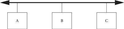
Figure 8.16 Ethernet physical organization.
Unlike the I22C or CAN bus, nodes on the Ethernet are not synchronized—they can send their bits at any time. I22C and CAN rely on the fact that a collision can be detected and quashed within a single bit time thanks to synchronization. But because Ethernet nodes are not synchronized, if two nodes decide to transmit at the same time, the message will be ruined. The Ethernet arbitration scheme is known as Carrier Sense Multiple Access with Collision Detection (CSMA/CD). The algorithm is outlined in Figure 8.17. A node that has a message waits for the bus to become silent and then starts transmitting. It simultaneously listens, and if it hears another transmission that interferes with its transmission, it stops transmitting and waits to retransmit. The waiting time is random, but weighted by an exponential function of the number of times the message has been aborted. Figure 8.18 shows the exponential backoff function both before and after it is modulated by the random wait time. Because a message may be interfered with several times before it is successfully transmitted, the exponential backoff technique helps to ensure that the network does not become overloaded at high demand factors. The random factor in the wait time minimizes the chance that two messages will repeatedly interfere with each other.

Figure 8.17 The Ethernet CSMA/CD algorithm.
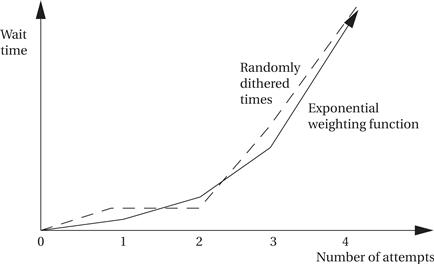
Figure 8.18 Exponential backoff times.
The maximum length of an Ethernet is determined by the nodes’ ability to detect collisions. The worst case occurs when two nodes at opposite ends of the bus are transmitting simultaneously. For the collision to be detected by both nodes, each node’s signal must be able to travel to the opposite end of the bus so that it can be heard by the other node. In practice, Ethernets can run up to several hundred meters.
Figure 8.19 shows the basic format of an Ethernet packet. It provides addresses of both the destination and the source. It also provides for a variable-length data payload.
![]()
Figure 8.19 Ethernet packet format.
The fact that it may take several attempts to successfully transmit a message and that the waiting time includes a random factor makes Ethernet performance difficult to analyze. It is possible to perform data streaming and other real-time activities on Ethernets, particularly when the total network load is kept to a reasonable level, but care must be taken in designing such systems.
Real-time operations over Ethernet
Ethernet was not designed to support real-time operations; the exponential backoff scheme cannot guarantee delivery time of any data. Because so much Ethernet hardware and software are available, many different approaches have been developed to extend Ethernet to real-time operation; some of these are compatible with the standard while others are not. As Decotignie points out [Dec05], there are three ways to reduce the variance in Ethernet’s packet delivery time: suppress collisions on the network, reduce the number of collisions, or resolve collisions deterministically. Felser [Fel05] describes several real-time Ethernet architectures.
Other industrial networks
Manufacturing systems require networked sensors and actuators. Fieldbus (http://www.fieldbus.org) is a set of standards for industrial control and instrumentation systems. The H1 standard uses a twisted-pair physical layer that runs at 31.25 Mbits/sec. It is designed for device integration and process control. The High Speed Ethernet (HSE) standard is used for backbone networks in industrial plants. It is based on the 100-Mbit/sec Ethernet standard. It can integrate devices and subsystems.
8.4.6 Internet
The Internet Protocol (IP)[Los97, Sta97A] is the fundamental protocol on the Internet. It provides connectionless, packet-based communication. Industrial automation has long been a good application area for Internet-based embedded systems. Information appliances that use the Internet are rapidly becoming another use of IP in embedded computing.
Internetworking
IP is not defined over a particular physical implementation—it is an internetworking standard. Internet packets are assumed to be carried by some other network, such as an Ethernet. In general, an Internet packet will travel over several different networks from source to destination. The IP allows data to flow seamlessly through these networks from one end user to another. The relationship between IP and individual networks is illustrated in Figure 8.20. IP works at the network layer. When node A wants to send data to node B, the application’s data pass through several layers of the protocol stack to get to the Internet Protocol. IP creates packets for routing to the destination, which are then sent to the data link and physical layers. A node that transmits data among different types of networks is known as a router. The router’s functionality must go up to the IP layer, but because it is not running applications, it does not need to go to higher levels of the OSI model. In general, a packet may go through several routers to get to its destination. At the destination, the IP layer provides data to the transport layer and ultimately the receiving application. As the data pass through several layers of the protocol stack, the IP packet data are encapsulated in packet formats appropriate to each layer.

Figure 8.20 Protocol utilization in Internet communication.
The basic format of an IP packet is shown in Figure 8.21. The header and data payload are both of variable length. The maximum total length of the header and data payload is 65,535 bytes.
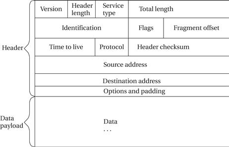
Figure 8.21 IP packet structure.
An Internet address is a number (32 bits in early versions of IP, 128 bits in IPv6). The IP address is typically written in the form xxx.xx.xx.xx. The names by which users and applications typically refer to Internet nodes, such as foo.baz.com, are translated into IP addresses via calls to a Domain Name Server (DNS), one of the higher-level services built on top of IP.
The fact that IP works at the network layer tells us that it does not guarantee that a packet is delivered to its destination. Furthermore, packets that do arrive may come out of order. This is referred to as best-effort routing. Because routes for data may change quickly with subsequent packets being routed along very different paths with different delays, real-time performance of IP can be hard to predict. When a small network is contained totally within the embedded system, performance can be evaluated through simulation or other methods because the possible inputs are limited. Because the performance of the Internet may depend on worldwide usage patterns, its real-time performance is inherently harder to predict.
The Internet also provides higher-level services built on top of IP. The Transmission Control Protocol (TCP) is one such example. It provides a connection-oriented service that ensures that data arrive in the appropriate order, and it uses an acknowledgment protocol to ensure that packets arrive. Because many higher-level services are built on top of TCP, the basic protocol is often referred to as TCP/IP.
Figure 8.22 shows the relationships between IP and higher-level Internet services. Using IP as the foundation, TCP is used to provide File Transport Protocol (FTP) for batch file transfers, Hypertext Transport Protocol (HTTP) for World Wide Web service, Simple Mail Transfer Protocol (SMTP) for email, and Telnet for virtual terminals. A separate transport protocol, User Datagram Protocol (UDP), is used as the basis for the network management services provided by the Simple Network Management Protocol (SNMP).
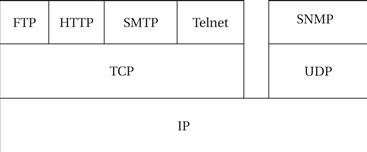
Figure 8.22 The Internet service stack.