
4.9 Design Example: Audio Player
In this example we study the design of a portable MP3 player that decompresses music files as it plays.
4.9.1 Theory of Operation and Requirements
Audio players are often called MP3 players after the popular audio data format, although a number of audio compression formats have been developed and are in regular use. The earliest portable MP3 players were based on compact disc mechanisms. Modern MP3 players use either flash memory or disk drives to store music. An MP3 player performs three basic functions: audio storage, audio decompression, and user interface.
Audio decompression
Although audio compression is computationally intensive, audio decompression is relatively lightweight. The incoming bit stream has been encoded using a Huffman-style code, which must be decoded. The audio data itself is applied to a reconstruction filter, along with a few other parameters. MP3 decoding can, for example, be executed using only 10% of an ARM7 CPU.
Audio compression is a lossy process that relies on perceptual coding. The coder eliminates certain features of the audio stream so that the result can be encoded in fewer bits. It tries to eliminate features that are not easily perceived by the human audio system. Masking is one perceptual phenomenon that is exploited by perceptual coding. One tone can be masked by another if the tones are sufficiently close in frequency. Some audio features can also be masked if they occur too close in time after another feature.
The term MP3 comes from MPEG-1, layer 3; the MP3 spec is part of the MPEG-1 standard. That standard [Bra94] defined three layers of audio compression:
• Layer 1 (MP1) uses a lossless compression of subbands and an optional, simple masking model.
• Layer 2 (MP2) uses a more advanced masking model.
• Layer 3 (MP3) performs additional processing to provide lower bit rates.
The various layers support several different input sampling rates, output bit rates, and modes (mono, stereo, etc.).
We will concentrate on Layer 1, which illustrates the basic principles of MPEG audio coding. Figure 4.39 gives a block diagram of a Layer 1 encoder. The main processing path includes the filter bank and the quantizer/encoder. The filter bank splits the signal into a set of 32 subbands that are equally spaced in the frequency domain and together cover the entire frequency range of the audio. Audio signals tend to be more correlated within a narrower band, so splitting into subbands helps the encoder reduce the bit rate. The quantizer first scales each subband so that it fits within 6 bits of dynamic range, then quantizes based upon the current scale factor for that subband. The masking model selects the scale factors. It is driven by a separate fast Fourier transform (FFT); although in principle the filter bank could be used for masking, a separate FFT provides better results. The masking model chooses the scale factors for the subbands, which can change along with the audio stream. The MPEG standard does not dictate any particular masking model. The multiplexer at the output of the encoder passes along all the required data.
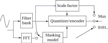
Figure 4.39 MPEG Layer 1 encoder.
MPEG data streams are divided into frames. A frame carries the basic MPEG data, error correction codes, and additional information. Figure 4.40 shows the format of an MPEG Layer 1 data frame.
![]()

Figure 4.40 MPEG Layer 1 data frame format.
Figure 4.41 MPEG Layer 1 decoder.
MPEG audio decoding is a relatively straightforward process. A block diagram of an MPEG Layer 1 decoder is shown in Figure 4.41. After disassembling the data frame, the data are unscaled and inverse quantized to produce sample streams for the subband. An inverse filter bank then reassembles the subbands into the uncompressed signal.
User interface
The user interface of an MP3 player is usually kept simple to minimize both the physical size and power consumption of the device. Many players provide only a simple display and a few buttons.
File system
The file system of the player generally must be compatible with PCs. CD/MP3 players used compact discs that had been created on PCs. Today’s players can be plugged into USB ports and treated as disk drives on the host processor.
| Name | Audio player |
| Purpose | Play audio from files. |
| Inputs | Flash memory socket, on/off, play/stop, menu up/down. |
| Outputs | Speaker |
| Functions | Display list of files in flash memory, select file to play, play file. |
| Performance | Sufficient to play audio files at required rate. |
| Manufacturing cost | Approximately $25 |
| Power | 1 AAA battery |
| Physical size and weight | Approx. 1 in x 2 in, less than 2 oz |
The requirements table for the audio player are given in Figure 4.42. Although a commercial audio player would support at least MP3, a class project could be based on a player that used a simpler compression scheme. The specification could be extended to include USB for direct management of files on the device from a host system. These requirements state that the device should accept flash memory cards on which audio files have previously been loaded.

Figure 4.42 Requirements for the audio player.
4.9.2 Specification
Figure 4.43 shows the major classes in the audio player. The FileID class is an abstraction of a file in the flash file system. The controller class provides the method that operates the player.
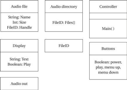
Figure 4.43 Classes in the audio player.
If file management is performed on a host device, then the basic operations to be specified are simple: file display/selection and playback.
Figure 4.44 shows a state diagram for file display/selection. This specification assumes that all files are in the root directory and that all files are playable audio.
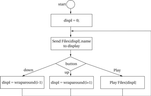
Figure 4.44 State diagram for file display and selection.
Figure 4.45 shows the state diagram for audio playback. The details of this operation depend on the format of the audio file. This state diagram refers to sending the samples to the audio system rather than explicitly sending them because playback and reading the next data frame must be overlapped to ensure continuous operation. The details of playback depend on the hardware platform selected, but will probably involve a DMA transfer.

Figure 4.45 State diagram for audio playback.
4.9.3 System Architecture
Audio processors
The Cirrus CS7410 [Cir04B] is an audio controller designed for CD/MP3 players. The audio controller includes two processors. The 32-bit RISC processor is used to perform system control and audio decoding. The 16-bit DSP is used to perform audio effects such as equalization. The memory controller can be interfaced to several different types of memory: flash memory can be used for data or code storage; DRAM can be used as a buffer to handle temporary disruptions of the CD data stream. The audio interface unit puts out audio in formats that can be used by A/D converters. General-purpose I/O pins can be used to decode buttons, run displays, etc. Cirrus provides a reference design for a CD/MP3 player [Cir04A].
As shown in Figure 4.46, the Cirrus chip uses two processors, a RISC and a DSP. Given the low computational requirements of audio decompression, a single-processor platform would also be feasible.
The software architecture of this system is relatively simple. The only major complication occurs from the requirements for DMA or other method to overlap audio playback and file access.
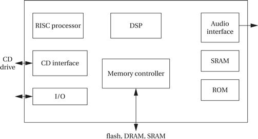
Figure 4.46 Architecture of a Cirrus audio processor for CD/MP3 players.
File systems
MP3 audio players originated a grassroots phenomenon. MP3 was designed to be used in conjunction with the MPEG-1 video compression standard. Home music collectors adopted MP3 files as a medium for storing compressed music. They passed around collections of MP3 files and playlists. These files were often shared as files written on CDs. Over time, consumer electronics manufacturers noticed the trend and made players for MP3 files. Because this approach was independently practiced by many different users, there are no standards for organizing MP3 files and playlists into directories. As a result, MP3 players must be able to navigate arbitrary user hierarchies, be able to find playlist files in any directory, etc. Manufacturers learned a lesson from this experience and defined file system organizations for other types of devices such as digital still cameras.
4.9.4 Component Design and Testing
The audio decompression object can be implemented from existing code or created as new software. In the case of an audio system that does not conform to a standard, it may be necessary to create an audio compression program to create test files.
The file system can either implement a known standard such as DOS FAT or can implement a new file system. While a nonstandard file system may be easier to implement on the device, it also requires software to create the file system.
The file system and user interface can be tested independently of the audio decompression system. The audio output system should be tested separately from the compression system. Testing of audio decompression requires sample audio files.
4.9.5 System Integration and Debugging
The most challenging part of system integration and debugging is ensuring that audio plays smoothly and without interruption. Any file access and audio output that operate concurrently should be separately tested, ideally using an easily recognizable test signal. Simple test signals such as tones will more readily show problems such as missed or delayed samples.