
6.11 Design Example: Engine Control Unit
In this section, we design a simple engine control unit (ECU). This unit controls the operation of a fuel-injected engine based on several measurements taken from the running engine.
6.11.1 Theory of Operation and Requirements
We will design a basic engine controller for a simple fuel injected engine [Toy]. As shown in Figure 6.36, the throttle is the command input. The engine measures throttle, RPM, intake air volume, and other variables. The engine controller computes injector pulse width and spark. This design doesn’t compute all the outputs required by a real engine—we only concentrate on a few essentials. We also ignore the different modes of engine operation: warm-up, idle, cruise, etc. Multi-mode control is one of the principal advantages of engine control units but we will concentrate here on a single mode to illustrate basic concepts in multi-rate control.
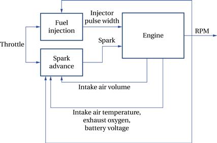
Figure 6.36 Engine block diagram.
Our requirements chart for the ECU is shown in Figure 6.37.
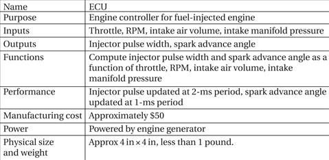
Figure 6.37 Requirements for the engine controller.
6.11.2 Specification
The engine controller must deal with processes that happen at different rates. Figure 6.38 shows the update periods for the different signals.
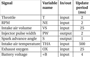
Figure 6.38 Periods for data in the engine controller.
We will use ΔNE and ΔT to represent the change in RPM and throttle position, respectively. Our controller computes two output signals, injector pulse width PW and spark advance angle S [Toy]. It first computes initial values for these variables:
![]() (Eq. 6.6)
(Eq. 6.6)
![]() (Eq. 6.7)
(Eq. 6.7)
The controller then applies corrections to these initial values:
• As the intake air temperature (THA) increases during engine warm-up, the controller reduces the injection duration.
• As the throttle opens, the controller temporarily increases the injection frequency.
• The controller adjusts duration up or down based upon readings from the exhaust oxygen sensor (OX).
• The injection duration is increased as the battery voltage (+B) drops.
6.11.3 System Architecture
Figure 6.39 shows the class diagram for the engine controller. The two major processes, pulse-width and advance-angle, compute the control parameters for the spark plugs and injectors.
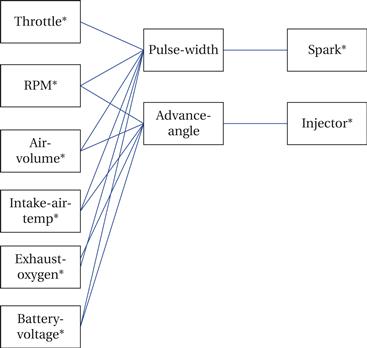
Figure 6.39 Class diagram for the engine controller.
The control parameters rely on changes in some of the input signals. We will use the physical sensor classes to compute these values. Each change must be updated at the variable’s sampling rate. The update process is simplified by performing it in a task that runs at the required update rate. Figure 6.40 shows the state diagram for throttle sensing, which saves both the current value and change in value of the throttle. We can use similar control flow to compute changes to the other variables.
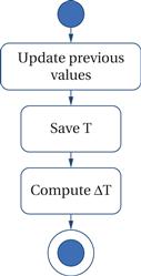
Figure 6.40 State diagram for throttle position sensing.
Figure 6.41 shows the state diagram for injector pulse width and Figure 6.42 shows the state diagram for spark advance angle. In each case, the value is computed in two stages, first an initial value followed by a correction.
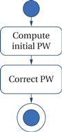
Figure 6.41 State diagram for injector pulse width.
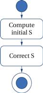
Figure 6.42 State diagram for spark advance angle.
The pulse-width and advance-angle processes do not, however, generate the waveforms to drive the spark and injector waveforms. These waveforms must be carefully timed to the engine’s current state. Each spark plug and injector must fire at exactly the right time in the engine cycle, taking into account the engine’s current speed as well as the control parameters.
Some engine controller platforms provide hardware units that generate high-rate, changing waveforms. One example is the MPC5602D [Fre11]. The main processor is a PowerPC processor. The enhanced modular IO subsystem (eMIOS) provides 28 input and output channels controlled by timers. Each channel can perform a variety of functions. The output pulse width and frequency modulation buffered mode (OPWFMB) will automatically generate a waveform whose period and duty cycle can be varied by writing registers in the eMIOS. The details of the waveform timing are then handled by the output channel hardware.
Because these objects must be updated at different rates, their execution will be controlled by an RTOS. Depending on the RTOS latency, we can separate the I/O functions into interrupt service handlers and threads.
6.11.4 Component Design and Testing
The various tasks must be coded to satisfy the requirements of RTOS processes. Variables that are maintained across task execution, such as the change-of-state variables, must be allocated and saved in appropriate memory locations. The RTOS initialization phase is used to set up the task periods.
Because some of the output variables depend on changes in state, these tasks should be tested with multiple input variable sequences to ensure that both the basic and adjustment calculations are performed correctly.
The Society of Automotive Engineers (SAE) has several standards for automotive software: J2632 for coding practices for C code, J2516 for software development lifecycle, J2640 for software design requirements, J2734 for software verification and validation.
6.11.5 System Integration and Testing
Engines generate huge amounts of electrical noise that can cripple digital electronics. They also operate over very wide temperature ranges: hot during engine operation, potentially very cold before the engine is started. Any testing performed on an actual engine must be conducted using an engine controller that has been designed to withstand the harsh environment of the engine compartment.