
4.7 Platform-Level Performance Analysis
Bus-based systems add another layer of complication to performance analysis. Platform-level performance involves much more than the CPU. We often focus on the CPU because it processes instructions, but any part of the system can affect total system performance. More precisely, the CPU provides an upper bound on performance, but any other part of the system can slow down the CPU. Merely counting instruction execution times is not enough.
Consider the simple system of Figure 4.28. We want to move data from memory to the CPU to process it. To get the data from memory to the CPU we must:
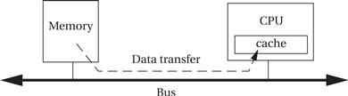
Figure 4.28 Platform-level data flows and performance.
The time required to transfer from the cache to the CPU is included in the instruction execution time, but the other two times are not.
Bandwidth as performance
The most basic measure of performance we are interested in is bandwidth—the rate at which we can move data. Ultimately, if we are interested in real-time performance, we are interested in real-time performance measured in seconds. But often the simplest way to measure performance is in units of clock cycles. However, different parts of the system will run at different clock rates. We have to make sure that we apply the right clock rate to each part of the performance estimate when we convert from clock cycles to seconds.
Bus bandwidth
Bandwidth questions often come up when we are transferring large blocks of data. For simplicity, let’s start by considering the bandwidth provided by only one system component, the bus. Consider an image of 320 # 240 pixels with each pixel composed of 3 bytes of data. This gives a grand total of 230,400 bytes of data. If these images are video frames, we want to check if we can push one frame through the system within the 1/30 sec that we have to process a frame before the next one arrives.
Let us assume that we can transfer one byte of data every microsecond, which implies a bus speed of 1 MHz. In this case, we would require 230,400 μs = 0.23 sec to transfer one frame. That is more than the 0.033 sec allotted to the data transfer. We would have to increase the transfer rate by 7# to satisfy our performance requirement.
We can increase bandwidth in two ways: we can increase the clock rate of the bus or we can increase the amount of data transferred per clock cycle. For example, if we increased the bus to carry four bytes or 32 bits per transfer, we would reduce the transfer time to 0.058 sec. If we could also increase the bus clock rate to 2 MHz, then we would reduce the transfer time to 0.029 sec, which is within our time budget for the transfer.
Bus bandwidth characteristics
How do we know how long it takes to transfer one unit of data? To determine that, we have to look at the data sheet for the bus. A bus transfer generally takes more than one clock cycle. Burst transfers, which move blocks of data to contiguous locations, may be more efficient per byte. We also need to know the width of the bus—how many bytes per transfer. Finally, we need to know the bus clock period, which in general will be different from the CPU clock period.
Bus bandwidth formulas
Let’s call the bus clock period P and the bus width W. We will put W in units of bytes but we could use other measures of width as well. We want to write formulas for the time required to transfer N bytes of data. We will write our basic formulas in units of bus cycles T, then convert those bus cycle counts to real time t using the bus clock period P:
![]() (Eq. 4.1)
(Eq. 4.1)
As shown in Figure 4.29, a basic bus transfer transfers a W-wide set of bytes. The data transfer itself takes D clock cycles. (Ideally, D = 1, but a memory that introduces wait states is one example of a transfer that could require D > 1 cycles.) Addresses, handshaking, and other activities constitute overhead that may occur before (O1 ) or after (O2 ) the data. For simplicity, we will lump the overhead into O = O1 + O2 . This gives a total transfer time in clock cycles of:
![]() (Eq. 4.2)
(Eq. 4.2)

Figure 4.29 Times and data volumes in a basic bus transfer.
As shown in Figure 4.30, a burst transaction performs B transfers of W bytes each. Each of those transfers will require D clock cycles. The bus also introduces O cycles of overhead per burst. This gives
![]() (Eq. 4.3)
(Eq. 4.3)

Figure 4.30 Times and data volumes in a burst bus transfer.
Component bandwidth
Bandwidth questions also come up in situations that we don’t normally think of as communications. Transferring data into and out of components also raises questions of bandwidth. The simplest illustration of this problem is memory.
The width of a memory determines the number of bits we can read from the memory in one cycle. That is a form of data bandwidth. We can change the types of memory components we use to change the memory bandwidth; we may also be able to change the format of our data to accommodate the memory components.
Memory aspect ratio
A single memory chip is not solely specified by the number of bits it can hold. As shown in Figure 4.31, memories of the same size can have different aspect ratios. For example, a 64-Mbit memory that is one bit wide will present 64 million addresses of one-bit data. The same size memory in a 4-bit-wide format will have 16 distinct addresses and an 8-bit-wide memory will have 8 million distinct addresses.
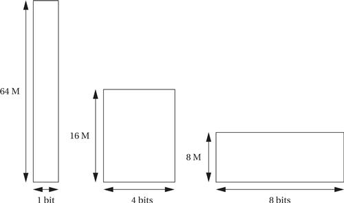
Figure 4.31 Memory aspect ratios.
Memory chips do not come in extremely wide aspect ratios but we can build wider memories by using several memories in parallel. By organizing memory chips into the proper aspect ratio for our application, we can build a memory system with the total amount of storage that we want and that presents the data width that we want.
The memory system width may also be determined by the memory modules we use. Rather than buy memory chips individually, we may buy memory as SIMMs or DIMMs. These memories are wide but generally only come in fairly standard widths.
Which aspect ratio is preferable for the overall memory system depends in part on the format of the data that we want to store in the memory and the speed with which it must be accessed, giving rise to bandwidth analysis.
Memory access times and bandwidth
We also have to consider the time required to read or write a memory. Once again, we refer to the component data sheets to find these values. Access times depend quite a bit on the type of memory chip used. Page modes operate similarly to burst modes in buses. If the memory is not synchronous, we can still refer the times between events back to the bus clock cycle to determine the number of clock cycles required for an access.
The basic form of the equation for memory transfer time is that of Eq. 4.3. where O is determined by the page mode overhead and D is the time between successive transfers.
However, the situation is slightly more complex if the data types don’t fit naturally into the width of the memory. Let’s say that we want to store color video pixels in our memory. A standard pixel is three 8-bit color values (red, green, blue, for example). A 24-bit-wide memory would allow us to read or write an entire pixel value in one access. An 8-bit-wide memory, in contrast, would require three accesses for the pixel. If we have a 32-bit-wide memory, we have two main choices: we could waste one byte of each transfer or use that byte to store unrelated data, or we could pack the pixels. In the latter case, the first read would get all of the first pixel and one byte of the second pixel; the second transfer would get the last two bytes of the second pixel and the first two bytes of the third pixel; and so forth. The total number of accesses required to read E data elements of w bits each out of a memory of width W is:
![]() (Eq. 4.4)
(Eq. 4.4)
The next example applies our bandwidth models to a simple design problem.
Example 4.3 Performance Bottlenecks in a Bus-Based System
Consider a simple bus-based system:

We want to transfer data between the CPU and the memory over the bus. We need to be able to read a 320 # 240 video frame into the CPU at the rate of 30 frames/sec, for a total of 612,000 bytes/sec. Which will be the bottleneck and limit system performance: the bus or the memory?
Let’s assume that the bus has a 1-MHz clock rate (period of 10−6 sec) and is two bytes wide, with D = 1 and O = 3. This gives a total transfer time of
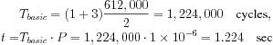
Because the total time to transfer one second’s worth of frames is more than one second, the bus is not fast enough for our application.
The memory provides a burst mode with B = 4 but is only 4 bits wide, giving W = 0.5. For this memory, D = 1 and O = 4. The clock period for this memory is 10−7 sec. Then

The memory requires less than one second to transfer the 30 frames that must be transmitted in one second, so it is fast enough.
One way to explore design trade-offs is to build a spreadsheet:

If we insert the formulas for bandwidth into the spreadsheet, we can change values like bus width and clock rate and instantly see their effects on available bandwidth.