
6.10 Design Example: Telephone Answering Machine
In this section we design a digital telephone answering machine. The system will store messages in digital form rather than on an analog tape. To make life more interesting, we use a simple algorithm to compress the voice data so that we can make more efficient use of the limited amount of available memory.
6.10.1 Theory of Operation and Requirements
In addition to studying the compression algorithm, we also need to learn a little about the operation of telephone systems.
The compression scheme we will use is known as adaptive differential pulse code modulation (ADPCM). Despite the long name, the technique is relatively simple but can yield 2× compression ratios on voice data.
The ADPCM coding scheme is illustrated in Figure 6.27. Unlike traditional sampling, in which each sample shows the magnitude of the signal at a particular time, ADPCM encodes changes in the signal. The samples are expressed in a coding alphabet, whose values are in a relatively small range that spans both negative and positive values. In this case, the value range is {−3,−2,−1,1,2,3}. Each sample is used to predict the value of the signal at the current instant from the previous value. At each point in time, the sample is chosen such that the error between the predicted value and the actual signal value is minimized.
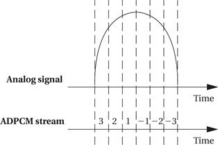
Figure 6.27 The ADPCM coding scheme.
An ADPCM compression system, including an encoder and decoder, is shown in Figure 6.28. The encoder is more complex, but both the encoder and decoder use an integrator to reconstruct the waveform from the samples. The integrator simply computes a running sum of the history of the samples; because the samples are differential, integration reconstructs the original signal. The encoder compares the incoming waveform to the predicted waveform (the waveform that will be generated in the decoder). The quantizer encodes this difference as the best predictor of the next waveform value. The inverse quantizer allows us to map bit-level symbols onto real numerical values; for example, the eight possible codes in a 3-bit code can be mapped onto floating-point numbers. The decoder simply uses an inverse quantizer and integrator to turn the differential samples into the waveform.
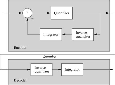
Figure 6.28 An ADPCM compression system.
The answering machine will ultimately be connected to a telephone subscriber line (although for testing purposes we will construct a simulated line). At the other end of the subscriber line is the central office. All information is carried on the phone line in analog form over a pair of wires. In addition to analog/digital and digital/analog converters to send and receive voice data, we need to sense two other characteristics of the line.
• Ringing: The central office sends a ringing signal to the telephone when a call is waiting. The ringing signal is in fact a 90 V RMS sinusoid, but we can use analog circuitry to produce 0 for no ringing and 1 for ringing.
• Off-hook: The telephone industry term for answering a call is going off-hook; the technical term for hanging up is going on-hook. (This creates some initial confusion because off-hook means the telephone is active and on-hook means it is not in use, but the terminology starts to make sense after a few uses.) Our interface will send a digital signal to take the phone line off-hook, which will cause analog circuitry to make the necessary connection so that voice data can be sent and received during the call.
| Name | Digital telephone answering machine |
| Purpose | Telephone answering machine with digital memory, using speech compression. |
| Inputs | Telephone: voice samples, ring indicator. User interface: microphone, play messages button, record OGM button. |
| Outputs | Telephone: voice samples, on-hook/off-hook command. User interface: speaker, # messages indicator, message light. |
| Functions | Default mode: When machine receives ring indicator, it signals off-hook, plays the OGM, and then records the incoming message. Maximum recording length for incoming message is 30 seconds, at which time the machine hangs up. If the machine runs out of memory, the OGM is played and the machine then hangs up without recording. Playback mode: When the play button is depressed, the machine plays all messages. If the play button is depressed again within five seconds, the messages are played again. Messages are erased after playback. OGM editing mode: When the user hits the record OGM button, the machine records an outgoing message of up to 10 seconds. When the user holds down the record OGM button and hits the play button, the OGM is played back. |
| Performance | Should be able to record about 30 minutes of total voice, including incoming and outgoing messages. Voice data are sampled at the standard telephone rate of 8 kHz. |
| Manufacturing cost | Consumer product range: approximately $50. |
| Power | Powered by AC through a standard power supply. |
| Physical size and weight | Comparable in size and weight to a desk telephone. |
We can now write the requirements for the answering machine. We will assume that the interface is not to the actual phone line but to some circuitry that provides voice samples, off-hook commands, and so on. Such circuitry will let us test our system with a telephone line simulator and then build the analog circuitry necessary to connect to a real phone line. We’ll use the term outgoing message (OGM) to refer to the message recorded by the owner of the machine and played at the start of every phone call.
We have made a few arbitrary decisions about the user interface in these requirements. The amount of voice data that can be saved by the machine should in fact be determined by two factors: the price per unit of DRAM at the time at which the device goes into manufacturing (because the cost will almost certainly drop from the start of design to manufacture) and the projected retail price at which the machine must sell. The protocol when the memory is full is also arbitrary—it would make at least as much sense to throw out old messages and replace them with new ones, and ideally the user could select which protocol to use. Extra features such as an indicator showing the number of messages or a save messages feature would also be nice to have in a real consumer product.
6.10.2 Specification
Figure 6.29 shows the class diagram for the answering machine. In addition to the classes that perform the major functions, we also use classes to describe the incoming and outgoing messages. As seen below, these classes are related.

Figure 6.29 Class diagram for the answering machine.
The definitions of the physical interface classes are shown in Figure 6.30. The buttons and lights simply provide attributes for their input and output values. The phone line, microphone, and speaker are given behaviors that let us sample their current values.
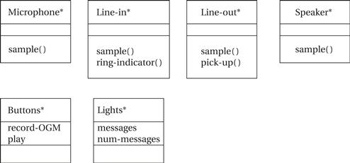
Figure 6.30 Physical class interfaces for the answering machine.
The message classes are defined in Figure 6.31. Because incoming and outgoing message types share many characteristics, we derive both from a more fundamental message type.

Figure 6.31 The message classes for the answering machine.
The major operational classes—Controls, Record, and Playback—are defined in Figure 6.32. The Controls class provides an operate() behavior that oversees the user-level operations. The Record and Playback classes provide behaviors that handle writing and reading sample sequences.

Figure 6.32 Operational classes for the answering machine.
The state diagram for the Controls activate behavior is shown in Figure 6.33. Most of the user activities are relatively straightforward. The most complex is answering an incoming call. As with the software modem of Section 5.11, we want to be sure that a single depression of a button causes the required action to be taken exactly once; this requires edge detection on the button signal.

Figure 6.33 State diagram for the Controls activate behavior.
State diagrams for record-msg and playback-msg are shown in Figure 6.34. We have parameterized the specification for record-msg so that it can be used either from the phone line or from the microphone. This requires parameterizing the source itself and the termination condition.

Figure 6.34 State diagrams for the record-msg and playback-msg behaviors.
6.10.3 System Architecture
The machine consists of two major subsystems from the user’s point of view: the user interface and the telephone interface. The user and telephone interfaces both appear internally as I/O devices on the CPU bus with the main memory serving as the storage for the messages.
The software splits into the following seven major pieces:
• The front panel module handles the buttons and lights.
• The speaker module handles sending data to the user’s speaker.
• The telephone line module handles off-hook detection and on-hook commands.
• The telephone input and output modules handle receiving samples from and sending samples to the telephone line.
• The compression module compresses data and stores it in memory.
• The decompression module uncompresses data and sends it to the speaker module.
We can determine the execution model for these modules based on the rates at which they must work and the ways in which they communicate.
• The front panel and telephone line modules must regularly test the buttons and phone line, but this can be done at a fairly low rate. As seen below, they can therefore run as polled processes in the software’s main loop.
while (TRUE) {
check_phone_line();
run_front_panel();
}
• The speaker and phone input and output modules must run at higher, regular rates and are natural candidates for interrupt processing. These modules don’t run all the time and so can be disabled by the front panel and telephone line modules when they are not needed.
• The compression and decompression modules run at the same rate as the speaker and telephone I/O modules, but they are not directly connected to devices. We will therefore call them as subroutines to the interrupt modules.
One subtlety is that we must construct a very simple file system for messages, because we have a variable number of messages of variable lengths. Because messages vary in length, we must record the length of each one. In this simple specification, because we always play back the messages in the order in which they were recorded, we don’t have to keep a full-fledged directory. If we allowed users to selectively delete messages and save others, we would have to build some sort of directory structure for the messages.
The hardware platform is straightforward and illustrated in Figure 6.35. The speaker and telephone I/O devices appear as standard A/D and D/A converters. The telephone line appears as a one-bit input device (ring detect) and a one-bit output device (off-hook/on-hook). The compressed data are kept in main memory.

Figure 6.35 Hardware platform for the answering machine.
6.10.4 Component Design and Testing
Performance analysis is important in this case because we want to ensure that we don’t spend so much time compressing that we miss voice samples. In a real consumer product, we would carefully design the code so that we could use the slowest, cheapest possible CPU that would still perform the required processing in the available time between samples. In this case, we will choose the microprocessor in advance for simplicity and simply ensure that all the deadlines are met.
An important class of problems that should be adequately tested is memory overflow. The system can run out of memory at any time, not just between messages. The modules should be tested to ensure that they do reasonable things when all the available memory is used up.
6.10.5 System Integration and Testing
We can test partial integrations of the software on our host platform. Final testing with real voice data must wait until the application is moved to the target platform.
Testing your system by connecting it directly to the phone line is not a very good idea. In the United States, the Federal Communications Commission regulates equipment connected to phone lines. Beyond legal problems, a bad circuit can damage the phone line and incur the wrath of your service provider. The required analog circuitry also requires some amount of tuning, and you need a second telephone line to generate phone calls for tests. You can build a telephone line simulator to test the hardware independently of a real telephone line. The phone line simulator consists of A/D and D/A converters plus a speaker and microphone for voice data, an LED for off-hook/on-hook indication, and a button for ring generation. The telephone line interface can easily be adapted to connect to these components, and for purposes of testing the answering machine the simulator behaves identically to the real phone line.