
3.2 Programming Input and Output
The basic techniques for I/O programming can be understood relatively independent of the instruction set. In this section, we cover the basics of I/O programming and place them in the contexts of the ARM, C55x, and PIC16F. We begin by discussing the basic characteristics of I/O devices so that we can understand the requirements they place on programs that communicate with them.
3.2.1 Input and Output Devices
Input and output devices usually have some analog or nonelectronic component—for instance, a disk drive has a rotating disk and analog read/write electronics. But the digital logic in the device that is most closely connected to the CPU very strongly resembles the logic you would expect in any computer system.
Figure 3.1 shows the structure of a typical I/O device and its relationship to the CPU. The interface between the CPU and the device’s internals (e.g., the rotating disk and read/write electronics in a disk drive) is a set of registers. The CPU talks to the device by reading and writing the registers. Devices typically have several registers:
• Data registers hold values that are treated as data by the device, such as the data read or written by a disk.
• Status registers provide information about the device’s operation, such as whether the current transaction has completed.
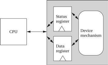
Figure 3.1 Structure of a typical I/O device.
Some registers may be read-only, such as a status register that indicates when the device is done, while others may be readable or writable.
Application Example 3.1 describes a classic I/O device.
Application Example 3.1 The 8251 UART
The 8251 UART (Universal Asynchronous Receiver/Transmitter) [Int82] is the original device used for serial communications, such as the serial port connections on PCs. The 8251 was introduced as a stand-alone integrated circuit for early microprocessors. Today, its functions are typically subsumed by a larger chip, but these more advanced devices still use the basic programming interface defined by the 8251.
The UART is programmable for a variety of transmission and reception parameters. However, the basic format of transmission is simple. Data are transmitted as streams of characters in this form:
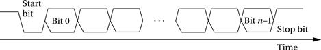
Every character starts with a start bit (a 0) and a stop bit (a 1). The start bit allows the receiver to recognize the start of a new character; the stop bit ensures that there will be a transition at the start of the stop bit. The data bits are sent as high and low voltages at a uniform rate. That rate is known as the baud rate; the period of one bit is the inverse of the baud rate.
Before transmitting or receiving data, the CPU must set the UART’s mode register to correspond to the data line’s characteristics. The parameters for the serial port are familiar from the parameters for a serial communications program:
• mode[1:0]: mode and baud rate
• 01: asynchronous mode, no clock prescaler
• 10: asynchronous mode, 16x prescaler
• 11: asynchronous mode, 64x prescaler
Setting bits in the command register tells the UART what to do:
The status register shows the state of the UART and transmission:
• status [0]: transmitter ready
• status [2]: transmission complete
The UART includes transmit and receive buffer registers. It also includes registers for synchronous mode characters.
The Transmitter Ready output indicates that the transmitter is ready to accept a data character; the Transmitter Empty signal goes high when the UART has no characters to send. On the receiver side, the Receiver Ready pin goes high when the UART has a character ready to be read by the CPU.
3.2.2 Input and Output Primitives
Microprocessors can provide programming support for input and output in two ways: I/O instructions and memory-mapped I/O. Some architectures, such as the Intel x86, provide special instructions (in and out in the case of the Intel x86) for input and output. These instructions provide a separate address space for I/O devices.
But the most common way to implement I/O is by memory mapping—even CPUs that provide I/O instructions can also implement memory-mapped I/O. As the name implies, memory-mapped I/O provides addresses for the registers in each I/O device. Programs use the CPU’s normal read and write instructions to communicate with the devices.
Example 3.1 illustrates memory-mapped I/O on the ARM.
Example 3.1 Memory-Mapped I/O on ARM
We can use the EQU pseudo-op to define a symbolic name for the memory location of our I/O device:
DEV1 EQU 0x1000
Given that name, we can use the following standard code to read and write the device register:
LDR r1,#DEV1 ; set up device address
LDR r0,[r1] ; read DEV1
LDR r0,#8 ; set up value to write
STR r0,[r1] ; write 8 to device
How can we directly write I/O devices in a high-level language like C? When we define and use a variable in C, the compiler hides the variable’s address from us. But we can use pointers to manipulate addresses of I/O devices. The traditional names for functions that read and write arbitrary memory locations are peek and poke. The peek function can be written in C as:
int peek(char *location) {
return *location; /* de-reference location pointer */
}
The argument to peek is a pointer that is de-referenced by the C * operator to read the location. Thus, to read a device register we can write:
#define DEV1 0x1000
…
dev_status = peek(DEV1); /* read device register */
The poke function can be implemented as:
void poke(char *location, char newval) {
(*location) = newval; /* write to location */
}
To write to the status register, we can use the following code:
poke(DEV1,8); /* write 8 to device register */
These functions can, of course, be used to read and write arbitrary memory locations, not just devices.
3.2.3 Busy-Wait I/O
The simplest way to communicate with devices in a program is busy-wait I/O. Devices are typically slower than the CPU and may require many cycles to complete an operation. If the CPU is performing multiple operations on a single device, such as writing several characters to an output device, then it must wait for one operation to complete before starting the next one. (If we try to start writing the second character before the device has finished with the first one, for example, the device will probably never print the first character.) Asking an I/O device whether it is finished by reading its status register is often called polling.
Example 3.2 illustrates busy-wait I/O.
Example 3.2 Busy-Wait I/O Programming
In this example we want to write a sequence of characters to an output device. The device has two registers: one for the character to be written and a status register. The status register’s value is 1 when the device is busy writing and 0 when the write transaction has completed.
We will use the peek and poke functions to write the busy-wait routine in C. First, we define symbolic names for the register addresses:
#define OUT_CHAR 0x1000 /* output device character register */
#define OUT_STATUS 0x1001 /* output device status register */
The sequence of characters is stored in a standard C string, which is terminated by a null (0) character. We can use peek and poke to send the characters and wait for each transaction to complete:
char *mystring = “Hello, world.” /* string to write */
char *current_char; /* pointer to current position in string */
current_char = mystring; /* point to head of string */
while (*current_char != ‘�’) { /* until null character */
poke(OUT_CHAR,*current_char); /* send character to device */
while (peek(OUT_STATUS) != 0); /* keep checking status */
current_char++; /* update character pointer */
}
The outer while loop sends the characters one at a time. The inner while loop checks the device status—it implements the busy-wait function by repeatedly checking the device status until the status changes to 0.
Example 3.3 illustrates a combination of input and output.
Example 3.3 Copying Characters from Input to Output Using Busy-Wait I/O
We want to repeatedly read a character from the input device and write it to the output device. First, we need to define the addresses for the device registers:
#define IN_DATA 0x1000
#define IN_STATUS 0x1001
#define OUT_DATA 0x1100
#define OUT_STATUS 0x1101
The input device sets its status register to 1 when a new character has been read; we must set the status register back to 0 after the character has been read so that the device is ready to read another character. When writing, we must set the output status register to 1 to start writing and wait for it to return to 0. We can use peek and poke to repeatedly perform the read/write operation:
while (TRUE) { /* perform operation forever */
/* read a character into achar */
while (peek(IN_STATUS) == 0); /* wait until ready */
achar = (char)peek(IN_DATA); /* read the character */
/* write achar */
poke(OUT_DATA,achar);
poke(OUT_STATUS,1); /* turn on device */
while (peek(OUT_STATUS) != 0); /* wait until done */
}
3.2.4 Interrupts
Basics
Busy-wait I/O is extremely inefficient—the CPU does nothing but test the device status while the I/O transaction is in progress. In many cases, the CPU could do useful work in parallel with the I/O transaction:
• computation, as in determining the next output to send to the device or processing the last input received, and;
To allow parallelism, we need to introduce new mechanisms into the CPU.
The interrupt mechanism allows devices to signal the CPU and to force execution of a particular piece of code. When an interrupt occurs, the program counter’s value is changed to point to an interrupt handler routine (also commonly known as a device driver) that takes care of the device: writing the next data, reading data that have just become ready, and so on. The interrupt mechanism of course saves the value of the PC at the interruption so that the CPU can return to the program that was interrupted. Interrupts therefore allow the flow of control in the CPU to change easily between different contexts, such as a foreground computation and multiple I/O devices.
As shown in Figure 3.2, the interface between the CPU and I/O device includes several signals for interrupting:
• the I/O device asserts the interrupt request signal when it wants service from the CPU;
• the CPU asserts the interrupt acknowledge signal when it is ready to handle the I/O device’s request.
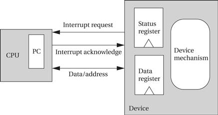
Figure 3.2 The interrupt mechanism.
The I/O device’s logic decides when to interrupt; for example, it may generate an interrupt when its status register goes into the ready state. The CPU may not be able to immediately service an interrupt request because it may be doing something else that must be finished first—for example, a program that talks to both a high-speed disk drive and a low-speed keyboard should be designed to finish a disk transaction before handling a keyboard interrupt. Only when the CPU decides to acknowledge the interrupt does the CPU change the program counter to point to the device’s handler. The interrupt handler operates much like a subroutine, except that it is not called by the executing program. The program that runs when no interrupt is being handled is often called the foreground program; when the interrupt handler finishes, running in the background, it returns to the foreground program, wherever processing was interrupted.
Before considering the details of how interrupts are implemented, let’s look at the interrupt style of processing and compare it to busy-wait I/O. Example 3.4 uses interrupts as a basic replacement for busy-wait I/O.
Example 3.4 Copying Characters from Input to Output with Basic Interrupts
As with Example 3.3, we repeatedly read a character from an input device and write it to an output device. We assume that we can write C functions that act as interrupt handlers. Those handlers will work with the devices in much the same way as in busy-wait I/O by reading and writing status and data registers. The main difference is in handling the output—the interrupt signals that the character is done, so the handler doesn’t have to do anything.
We will use a global variable achar for the input handler to pass the character to the foreground program. Because the foreground program doesn’t know when an interrupt occurs, we also use a global Boolean variable, gotchar, to signal when a new character has been received. Here is the code for the input and output handlers:
void input_handler() { /* get a character and put in global */
achar = peek(IN_DATA); /* get character */
gotchar = TRUE; /* signal to main program */
poke(IN_STATUS,0); /* reset status to initiate next transfer */
}
void output_handler() { /* react to character being sent */
/* don’t have to do anything */
}
The main program is reminiscent of the busy-wait program. It looks at gotchar to check when a new character has been read and then immediately sends it out to the output device.
main() {
while (TRUE) { /* read then write forever */
if (gotchar) { /* write a character */
poke(OUT_DATA,achar); /* put character in device */
poke(OUT_STATUS,1); /* set status to initiate write */
gotchar = FALSE; /* reset flag */
}
}
}
The use of interrupts has made the main program somewhat simpler. But this program design still does not let the foreground program do useful work. Example 3.5 uses a more sophisticated program design to let the foreground program work completely independently of input and output.
Example 3.5 Copying Characters from Input to Output with Interrupts and Buffers
Because we don’t need to wait for each character, we can make this I/O program more sophisticated than the one in Example 3.4. Rather than reading a single character and then writing it, the program performs reads and writes independently. We will use an elastic buffer to hold the characters. The read and write routines communicate through the global variables used to implement the elastic buffer:
• A character string io_buf will hold a queue of characters that have been read but not yet written.
• A pair of integers buf_start and buf_end will point to the first and last characters read.
• An integer error will be set to 0 whenever io_buf overflows.
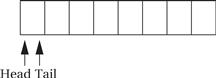
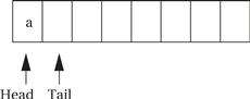
The elastic buffer allows the input and output devices to run at different rates. The queue io_buf acts as a wraparound buffer—we add characters to the tail when an input is received and take characters from the tail when we are ready for output. The head and tail wrap around the end of the buffer array to make most efficient use of the array. Here is the situation at the start of the program’s execution, where the tail points to the first available character and the head points to the ready character. As seen below, because the head and tail are equal, we know that the queue is empty.
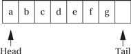
When the first character is read, the tail is incremented after the character is added to the queue, leaving the buffer and pointers looking like the following:
When the buffer is full, we leave one character in the buffer unused. As the next figure shows, if we added another character and updated the tail buffer (wrapping it around to the head of the buffer), we would be unable to distinguish a full buffer from an empty one.
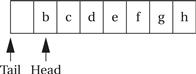
Here is what happens when the output goes past the end of io_buf:
This code implements the elastic buffer, including the declarations for the above global variables and some service routines for adding and removing characters from the queue. Because interrupt handlers are regular code, we can use subroutines to structure code just as with any program.
#define BUF_SIZE 8
char io_buf[BUF_SIZE]; /* character buffer */
int buf_head = 0, buf_tail = 0; /* current position in buffer */
int error = 0; /* set to 1 if buffer ever overflows */
void empty_buffer() { /* returns TRUE if buffer is empty */
buf_head == buf_tail;
}
void full_buffer() { /* returns TRUE if buffer is full */
(buf_tail+1) % BUF_SIZE == buf_head ;
}
int nchars() { /* returns the number of characters in the buffer */
if (buf_head >= buf_tail) return buf_head – buf_tail;
else return BUF_SIZE – buf_tail – buf_head;
}
void add_char(char achar) { /* add a character to the buffer head */
io_buf[buf_tail++] = achar;
/* check pointer */
if (buf_tail == BUF_SIZE)
buf_tail = 0;
}
char remove_char() { /* take a character from the buffer head */
char achar;
achar = io_buf[buf_head++];
/* check pointer */
if (buf_head == BUF_SIZE)
buf_head = 0;
}
Assume that we have two interrupt handling routines defined in C, input_handler for the input device and output_handler for the output device. These routines work with the device in much the same way as did the busy-wait routines. The only complication is in starting the output device: If io_buf has characters waiting, the output driver can start a new output transaction by itself. But if there are no characters waiting, an outside agent must start a new output action whenever the new character arrives. Rather than force the foreground program to look at the character buffer, we will have the input handler check to see whether there is only one character in the buffer and start a new transaction.
Here is the code for the input handler:
#define IN_DATA 0x1000
#define IN_STATUS 0x1001
void input_handler() {
char achar;
if (full_buffer()) /* error */
error = 1;
else { /* read the character and update pointer */
achar = peek(IN_DATA); /* read character */
add_char(achar); /* add to queue */
}
poke(IN_STATUS,0); /* set status register back to 0 */
/* if buffer was empty, start a new output transaction */
if (nchars() == 1) { /* buffer had been empty until this interrupt */
poke(OUT_DATA,remove_char()); /* send character */
poke(OUT_STATUS,1); /* turn device on */
}
}
#define OUT_DATA 0x1100
#define OUT_STATUS 0x1101
void output_handler() {
if (!empty_buffer()) { /* start a new character */
poke(OUT_DATA,remove_char()); /* send character */
poke(OUT_STATUS,1); /* turn device on */
}
}
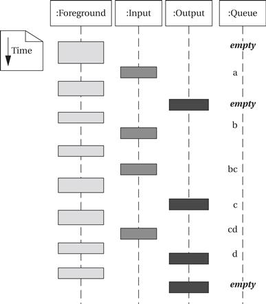
The foreground program does not need to do anything—everything is taken care of by the interrupt handlers. The foreground program is free to do useful work as it is occasionally interrupted by input and output operations. The following sample execution of the program in the form of a UML sequence diagram shows how input and output are interleaved with the foreground program. (We have kept the last input character in the queue until output is complete to make it clearer when input occurs.) The simulation shows that the foreground program is not executing continuously, but it continues to run in its regular state independent of the number of characters waiting in the queue.
Interrupts allow a lot of concurrency, which can make very efficient use of the CPU. But when the interrupt handlers are buggy, the errors can be very hard to find. The fact that an interrupt can occur at any time means that the same bug can manifest itself in different ways when the interrupt handler interrupts different segments of the foreground program.
Example 3.6 illustrates the problems inherent in debugging interrupt handlers.
Example 3.6 Debugging Interrupt Code
Assume that the foreground code is performing a matrix multiplication operation y = Ax + b:
for (i = 0; i < M; i++) {
y[i] = b[i];
for (j = 0; j < N; j++)
y[i] = y[i] + A[i,j]*x[j];
}
We use the interrupt handlers of Example 3.6 to perform I/O while the matrix computation is performed, but with one small change: read_handler has a bug that causes it to change the value of j. While this may seem far-fetched, remember that when the interrupt handler is written in assembly language such bugs are easy to introduce. Any CPU register that is written by the interrupt handler must be saved before it is modified and restored before the handler exits. Any type of bug—such as forgetting to save the register or to properly restore it—can cause that register to mysteriously change value in the foreground program.
What happens to the foreground program when j changes value during an interrupt depends on when the interrupt handler executes. Because the value of j is reset at each iteration of the outer loop, the bug will affect only one entry of the result y. But clearly the entry that changes will depend on when the interrupt occurs. Furthermore, the change observed in y depends on not only what new value is assigned to j (which may depend on the data handled by the interrupt code), but also when in the inner loop the interrupt occurs. An interrupt at the beginning of the inner loop will give a different result than one that occurs near the end. The number of possible new values for the result vector is much too large to consider manually—the bug can’t be found by enumerating the possible wrong values and correlating them with a given root cause. Even recognizing the error can be difficult—for example, an interrupt that occurs at the very end of the inner loop will not cause any change in the foreground program’s result. Finding such bugs generally requires a great deal of tedious experimentation and frustration.
The CPU implements interrupts by checking the interrupt request line at the beginning of execution of every instruction. If an interrupt request has been asserted, the CPU does not fetch the instruction pointed to by the PC. Instead the CPU sets the PC to a predefined location, which is the beginning of the interrupt handling routine. The starting address of the interrupt handler is usually given as a pointer—rather than defining a fixed location for the handler, the CPU defines a location in memory that holds the address of the handler, which can then reside anywhere in memory.
Interrupts and subroutines
Because the CPU checks for interrupts at every instruction, it can respond quickly to service requests from devices. However, the interrupt handler must return to the foreground program without disturbing the foreground program’s operation. Because subroutines perform a similar function, it is natural to build the CPU’s interrupt mechanism to resemble its subroutine function. Most CPUs use the same basic mechanism for remembering the foreground program’s PC as is used for subroutines. The subroutine call mechanism in modern microprocessors is typically a stack, so the interrupt mechanism puts the return address on a stack; some CPUs use the same stack as for subroutines while others define a special stack. The use of a procedure-like interface also makes it easier to provide a high-level language interface for interrupt handlers. The details of the C interface to interrupt handling routines vary both with the CPU and the underlying support software.
Priorities and Vectors
Providing a practical interrupt system requires having more than a simple interrupt request line. Most systems have more than one I/O device, so there must be some mechanism for allowing multiple devices to interrupt. We also want to have flexibility in the locations of the interrupt handling routines, the addresses for devices, and so on. There are two ways in which interrupts can be generalized to handle multiple devices and to provide more flexible definitions for the associated hardware and software:
• interrupt priorities allow the CPU to recognize some interrupts as more important than others, and
• interrupt vectors allow the interrupting device to specify its handler.
Prioritized interrupts not only allow multiple devices to be connected to the interrupt line but also allow the CPU to ignore less important interrupt requests while it handles more important requests. As shown in Figure 3.3, the CPU provides several different interrupt request signals, shown here as L1, L2, up to Ln. Typically, the lower-numbered interrupt lines are given higher priority, so in this case, if devices 1, 2, and n all requested interrupts simultaneously, 1’s request would be acknowledged because it is connected to the highest-priority interrupt line. Rather than provide a separate interrupt acknowledge line for each device, most CPUs use a set of signals that provide the priority number of the winning interrupt in binary form (so that interrupt level 7 requires 3 bits rather than 7). A device knows that its interrupt request was accepted by seeing its own priority number on the interrupt acknowledge lines.
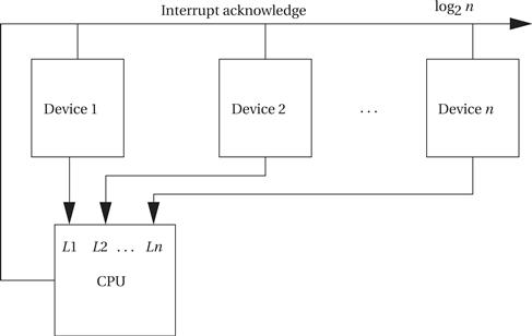
Figure 3.3 Prioritized device interrupts.
How do we change the priority of a device? Simply by connecting it to a different interrupt request line. This requires hardware modification, so if priorities need to be changeable, removable cards, programmable switches, or some other mechanism should be provided to make the change easy.
The priority mechanism must ensure that a lower-priority interrupt does not occur when a higher-priority interrupt is being handled. The decision process is known as masking. When an interrupt is acknowledged, the CPU stores in an internal register the priority level of that interrupt. When a subsequent interrupt is received, its priority is checked against the priority register; the new request is acknowledged only if it has higher priority than the currently pending interrupt. When the interrupt handler exits, the priority register must be reset. The need to reset the priority register is one reason why most architectures introduce a specialized instruction to return from interrupts rather than using the standard subroutine return instruction.
Power-down interrupts
The highest-priority interrupt is normally called the nonmaskable interrupt or NMI. The NMI cannot be turned off and is usually reserved for interrupts caused by power failures—a simple circuit can be used to detect a dangerously low power supply, and the NMI interrupt handler can be used to save critical state in nonvolatile memory, turn off I/O devices to eliminate spurious device operation during power-down,and so on.
Most CPUs provide a relatively small number of interrupt priority levels, such as eight. While more priority levels can be added with external logic, they may not be necessary in all cases. When several devices naturally assume the same priority (such as when you have several identical keypads attached to a single CPU), you can combine polling with prioritized interrupts to efficiently handle the devices. As shown in Figure 3.4, you can use a small amount of logic external to the CPU to generate an interrupt whenever any of the devices you want to group together request service. The CPU will call the interrupt handler associated with this priority; that handler does not know which of the devices actually requested the interrupt. The handler uses software polling to check the status of each device: In this example, it would read the status registers of 1, 2, and 3 to see which of them is ready and requesting service.
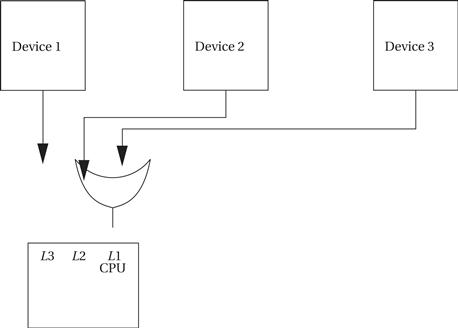
Figure 3.4 Using polling to share an interrupt over several devices.
Example 3.7 Illustrates how priorities affect the order in which I/O requests are handled.
Example 3.7 I/O with Prioritized Interrupts
Assume that we have devices A, B, and C. A has priority 1 (highest priority), B priority 2, and C priority 3. This UML sequence diagram shows which interrupt handler is executing as a function of time for a sequence of interrupt requests:
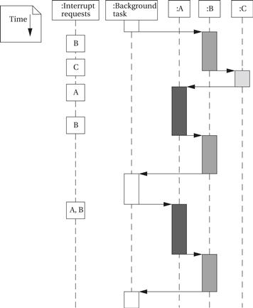
In each case, an interrupt handler keeps running until either it is finished or a higher-priority interrupt arrives. The C interrupt, although it arrives early, does not finish for a long time because interrupts from both A and B intervene—system design must take into account the worst-case combinations of interrupts that can occur to ensure that no device goes without service for too long. When both A and B interrupt simultaneously, A’s interrupt gets priority; when A’s handler is finished, the priority mechanism automatically answers B’s pending interrupt.
Vectors provide flexibility in a different dimension, namely, the ability to define the interrupt handler that should service a request from a device. Figure 3.5 shows the hardware structure required to support interrupt vectors. In addition to the interrupt request and acknowledge lines, additional interrupt vector lines run from the devices to the CPU. After a device’s request is acknowledged, it sends its interrupt vector over those lines to the CPU. The CPU then uses the vector number as an index in a table stored in memory as shown in Figure 3.5. The location referenced in the interrupt vector table by the vector number gives the address of the handler.
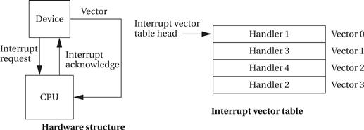
Figure 3.5 Interrupt vectors.
There are two important things to notice about the interrupt vector mechanism. First, the device, not the CPU, stores its vector number. In this way, a device can be given a new handler simply by changing the vector number it sends, without modifying the system software. For example, vector numbers can be changed by programmable switches. The second thing to notice is that there is no fixed relationship between vector numbers and interrupt handlers. The interrupt vector table allows arbitrary relationships between devices and handlers. The vector mechanism provides great flexibility in the coupling of hardware devices and the software routines that service them.
Most modern CPUs implement both prioritized and vectored interrupts. Priorities determine which device is serviced first, and vectors determine what routine is used to service the interrupt. The combination of the two provides a rich interface between hardware and software:
Interrupt Overhead
Now that we have a basic understanding of the interrupt mechanism, we can consider the complete interrupt handling process. Once a device requests an interrupt, some steps are performed by the CPU, some by the device, and others by software:
1. CPU: The CPU checks for pending interrupts at the beginning of an instruction. It answers the highest-priority interrupt, which has a higher priority than that given in the interrupt priority register.
2. Device: The device receives the acknowledgment and sends the CPU its interrupt vector.
3. CPU: The CPU looks up the device handler address in the interrupt vector table using the vector as an index. A subroutine-like mechanism is used to save the current value of the PC and possibly other internal CPU state, such as general-purpose registers.
4. Software: The device driver may save additional CPU state. It then performs the required operations on the device. It then restores any saved state and executes the interrupt return instruction.
5. CPU: The interrupt return instruction restores the PC and other automatically saved states to return execution to the code that was interrupted.
Interrupts do not come without a performance penalty. In addition to the execution time required for the code that talks directly to the devices, there is execution time overhead associated with the interrupt mechanism:
• The interrupt itself has overhead similar to a subroutine call. Because an interrupt causes a change in the program counter, it incurs a branch penalty. In addition, if the interrupt automatically stores CPU registers, that action requires extra cycles, even if the state is not modified by the interrupt handler.
• In addition to the branch delay penalty, the interrupt requires extra cycles to acknowledge the interrupt and obtain the vector from the device.
• The interrupt handler will, in general, save and restore CPU registers that were not automatically saved by the interrupt.
• The interrupt return instruction incurs a branch penalty as well as the time required to restore the automatically saved state.
The time required for the hardware to respond to the interrupt, obtain the vector, and so on cannot be changed by the programmer. In particular, CPUs vary quite a bit in the amount of internal state automatically saved by an interrupt. The programmer does have control over what state is modified by the interrupt handler and therefore it must be saved and restored. Careful programming can sometimes result in a small number of registers used by an interrupt handler, thereby saving time in maintaining the CPU state. However, such tricks usually require coding the interrupt handler in assembly language rather than a high-level language.
Interrupts in ARM
ARM7 supports two types of interrupts: fast interrupt requests (FIQs) and interrupt requests (IRQs). An FIQ takes priority over an IRQ. The interrupt table is always kept in the bottom memory addresses, starting at location 0. The entries in the table typically contain subroutine calls to the appropriate handler.
The ARM7 performs the following steps when responding to an interrupt [ARM99B]:
• saves the appropriate value of the PC to be used to return,
• copies the CPSR into an SPSR (saved program status register),
When leaving the interrupt handler, the handler should:
The worst-case latency to respond to an interrupt includes the following components:
• two cycles to synchronize the external request,
• up to 20 cycles to complete the current instruction,
This adds up to 27 clock cycles. The best-case latency is 4 clock cycles.
Interrupts in C55x
Interrupts in the C55x [Tex04] take at least 7 clock cycles. In many situations, they take 13 clock cycles.
• A maskable interrupt is processed in several steps once the interrupt request is sent to the CPU:
• The interrupt flag register (IFR) corresponding to the interrupt is set.
• The interrupt enable register (IER) is checked to ensure that the interrupt is enabled.
• The interrupt mask register (INTM) is checked to be sure that the interrupt is not masked.
• The interrupt flag register (IFR) corresponding to the flag is cleared.
• Appropriate registers are saved as context.
• INTM is set to 1 to disable maskable interrupts.
• DGBM is set to 1 to disable debug events.
• EALLOW is set to 0 to disable access to non-CPU emulation registers.
• A branch is performed to the interrupt service routine (ISR).
The C55x provides two mechanisms—fast-return and slow-return—to save and restore registers for interrupts and other context switches. Both processes save the return address and loop context registers. The fast-return mode uses RETA to save the return address and CFCT for the loop context bits. The slow-return mode, in contrast, saves the return address and loop context bits on the stack.
Interrupts in PIC16F
The PIC16F recognizes two types of interrupts. Synchronous interrupts generally occur from sources inside the CPU. Asynchronous interrupts are generally triggered from outside the CPU. The INTCON register contains the major control bits for the interrupt system. The Global Interrupt Enable bit GIE is used to allow all unmasked interrupts. The Peripheral Interrupt Enable bit PEIE enables/disables interrupts from peripherals. The TMR0 Overflow Interrupt Enable bit enables or disables the timer 0 overflow interrupt. The INT External Interrupt Enable bit enables/disables the INT external interrupts. Peripheral Interrupt Flag registers PIR1 and PIR2 hold flags for peripheral interrupts.
The RETFIE instruction is used to return from an interrupt routine. This instruction clears the GIE bit, re-enabling pending interrupts.
The latency of synchronous interrupts is 3TCY (where TCY is the length of an instruction) while the latency for asynchronous interrupts is 3 to 3.75TCY. One-cycle and two-cycle instructions have the same interrupt latencies.