
Further reading
As with instruction sets, the ARM and C55x manuals provide good descriptions of exceptions, memory management, and caches for those processors. Patterson and Hennessy [Pat98] provide a thorough description of computer architecture, including pipelining, caches, and memory management.
Questions
Q3-1 Why do most computer systems use memory-mapped I/O?
Q3-2 Why do most programs use interrupt-driven I/O over busy/wait?
Q3-3 Write ARM code that tests a register at location ds1 and continues execution only when the register is nonzero.
Q3-4 Write ARM code that waits for the low-order bit of device register ds1 to become 1 and then reads a value from register dd1.
Q3-5 Implement peek() and poke() in assembly language for ARM.
Q3-6 Draw a UML sequence diagram for a busy-wait read of a device. The diagram should include the program running on the CPU and the device.
Q3-7 Draw a UML sequence diagram for a busy-wait write of a device. The diagram should include the program running on the CPU and the device.
Q3-8 Draw a UML sequence diagram for copying characters from an input to an output device using busy-wait I/O. The diagram should include the two devices and the two busy-wait I/O handlers.
Q3-9 When would you prefer to use busy-wait I/O over interrupt-driven I/O?
Q3-10 If you could only have one of vectors or priorities in your interrupt system, which would you rather have?
Q3-11 Draw a UML sequence diagram for an interrupt-driven read of a device. The diagram should include the background program, the handler, and the device.
Q3-12 Draw a UML sequence diagram for an interrupt-driven write of a device. The diagram should include the background program, the handler, and the device.
Q3-13 Draw a UML sequence diagram for a vectored interrupt-driven read of a device. The diagram should include the background program, the interrupt vector table, the handler, and the device.
Q3-14 Draw a UML sequence diagram for copying characters from an input to an output device using interrupt-driven I/O. The diagram should include the two devices and the two I/O handlers.
Q3-15 Draw a UML sequence diagram of a higher-priority interrupt that happens during a lower-priority interrupt handler. The diagram should include the device, the two handlers, and the background program.
Q3-16 Draw a UML sequence diagram of a lower-priority interrupt that happens during a higher-priority interrupt handler. The diagram should include the device, the two handlers, and the background program.
Q3-17 Draw a UML sequence diagram of a nonmaskable interrupt that happens during a low-priority interrupt handler. The diagram should include the device, the two handlers, and the background program.
Q3-18 Draw a UML state diagram for the steps performed by an ARM7 when it responds to an interrupt.
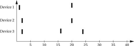
Q3-19 Three devices are attached to a microprocessor: Device 1 has highest priority and device 3 has lowest priority. Each device’s interrupt handler takes 5 time units to execute. Show what interrupt handler (if any) is executing at each time given the sequence of device interrupts displayed below.
Q3-20 Draw a UML sequence diagram that shows how an ARM processor goes into supervisor mode. The diagram should include the supervisor mode program and the user mode program.
Q3-21 Give three examples of typical types of exceptions handled by CPUs.
Q3-22 What are traps used for?
Q3-23 Draw a UML sequence diagram that shows how an ARM processor handles a floating-point exception. The diagram should include the user program, the exception handler, and the exception handler table.
Q3-24 Provide examples of how each of the following can occur in a typical program:
Q3-25 What is the average memory access time of a machine whose hit rate is 96%, with a cache access time of 3 ns and a main memory access time of 70 ns?
Q3-26 If we want an average memory access time of 6.5 ns, our cache access time is 5 ns, and our main memory access time is 80 ns, what cache hit rate must we achieve?
Q3-27 In the two-way, set-associative cache with four banks of Example 3.8, show the state of the cache after each memory access, as was done for the direct-mapped cache. Use an LRU replacement policy.
Q3-28 The following code is executed by an ARM processor with each instruction executed exactly once:
MOV r0,#0 ; use r0 for i, set to 0
LDR r1,#10 ; get value of N for loop termination test
MOV r2,#0 ; use r2 for f, set to 0
ADR r3,c ; load r3 with address of base of c array
ADR r5,x ; load r5 with address of base of x array
; loop test
loop CMP r0,r1
BGE loopend ; if i >= N, exit loop
; loop body
LDR r4,[r3,r0] ; get value of c[i]
LDR r6,[r5,r0] ; get value of x[i]
MUL r4,r4,r6 ; compute c[i]*x[i]
ADD r2,r2,r4 ; add into running sum f
; update loop counter
ADD r0,r0,#1 ; add 1 to i
B loop ; unconditional branch to top of loop
Show the contents of the instruction cache for these configurations, assuming each line holds one ARM instruction:
Q3-29 Show a UML state diagram for a paged address translation using a flat page table.
Q3-30 Show a UML state diagram for a paged address translation using a three-level, tree-structured page table.
Q3-31 What are the stages in an ARM pipeline?
Q3-32 What are the stages in the C55x pipeline?
Q3-33 What is the difference between latency and throughput?
Q3-34 Draw a pipeline diagram for an ARM7 pipeline’s execution of three fictional instructions: aa, bb, and cc. The aa instruction always requires two cycles to complete the execute stage. The cc instruction takes two cycles to complete the execute stage if the previous instruction was a bb instruction. Draw the pipeline diagram for these sequence of instructions:
Q3-35 Draw two pipeline diagrams showing what happens when an ARM BZ instruction is taken and not taken, respectively.
Q3-36 Name three mechanisms by which a CMOS microprocessor consumes power.
Q3-37 Provide a user-level example of
Q3-38 Why can’t you use the same mechanism to return from a sleep power-saving state as you do from an idle power-saving state?
Lab exercises
L3-1 Write a simple loop that lets you exercise the cache. By changing the number of statements in the loop body, you can vary the cache hit rate of the loop as it executes. If your microprocessor fetches instructions from off-chip memory, you should be able to observe changes in the speed of execution by observing the microprocessor bus.
L3-2 If your CPU has a pipeline that gives different execution times when a branch is taken or not taken, write a program in which these branches take different amounts of time. Use a CPU simulator to observe the behavior of the program.
L3-3 Measure the time required to respond to an interrupt.