
14.8 POLYPHASE DECIMATOR IMPLEMENTATIONS
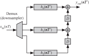
A polyphase decimator splits the high-rate input signals into M low-rate nonoverlapped streams such that each stream is applied to a filter with length N/M. Figure 14.8 shows the splitting of the input data stream into M nonoverlapped streams, and each stream is fed to a low-pass FIR filter. Each filter has the following characteristics:
1. It operates at the longer sample time T′ = MT.
2. The number of filter coefficients is reduced to N/M.
3. Every Mth input sample is used.
Figure 14.8 Polyphase implementation of a decimator for the case M = 3.
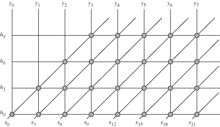
In order to get a dependence graph for a polyphase filter, we break up the dependence graph of Fig. 14.1 into M = 3 dependence graphs. Figure 14.9 shows the dependence graph corresponding to the stream feeding the filter h0(nT′). Each dependence graph corresponds to one branch of the polyphase filter structure of Fig. 14.8. Table 14.1 shows the filter coefficients associated with the filter whose impulse transfer function is hi(nT) and also shows the stream of input data samples allocated to it. In general, polyphase filter hi(nT) (0 ≤ i < M) is fed the ith downsampled stream and uses the filter coefficient hk+jM where 0 ≤ j < N/M and is given by
(14.26)
![]()
Table 14.1 Filter Coefficients and Input Samples Associated with Each Polyphase Filter for the Case M = 3 and N = 12
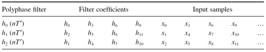
Figure 14.9 Dependence graph for polyphase filter h0(nT′) for an M-to-1 decimator for the case when M = 3 and N = 12.
The advantages of polyphase filters are that each filter operates at the slower rate of MT and its length is N/M. We can use the different 1-D FIR filter structures discussed previously to realize the polyphase decimator.