
2.3 PARALLELIZING ALU STRUCTURE
Parallel structure implies using several copies of the same hardware in the ALU. An example of use of parallelism to enhance performance is the multiplication operation. Before the days of very large-scale integration (VLSI), early computers could not afford to multiply numbers using a dedicated multiplier. They used the adder in the ALU to do multiplication through the add–shift technique. Assume the two numbers to be multiplied, a and b, have the following binary representations:
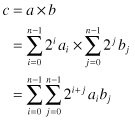
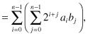
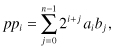
where ai, bi = {0, 1}. Equation 2.2 could be thought of as the parallel implementation of the multiplication operation. Essentially, we are forming all the partial products aibj and then add them together with the proper binary weights. Equation 2.3 is the bit-serial implementation. Here we add the partial products over two stages first along the j index then add the results over the i index. This will be explained shortly. Some authors refer to this operation as serial/parallel multiplication since 1 bit is used to multiply the other word.
Figure 2.1 shows the bit-serial multiplication technique for the case n = 4. The multiplicand b is stored in a register and the multiplier a is stored in a shift register so that at each clock cycle, 1 bit is read out starting with the least significant bit (LSB). At the first clock cycle, a partial product pp0 is formed
(2.4)
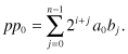
Figure 2.1 Bit-serial binary multiplication for the case n = 4.
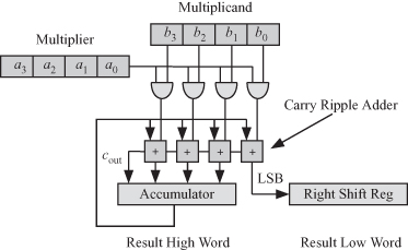
The LSB of this partial product is extracted and stored in a right shift register, as shown at the bottom right of the figure. The remaining bits of pp0 are stored in an accumulator to be added to the next partial product, pp1. In general, at clock cycle i, we generate partial product ppi:
(2.5)
and the accumulator performs the operation
(2.6)
![]()
where Acci is the content of the accumulator at the end of the ith clock cycle and ![]() is the ith partial product with the LSB removed. After n = 4 clock cycles, the 2n-bit product a × b is available with the n-bit high word stored in the accumulator and the n-bit low word stored in the right shift register. The time required to perform the bit-serial multiplication is estimated roughly as
is the ith partial product with the LSB removed. After n = 4 clock cycles, the 2n-bit product a × b is available with the n-bit high word stored in the accumulator and the n-bit low word stored in the right shift register. The time required to perform the bit-serial multiplication is estimated roughly as
(2.7)
![]()
where Tadd is the n-bit carry ripple adder delay and Tfa is the 1-bit full adder delay.
For such a processor, the clock duration is dictated by the carry ripple adder delay, and we have Tclk = Tadd. Simple ALUs used this iterative multiplication technique to do many more operations that need several multiplication operations such as division and elementary function evaluation (e.g., trigonometric and hyperbolic functions and square root). In fact, the coordinate rotation digital computer (CORDIC) algorithm was invented in the late 1950s for elementary function evaluation without the need for multipliers [7, 8]. However, this CORDIC algorithm is inherently bit-serial and required many clock cycles to complete.
Thanks to VLSI technology, it is now feasible to incorporate a parallel multiplier in the ALU and thereby to speed up the processor. Figure 2.2 shows the parallel multiplication technique for the case n = 4. Figure 2.2a shows the parallel multiplier structure. The multiplicand b is stored in a register at the top, and the multiplier a is stored in a register at the left of the figure. Most of the parallel multiplier structure is composed of a two-dimensional (2-D) array of cells that generate the partial product bits simultaneously. At the bottom of Fig. 2.2a is a carry ripple adder. The gray squares with the a + symbol indicate a 1-bit full adder. The gray circles with a + and × symbols indicate an AND gate connected to a 1-bit full adder as shown in more detail in Fig. 2.2b.
Figure 2.2 Parallel binary multiplication for the case n = 4. (a) The multiplier structure. (b) The details of the gray circles with + and × symbols.
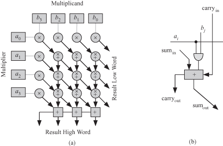
The array of AND gates is responsible for generating all the bits of the partial products aibj. The array of adders is responsible for adding up all these partial products. The diagonal lines indicated lines of equal binary weight, and the vertical lines indicate the path for the carry out signals. The time required to perform the parallel multiplication operation is
(2.8)
![]()
We see that the time required for parallel multiplication is n times smaller than the bit-serial multiplication delay. However, this comes at a cost of more hardware. The author developed a parallel CORDIC algorithm (high-performance coordinate rotation digital computer [HCORDIC]) that is faster than the bit-serial CORDIC but relies on the fact that modern ALUs contain a multiplier [5, 6]. Thus the presence of a parallel multiplier speeds up not only the multiplication operation but the evaluation of many elementary functions.