As noted earlier, the grids included with this book fall into two different categories. Grid #1 is useful for creating things like the floor plan for an office building, the shape of an airplane’s wings, or the layout of walls surrounding a castle. Grid #2 is most effective for planning small, studs-out mosaics. The last two allow you to plan the height of a model and include the side view of such things as slopes and plates. You can also use them to plan mosaics or help you design custom-sized arches that you make from inverted slopes. Which grid you use depends on what part of the model you are trying to design. A large model may, in fact, not even fit on a single grid. In that case, you can either use the grid to work out only a portion of the model, or you can simply tape several sheets together until you have enough room to complete your design.
You can and should use two, three, or all four of the different grids when designing a model. For example, if you are sitting down to design the train station model from Chapter 3, you might use Grid #1 to plan the layout of the walls, including the ticket counter and the front door. Grid #2 is, of course, most useful for planning mosaics (see more about mosaics in Chapter 8). Grid #3 is handy for just about any model or even just experimenting with combinations of parts. You might then use Grid #4 to sketch the front of the train station indicating where you plan to put the windows and the bench. Like any tool, the Design Grids are intended to make your life easier, so use them as much or as little as you need.
Because the grids are sized to the exact dimensions of LEGO elements, you can use them effectively in two ways. The first method is to simply sketch out your model on the grid, not worrying about which pieces go where. Then, when you have the basic model drawn out, you can find pieces in your collection that match the shape you’ve created on the grid.
The second way is to draw specific pieces onto the cells in order to see how they look. You might do this if you don’t happen to have a specific piece but are planning on buying some. Or, you might use this method to simply try out some different part combinations without having to get out several of your storage boxes.
The grids aren’t just effective for planning the positions of pieces. You can also use them to test what certain color combinations might look like. To do this, draw the outlines of the pieces with which you want to experiment. Then color them in using colored pencils, crayons, or fine markers. You can even test the look of color combinations for parts you may not yet own. It’s an easy and inexpensive way to figure out what parts you may need for future projects.
There are also spaces provided at the bottom of each grid to fill in the description of the model and the date the design sketch was made. Figure B-7 shows an example of the kind of note you can make for yourself using this part of each grid.
Figure B-7. Descriptions don’t have to be fancy. Jot down just enough information to remind yourself of the purpose of this particular design.
You may want to keep some of your designs in safe place. That way, as you design future projects, you can look back to see your past efforts—what did and did not work.
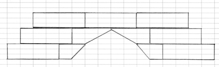
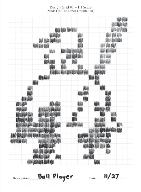
Remember, Grid #1 presents a view just like you’d see if you were looking down on the map of a town. You see things as though you are floating high above in a hot air balloon. You can’t see the sides of any object from this view, only the tops. For example, if you were to draw the Empire State Building micro model (from Chapter 6) onto a copy of Design Grid #1, you would end up with something like the drawing shown in Figure B-8.
You can use this particular grid in several ways. First, you can use it to determine the various heights of layers within the same model. As you can see in Figure B-8, I’ve used various shading techniques to represent different levels of the building. Areas are shaded light and dark gray, other parts are indicated by diagonal lines, and still other portions have been left blank. Each of these different patterns or shades indicates that the height of the model is different than it is in a differently colored/shaded area. This treatment reminds me to pay attention to the changing geometry as I construct the building, and it is also a way that I can represent three dimensions on a two-dimensional diagram.
You can also use Design Grid #1 to plan the outline of something, like we did with the shuttle wings in Chapter 10, or to see the distances between walls within a building, as with the train station example from Chapter 3, or even the distance between two small buildings.
If you’re going to use it for outlining, then it’s really only necessary to draw a line around the outside of the shape and then use the grid to fill in the needed bricks. Figure B-9 shows part of the shuttle wing that we designed back in Chapter 10.
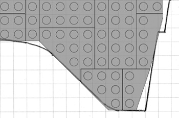
Figure B-9. Using the Design Grids, you can literally piece together a model design by placing real elements on top of your paper sketch.
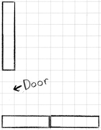
In the case of buildings, you can use the grids to plan where the walls will be and also how features such as doors and windows will fit in. Figure Figure B-10 shows what a portion of the train station walls from Chapter 3 might look like.
Of course another good use for Design Grid #1 is to help plan studs-out mosaics. As I noted in Chapter 8, the studs-out style isn’t as subtle as the studs-up variety, but such mosaics can still be fun to plan and build. See Figure B-11 for a simple example.
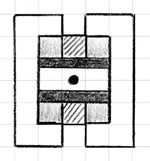
One way of using Grid #2 effectively is to find an image you want to turn into a mosaic. Print out a copy of the grid and a copy of the image on a separate piece of paper. If possible, resize the image to approximately 6 1/2 inches square and center it in the middle of the page. Then, when you set the grid sheet on top of the printout of the image, the two sheets will be aligned. This will, more or less, cause the image to fall within the length and width of the grid itself. To plan your mosaic, simply trace whatever parts of the image you want to reproduce in bricks. In Figure B-12, you can see that I’m beginning to sketch out a simple example.
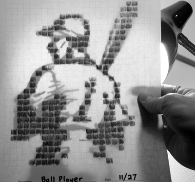
Figure B-12. If possible, try to use lightweight paper when printing out Grid #2. This will allow your image to show through from below.
Note
Refer to Chapter 8 for even more information on using Grid #2.
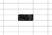
Design Grid #3 represents an entirely different view than you saw on Grids #1 and #2. In this case, you perform the model planning as though you are looking at the bricks and plates from the side. If you were to simply draw a single 1x1 plate, it would look like Figure B-13.
A standard 1x1 brick would then look like Figure B-14.
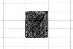
As you can see, each time you want to draw the equivalent of a full-height 1x1 brick, you simply draw a line around three of the cells. You draw longer bricks, such as a 1xN bricks, by extending the top and bottom lines until you have captured the length you need. Figure B-15 shows what a 1x4 arch brick would look like when drawn on this grid. You don’t need to limit yourself to just standard bricks and plates; you can draw other pieces just as easily.
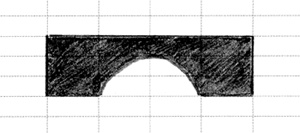
Figure B-15. Parts with complex shapes, such as the arch shown here, can also be easily drawn on the Design Grids.
You can also indicate slopes on this grid by drawing diagonal lines along with lines for the bottom and side of the element (see Figure B-16).
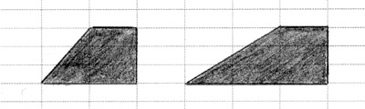
For example, in Figure B-16 you can see a 2x1 45-degree slope and a 3x4 33-degree slope. Notice that the diagonal lines cut across the lines of the grid itself, but that’s to be expected. If you are ever confused about which lines to connect to make the sloped side of the piece, just grab an actual slope from your collection and study where the slanted edge meets the rest of the brick. Don’t forget to leave a flat line at the top to represent where the stud is located.
Once you understand how to use Grid #3, you know how to use Grid #4. The only real difference between the two grids is the way the pages are oriented. As noted earlier, Grid #3 is used in portrait perspective, whereas Grid #4 is in the landscape perspective. You’ll find Grid #3 useful when your model is taller than it is wide. Obviously the opposite is true for Grid #4.
Figure B-17 shows an example of testing a particular combination of parts—to view their final shape—without ever taking a piece out of storage. As you can see, the drawing isn’t perfect, but it can help you make some key construction decisions.