
]>
12
Optical Waves in Anisotropic Crystals
An optical crystal is an anisotopic dielectric and the dielectric tensor of such a crystal in a coordinate system that coincides with the principal axes of the crystal will have zero off-diagonal elements and is given by
The principal refractive indices of the crystal are given by
The crystals are classified as biaxial, uniaxial, or isotropic depending on the number of equalities involving the principal refractive indices:
Properties of wave propagation in isotropic crystals are discussed in Chapter 2. In the following section, we discuss wave propagation in crystals in the order of increasing complexity of analysis [1,2,3].
12.1Wave Propagation in a Biaxial Crystal along the Principal Axes
Let the principal axes be aligned along the Cartesian coordinate system. A uniform plane wave with a harmonic variation in space and time given by
satisfies following equations:
Equation 12.7, Equation 12.8, Equation 12.9, Equation 12.10, Equation 12.11 and Equation 12.12 are obtained from Maxwell’s equations and the constitutive relation for the crystal. From Equations 12.9 and 12.10, we obtain
and from Equations 12.7 and 12.8, we obtain
For the particular case of
we obtain
Therefore, the dispersion relation in this case is given by
The results obtained in this particular case may be stated in words as follows: the propagation of a wave linearly polarized in the direction of a principal axis and propagating along the direction of another principal axis is similar to that of wave propagation in an isotropic case except that the effective refractive index is given by the refractive index in the direction of polarization.
We next consider an example of change of wave polarization by a biaxial crystal. Let the electric field E of a wave propagating in the z-direction in this crystal, at z = 0, be given by
This wave is linearly polarized at 45° (with the x-axis) in the z = 0 plane. If we consider this wave as a superposition of two waves, one with linear polarization in the x-direction and another with linear polarization in the y-direction, then we can write the electric field of this wave at z = d as
Note that the phase of the wave changes with d since nxk0d ≠ nyk0d. Hence, the wave polarization will not remain linear.
12.2Propagation in an Arbitrary Direction
The notation and the formulations in Section 12.2, Section 12.3 and Section 12.4 closely follow that of reference [3]. Let the unit vector in the direction of propagation be designated by ˆe3
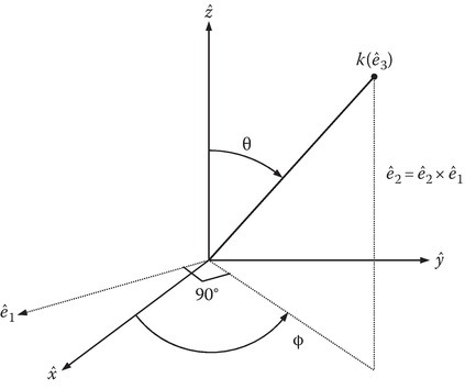
FIGURE 12.1
Orthogonal coordinate system with one coordinate along the wave normal.
Let ˆe1
and
Let
The unit vectors ˆe1,ˆe2,andˆe3
The transformation is easily determined by noting
Similar considerations will lead to the determination of the transformation matrix ˉT
By calculating ˉT−1
where the superscript T stands for the transpose operation. Defining an impermittivity tensor ˉη
where
we obtain
If the elements of ˉηk
From Equations 12.7, 12.8, and 12.37, we obtain
By eliminating all other variables, we can obtain the dispersion relation
where u = ω/k is the phase velocity.
12.3Propagation in an Arbitrary Direction: Uniaxial Crystal
As an example of further calculations, we restrict ourselves to a uniaxial crystal. For this case,
where
Thus,
From Equations 12.42 and Equation 12.46, Equation 12.47 and Equation 12.48, we obtain the following results.
Case 1:
Case 2:
In the first case, the phase velocity is
and in the second case it is
In the latter case, the phase velocity depends on θ.
12.4k-Surface
Let k be the scalar wave number and is given by
where ks is the transverse wave number.
For Case 1,
Figure 12.2a shows this circle in ks − kz plain.
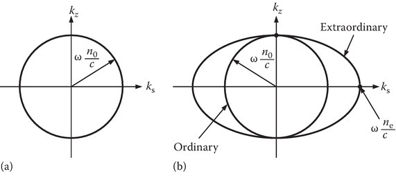
FIGURE 12.2
k-Surface. (a) Ordinary and (b) ordinary and extraordinary.
For Case 2,
which may be written as
Thus, the curve in ks − kz plane is an ellipse as shown in Figure 12.2.
The phase velocity is given by ω/k and for the ordinary wave it is the same for all θ. For the extraordinary wave, ω/k depends on θ, since the k curve is an ellipse. The group velocity for this case can be defined as a vector:
In three-dimensional k-space, we obtain a sphere for the ordinary wave and ellipsoid for the extraordinary wave.
For a uniaxial crystal, the refractive index is the same along the two principal directions (no in x- and y-directions in our notation) and different along the axis (ne along the z-axis) called the optical axis. Note that the refractive index surfaces touch along the kz-axis.
12.5Group Velocity as a Function of Polar Angle
The angle between the optical axis and the wave normal (direction of phase propagation) is the polar angle θ. From Equation 12.58, we obtain
where c is the velocity of light in free space, kz = k cos θ, and ks = k sin θ:
Noting that
Similarly,
The magnitude of the group velocity |ug| is given by
Since ω/k = u,
If the angle of ug with the polar axis is θg, then
If α = θ − θg, then
Note that if θ = 0, then tan α = 0, and α = 0.
If θ = π/2, then tan α = ∞/∞2 = 1/∞ = 0, thus α = 0 (Figure 12.3).
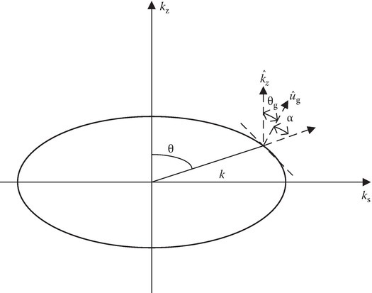
FIGURE 12.3
Various angles for the extraordinary wave.
To find the value of θ so that α is maximum, let tan θ = x, and we have to find x that maximizes x/(1+(n2ox2)/n2e). Differentiating with respect to x and equating to zero (use νdu − udν = 0), we obtain
α is maximum when tan θ = ne/no:
For example, for quartz,
A further approximation can be made for the case no ≈ ne.
For no ≈ ne, tan θ ≈ 1 for α to be maximum.
Hence, θ ≈ 45° for α to be maximum.
From Equation 12.67, we obtain
αmax = 0.334° nearest to the previous answer.
tan (αmax) is proportional to |no − ne|.
12.6Reflection by an Anisotropic Half-Space
When the transmission medium is anisotropic, we have seen that there are two transmitted waves (Figure 12.4). For oblique incidence, each transmitted wave has its own transmission angle. Since the boundary condition is still that kx is conserved for all waves, Snell’s law may be written as
where k1 and k2 are the wave numbers of the respective transmitted waves. We have noted that for the extraordinary wave, the k-surface is not a sphere. In such a case, the value of k depends on the angle of refraction. A graphical interpretation of the technique of obtaining the solution is shown in Figure 12.5.
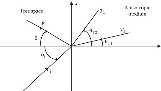
FIGURE 12.4
Reflection and transmission by an anisotropic medium.

FIGURE 12.5
Computation of the angle of transmission.