
]>
Appendix 11A: Faraday Rotation versus Natural Rotation
Equation 11.31 gives the expression for the angle ψ of the linearly polarized wave as it propagates in the magnetoplasma medium. In this appendix, we show how that expression is obtained. We also show an application of this Faraday rotation in measuring the total electron content in the ionosphere [1].
Such a rotation also occurs in chiral medium called natural rotation or optical activity discussed in Section 8.10. However, there is an important difference between Faraday rotation and natural rotation. This aspect is also explained (see Figure 11A.1).

FIGURE 11A.1
Definition of longitudinal propagation.
11A.1Faraday Rotation
At z = 0, consider the electric field of a linearly polarized wave propagating in the z-direction to be
This is an x-polarized (linear) wave. This can be written as a superposition of R and L waves:
Since the wave is propagating in the +z-direction, the wave at z = d can be written as
where
Equation 11A.3 may be written as (see Figure 11A.2)
which is a linearly polarized wave, but it is no longer x-polarized. The electric field traces a straight line but the line at an angle ψF is given by (see Figure 11A.3)

FIGURE 11A.2
The electric field at z = 0.
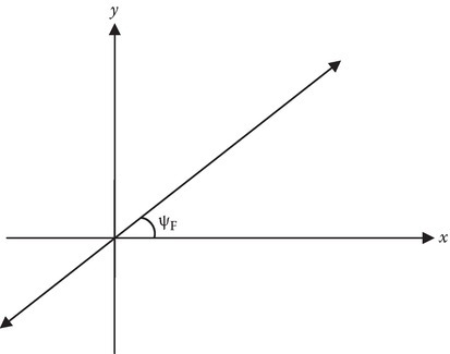
FIGURE 11A.3
The electric field at z = d.
From Equation 11A.4, Equation 11A.5, Equation 11A.6 and Equation 11A.7 and 11A.9, and using the definition of ωp and ωb, we obtain
where q and m are the absolute value of the charge and mass of the electron, respectively, and N0 is the electron density. If the electron density varies with distance and if B0 is approximately constant, the net rotation angle is given by
where the integration is along the propagation path. Measurements of the total electron content in 1 m2 column are made using satellite–earth transmissions, by measuring ψF.
11A.2Natural Rotation and Comparison
Note that the chiral media also cause rotation of linearly polarized wave. In calculating the angle ψ = ψc, we use kcL and kcR instead of kpR and kpL. See Appendix 8A.
However, there is one important difference in the rotation angle for a “round-trip” calculation, for the two cases.
The calculation for a return trip can be made by observing (Figure 11A.4).
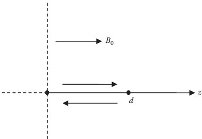
FIGURE 11A.4
Natural rotation.
Let us first consider Faraday rotation.
For a negatively going wave, the direction of B0 and the direction of propagation are 180° apart. The wave numbers kpR and kpL can be obtained by replacing ωb by (−ωb) in Equations 11A.6 and 11A.7. This is tantamount to replacing
and
in Equation 11A.9. Also, since the difference between the z-coordinate of the starting point and the end point is −d, we have to replace d → −d in Equation 11A.9.
Thus, the value of ψF remains unchanged. The rotation angle for a round trip is thus twice that of a one-way trip.
On the other hand, for a chiral media, kcL and kcR are unchanged but d will be replaced by −d. Thus, the rotation angle for the return trip is the same as for the trip except for the sign. The round-trip rotation angle is zero.
Reference
- 1.Inan, S. I. and Inan, S. A., Electromagnetic Waves, Prentice Hall, Upper Saddle River, NJ, 2000.