
]>
Appendix 14A: Electromagnetic Wave Interaction with Moving Bounded Plasmas*
14A.1Introduction
Recent studies on electromagnetic wave interaction with bounded relativistic plasmas have generally neglected oblique incidence and the results have been limited to the case of normal incidence. In a previous article [1], the reflection and transmission of electromagnetic waves obliquely incident on a relativistically moving uniaxial plasma slab was studied, bringing out the nature of oscillations in the reflection coefficient against the normalized slab velocity. The problem was solved in the rest system of the slab and it was seen that as the slab recedes from the incident wave, the angle of reflection as viewed from the observer’s frame turns out to be 90° for some critical slab velocity, thus explaining the zero reflected power at this velocity. This is in agreement with Yeh’s finding [2] for the dielectric half-space moving normal to the interface. However, his observation that beyond this critical point the reflected wave is evanescent seems to be incorrect.
The purpose of this chapter was to unfold the interesting effects that occur beyond the above critical slab velocity. The conclusion drawn is very general and has relevance whenever a plane wave is obliquely incident on a medium moving normal to the interface.
The maxima and minima of the power reflection coefficient as a function of the normalized slab velocity are also shown for electromagnetic waves obliquely incident on an isotropic plasma slab. Both parallel and perpendicular polarizations of the wave are considered.
14A.2Basic Equations
Let the primed quantities be measured in Σ′ which is at rest with respect to the moving plasma slab and the corresponding unprimed quantities with respect to the observer’s frame Σ. Assume that the field quantities in plasma have an exponential variation of the form
where
Using Maxwell’s equations in plasma, one may obtain q′, the root of the dispersion equation, as
In the above equations, S = sin θ, C = cos θ (θ being the angle of incidence), Ω = ω/ωp, and .
Other symbols have their usual meaning [1]. The parameter p has the significance that it transforms the incident wave frequency to the rest system of the plasma. The relations between the primed and unprimed quantities are as given in Reference 1.
The power reflection and transmission coefficients may be put in the form [1]:
in the real range of q′ and
in the imaginary range of q′, where α, A, and B for the two polarizations are given by the following.
Parallel polarization:
Perpendicular polarization:
In the above expressions,
and , λp being the free-space wavelength corresponding to plasma frequency and d′ is the thickness of the plasma slab.
14A.3Numerical Results and Discussion
The power reflection coefficient versus normalized wave frequency (Ω) curves are similar in shape to those given in Reference 3 and hence omitted in this chapter.
The development of the power reflection coefficient as a function of the normalized slab velocity (β) follows the procedure outlined in Reference 1 and the equations giving the maxima and minima in the oscillatory range are listed in Section 14A.3.1.
Although the two types of wave polarization lead to the same result for the limiting case of normal incidence [4,5], it is not so for oblique incidence and numerical results are therefore given for both polarizations taking C = 0.5, dp = 1.0, and Ω = 2.0 (Figures 14A.1 and 14A.2). It is seen that the oscillations decay faster for parallel polarization than for perpendicular polarization. The curve beyond β = (1 – S)/C is shown dashed to bring out the significant point that the reflected wave in this range propagates toward the slab. This is explained as follows.

FIGURE 14A.1
Power reflection coefficient ρ versus normalized slab velocity β for parallel polarized wave. The curve beyond the critical slab velocity [β = (1 − S)/C] represents −ρ and is shown as dashed lines. The significance is that for p > (1 − S)/C the reflected wave propagates along the positive z-axis. (Reprinted with permission from Kalluri, D. and Shrivastava, R.K., Electromagnetic wave interaction with moving bounded plasmas, J. Appl. Phys., 44, 4518–4521, 1973. Copyright 1973, American Institute of Physics.)

FIGURE 14A.2
ρ versus β for perpendicularly polarized wave. The slow oscillations when compared to fast-decaying oscillations in the corresponding curve for parallel polarization is to be noted.
The factor α in Equation 14A.5 has the physical significance that it is the reflected power from a moving mirror and the reflected power for the slab is given by multiplying α by an appropriate term which takes into account that plasma is partly conducting and that the parallel boundaries cause interference of the internally reflected waves. The plot of α versus β is given in Figure 14A.3 (along with the variation of θr and θ′ with β) where the negative value of α beyond β = (1 – S)/C is shown dashed. α is zero at β = (1 – S)/C since the angle of reflection θr[cos−1(C/β′)] as seen in Σ is 90° at this value of β. It is seen that in the range (1 – S)/C < β < C, θr > 90° and α is thus negative. This means that in this range of β, the reflected wave actually travels toward the plasma medium. It is further interesting to note that α continues to represent the reflected power of a moving mirror for C < β < 1. However, in this range, while the incident wave from below never catches the moving mirror, the moving mirror can interact with an existing plane wave above the mirror. The wave is, no doubt, moving away from the mirror, but since the velocity of the mirror is greater than the normal component of the phase velocity of the incident wave, the mirror, so to speak, will be impinging on the free-space wave.
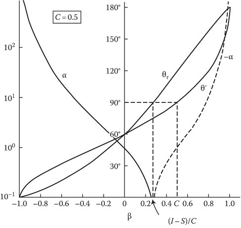
FIGURE 14A.3
θ′, the angle of incidence in Σ′, and θr, the angle of reflection as seen in Σ, plotted as functions of β. α versus β is also shown. α is the factor that represents power reflected from a moving mirror.
The interaction of the incident wave with the plasma slab in the entire range −1 < β < 1 is explained qualitatively in Figures 14A.4 and 14A.5.

FIGURE 14A.4
Geometries explaining the interaction of the wave with the plasma slab qualitatively for the range –1 < β < C. The orientation of the various free-space waves in both Σ and Σ′ is clearly depicted.

FIGURE 14A.5
Geometries explaining the interaction of the wave with the plasma slab for C ≤ β ≤ 1.
Figure 14A.4a depicts the situation in the range –1 < β < (1 – S)/C. The incident wave (I wave) and the reflected wave (R wave) are below the slab, the reflected wave moving away from the slab. The angle of reflection θr continuously increases and becomes 90° at β = (1 – S)/C as noted earlier (Figure 14A.4b). The transmitted wave (T wave) is above the slab. The situation seen in Σ′ is also depicted. At this β, the reflected wave appears to travel parallel to the slab in Σ frame and the normal component of the Poynting’s vector associated with this wave in zero.
In the range (1 – S)/C < β < C, the R wave is still below the slab since the normal component of its phase velocity is less than the slab velocity, but the wave now propagates toward the slab. The observation made by Yeh2 that since θr > 90°, the reflected wave is evanescent is thus in error.
At β = C, the normal component of the phase velocity of the incident wave is equal to the slab velocity, and the wave moves just parallel to the slab interface as seen in Σ′ (Figure 14A.5a). Thus, there is no interaction between the wave and the plasma medium at β = C.
For C < β < 1, the situation in Σ and Σ′ is shown in Figure 14A.5b. The I and R waves are above the slab, moving away from the slab. The T wave, of course, is below the slab, moving toward it.
As is known, the reflected power (ρ, power in the R wave) and transmitted power (τ, power in the T wave) add up to the incident power only at β = 0 and, for other values of β, the conservation of power requires that the excess of the time-averaged power of the generated waves over the incident power must come from the rate of decrease of stored energy and the mechanical power to be put in to maintain the motion against the radiation pressure. Using a detailed energy balance analysis on the lines indicated by Daly and Gruenberg [6], the authors have checked the assumed orientation of the various free-space waves (as given in Figures 14A.4 and 14A.5) for both the lower and upper interfaces of a dielectric slab and this is a sufficient check since the given wave orientations do not depend on the nature of the medium considered.
A similar analysis for the plasma slab, requiring suitable modifications* in the expression for the stored energy and the stress tensor, is currently in progress and will be reported later.
14A.3.1Appendix
The minima in ρ/α occur for p and is given by
The maxima in ρ/α occur for p satisfying the transcendental equation tan A = fpA, where
References
- 1.Kalluri, D. and Shrivastava, R. K., IEEE Trans. Antennas Propag., AP-21, 63, 1973.
- 2.Yeh, C., J. Appl. Phys., 38, 5194, 1967.
- 3.Kalluri, D. and Shrivastava, R. K., J. Appl. Phys., 44(5), 2440–2442, 1973.
- 4.Yeh, C., J. Appl. Phys., 37, 3079, 1966.
- 5.Yeh, C., J. Appl. Phys., 38, 2871, 1967.
- 6.Daly, P. and Gruenberg, H., J. Appl. Phys., 38, 4486, 1967.
- 7. Kalluri, D. and Shrivastava, R. K., Electromagnetic wave interaction with moving bounded plasmas, J. Appl. Phys., 44(10), 4518–4521, 1973.