
We are going to add a trigger directly in front of the SpawnPoint entity in our level. We know where our player is starting from, and so we can add this trigger in front of the SpawnPoint entity so that our player will always have to enter it:
- Open the level from the previous example.
Ensure you have a SpawnPoint added, and a Flow Graph on the SpawnPoint entity to force the player to spawn at its location.
- Place a Proximity Trigger entity into the level from the Entity | Triggers section of the RollupBar tab.
- Align the Proximity Trigger entity so that the bottom is level with the terrain, and move the trigger slightly in front of the SpawnPoint entity placed earlier.
- Ensuring that you can see the trigger bounds, let's now set the dimensions of the trigger. Set the dimensions in the trigger's entity properties in the RollupBar tab. Set them to the following:
- DimX = 10
- DimY = 10
- DimZ = 5
- OnlyPlayer = True
Triggers are invisible volumes in the game mode, as we usually don't want our player to know where they are. We should thus add some solid geometry to show us clearly where our proximity trigger is, for development and testing purposes.
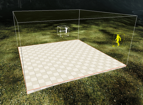
- Create a new Solid white box to mark the area covered by the proximity trigger. You may want to refer back to the White Boxing using Constructive Solid Geometry (CSG) section in Chapter 3, Playable levels in no time for the example on creating white box solids.
- Match the dimensions of the newly created Solid to that of the proximity trigger, except for the height. You will end up with a simple square on the ground measuring 10 x 10 x 1 meter, as in the following screenshot:
Now that we have our trigger set up in front of the SpawnPoint, let's use the trigger to kick off a scripted event using Flow Graph!
- Right-click on the Proximity Trigger entity and select the Create Flow Graph option.
- Next, add the Proximity Trigger as an entity node to the Flow Graph. As mentioned in the previous example, you can do this by selecting the Proximity Trigger entity and right-clicking in the graph and choosing Add Selected Entity.
- The second node that we will use is the HUD:DisplayTimedDebugMessage component node. This component node's function is straightforward; it outputs the text directly to screen based on its inputs.
- Add another component node to the graph called String:SetString. For this example, we will need three of these nodes.
- In two of the String:SetString nodes, type in the inputs. Click on the In port and type Entered into one and Exited into the other.
- Finally, add a Logic:Any node and hook up the links.
- Add the third and final set string node and link it to the output of the Logic:Any node, as seen in the following screenshot:

- To test this graph, switch to game mode and walk into the area where we placed the Proximity Trigger entity earlier. You will know it's functioning properly when you observe the text in the top right-hand side of the screen, which will display Entered when you enter the trigger and Exited when you leave the trigger volume.
To break down the actual logic here, the functions of each of the nodes need to be explained. This Flow Graph begins when the Proximity Trigger node is Entered in or Exited by the player. When the Enter or Leave output is triggered, this then sets the String:SetString node. The String:SetString node operates in a way that, when the input Set is triggered, it sends the In string value to the Out port. Since we have hooked up the Enter output of the Proximity Trigger node to the String:SetString node that has the string Entered typed in it, this will then send the string Entered to the Logic:Any node. Once the Logic:Any node receives the input, it then outputs the string on its output. We then use this signal to set the string in the last String:SetString node and also trigger the Set input of the node. Finally, the string is fed into the Message and Trigger input of the HUD:DisplayTimedDebugMessage node to display what exactly was triggered from the Proximity Trigger, either Entered or Exited/Leave.
This example is meant to show how the output from a trigger can be used to trigger whichever other components or entity nodes you like. It also demonstrates how you can take advantage of the fact that a node will take any input and try to convert it to its required data type. We use this in the final link in the Flow Graph, where a string is used as a Trigger signal and as the data to be displayed. In this case, we simply output the events to screen text rather than triggering something else in our game world, as this is the next step in our examples.
- What are the two methods most commonly used when scripting in the CryENGINE 3?
- Character editor and animation graph
- Track view and database view
- C++ and C#
- Lua and Flow Graph
- There are two principal types of flow nodes. What are they?
- Smart objects and character nodes
- Component and entity nodes
- Image nodes and game nodes
- Engine nodes and level nodes
- What specific flow node is used to set a key press in Flow Graph?
- Controller: Input node
- Debug: Keyboard node
- Input: Key node