
Electrode potentials, cells and corrosion
Publisher Summary
This chapter focuses on electrode potentials, cells, and corrosion. A metal is called half-cell when it comes in contact with a solution of its ions, and the potential difference of the half-cell is called the electrode potential of the half-cell. The symbol denoting the electrode potential is E, and the quantity is measured in volts. The electrode potential of a half-cell cannot be determined independently, but is measured by placing it in series with a different half-cell. These are joined together by a salt bridge, and a voltmeter is connected across the complete circuit to measure the voltage produced. A battery is a combination of more than one cell. The cells in a battery may be connected in series or in parallel. There are two main types of cell, namely, primary cells and secondary cells. When two different metals are joined together in a conducting solution, a simple cell is set up. In this simple cell, the metal highest in the electrochemical series is the anode and undergoes the decomposition reaction. This change of solid metal into dissolved metal is known as corrosion.
1. When a metal is immersed in a solution of its most stable ions, there are two possible reactions which may occur. These are: (a) the metal ions may leave the surface of the metal lattice and go into solution, resulting in the development of a negative charge on the metal surface (see Figure 8.1(a)), or (b) the metal ions from the solution may be deposited on the metal surface, resulting in the development of a positive charge on the metal surface (see Figure 8.1(b)). Both (a) and (b) result in a potential difference existing between the metal and the solution.
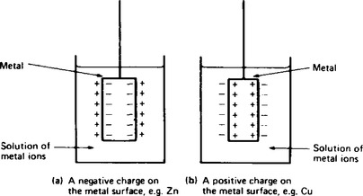
2. The reactions can be expressed by the general equation
where M is any metal and n is the oxidation state of the metal ion When equilibrium is displaced on the right, the reaction corresponds to reaction (a) described in para 1. Displacement of the reaction to the left corresponds to reaction (b) described in para 1.
3. Any metal in contact with a solution of its ions is called a half-cell, and the potential difference of the half-cell is called the electrode potential of the half-cell. The symbol denoting the electrode potential is E, and the quantity is measured in volts.
4. The electrode potential of a half-cell cannot be determined independently, but is measured by placing it in series with a different half-cell. These are joined together by a salt bridge, and a voltmeter is connected across the complete circuit to measure the voltage produced.
5. The electrode potential of a half-cell is dependent on three factors. These are:
(a) the concentration of the solution of the ions;
Because of this dependence, a set of standard conditions have been selected for use in the measurement of electrode potentials. These are:
When measured under these conditions the values become standard electrode potentials and are given the symbol E![]() , the units of which are also in volts.
, the units of which are also in volts.
6. Since the electrode potentials of half-cells can only be determined when placed in series with a known potential half-cell, a standard electrode has been selected for this purpose. The standard reference electrode is the standard hydrogen electrode which is shown in Figure 8.2.
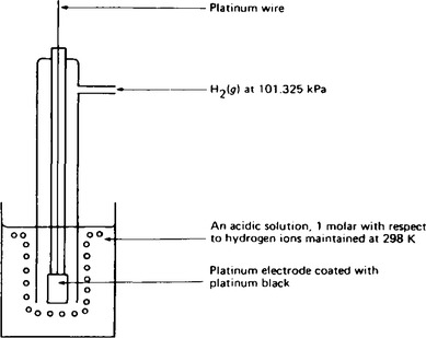
The electrode consists of a piece of platinum foil coated with platinum black embedded in the walls of a glass tube. This foil is connected by means of a platinum wire to the external lead. The platinum black material is very finely divided platinum and it catalyses the reaction which occurs between hydrogen gas and hydrogen ions as shown in the equation
The hydrogen gas is bubbled through the electrode at a pressure of 101.325 kPa, and the concentration of the acid solution must be exactly 1.00 molar strength with respect to hydrogen ions.
During experimental work to determine standard electrode potentials, the acid solution must be thermostatically controlled at 298 K. By mixing together the hydrogen gas and the hydrogen ions in the presence of the platinum electrode, the electrode potential is developed between the element (hydrogen), and a solution of its ions (hydrogen ions). When the electrode is set up in this way, the standard electrode potential which is developed is defined as zero.
7. The standard hydrogen electrode requires considerable time and care to set up, and it is difficult to move from one experiment to another. Consequently, alternative reference electrodes have been devised, an example being the calomel reference electrode which is shown in Figure 8.3.
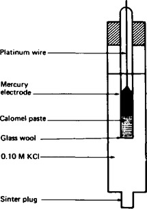
In this standard electrode, the platinum electrode provides the contact between the mercury and the calomel paste, which contains mercury (I) chloride, Hg2Cl2 as the source of Hg+ ions. The concentration of the mercury (I) chloride is maintained by placing it in contact with 0.1 molar potassium chloride solution. The electrode potential of this electrode, with respect to the standard hydrogen electrode, is + 0.336 V. Thus when the standard calomel electrode is used, + 0.336 V must be added to any standard electrode potential which is measured.
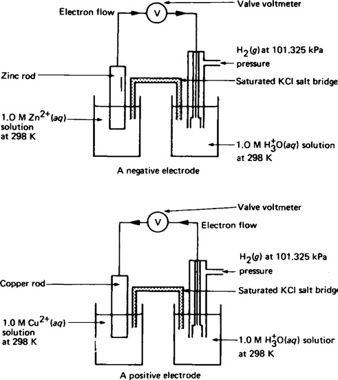
8. When the standard hydrogen electrode is connected in series to another standard half-cell as shown in Figure 8.4 the direction of the current flow is dependent on the particular metal/metal ion electrode system which is used. The convention which has been adopted is that, metals which release hydrogen gas from a solution of hydrogen ions are designated as negative (– ve) with respect to the standard electrode. Metals which do not release hydrogen gas are designated as positive (+ ve) with respect to the standard electrode. Examples of some E![]() values are shown in Table 7.1, page 44.
values are shown in Table 7.1, page 44.
9. When two different standard half-cells are connected in series in a circuit, they form a galvanic cell as shown in Figure 8.5. The resultant potential difference of the two standard half-cells is called the standard electromotive force of the galvanic cell, and is symbolised by E![]() cell.
cell.
10. A galvanic cell can be represented systematically in the form of a cell equation. Any two half-cells can be represented by Ax +| A and By+ | B which when forming a galvanic cell can be represented by the cell equation
In this equation the solid vertical line represents the solid electrodes and the dotted line represents the salt bridge joining the half-cells together. The standard e.m.f. of the cell is defined as:
The standard e.m.f. of the cell E![]() cell = E
cell = E![]() (Right Hand Electrode) – E
(Right Hand Electrode) – E![]() (Left Hand Electrode), which is simplified to:
(Left Hand Electrode), which is simplified to:
For the general cell equation given above, A| Ax+ is the left hand electrode, and By+ | B is the right hand electrode. The polarity of the right hand electrode is defined as being the same sign as the e.m.f. of the galvanic cell, i.e. if the E![]() cell value is positive, then the right hand electrode has positive polarity. For example, when the zinc half-cell and the hydrogen half-cell are connected together to form a galvanic cell as shown in Figure 8.4 the cell equation is written as
cell value is positive, then the right hand electrode has positive polarity. For example, when the zinc half-cell and the hydrogen half-cell are connected together to form a galvanic cell as shown in Figure 8.4 the cell equation is written as
where LHE and RHE signify the left hand electrode and the right hand electrode respectively. The e.m.f of this cell is calculated using the equation
and by substituting the electrode potential values gives
This means that for this galvanic cell, the e.m.f. is +0.76 V, the hydrogen electrode is the positive electrode and the zinc electrode is the negative electrode. Similarly, for the copper electrode and hydrogen electrode the cell equation is
This means that for this galvanic cell, the cell e.m.f. is −0.34 V, the hydrogen electrode is negative and the copper electrode is positive.
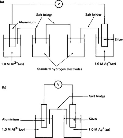
11. When the standard half-cells of aluminium and silver are combined into a galvanic cell using hydrogen electrodes as shown in Figure 8.5(a). The cell equation for this arrangement is
From Table 7.1 the E![]() values for the aluminium and silver are −1.67 V and +0.80 V respectively. The circuit in Figure 8.5(a) is a combination of the two galvanic cells in series which can be represented by the cell equations
values for the aluminium and silver are −1.67 V and +0.80 V respectively. The circuit in Figure 8.5(a) is a combination of the two galvanic cells in series which can be represented by the cell equations
The total e.m.f. of the two galvanic cells in series is given by
The e.m.f. produced is + 2.47 V.
Similarly, the cell equation for the circuit shown in (b) is
The e.m.f of the cell is +2.47 V.
From the results it can be seen that when a galvanic cell is formed by two half-cells, it is unnecessary to consider the standard hydrogen electrodes when calculating values of e.m.f. It should be noted that when drawing a diagram of the circuit or writing a cell equation for a galvanic cell, it is usual by convention to select the more positive electrode as the right hand electrode.
12 The list of values of standard electrode potentials shown in Table 7.1 with the most negative at the top, is also called the electrochemical series. In the table, any element above another can theoretically be used to displace the lower element from a solution of its ions. For example, magnesium is above zinc in the table and the theoretical reaction is
Similarly, zinc is above copper and the equation of reaction is
Such reactions, where a metal is deposited from its solution by another metal are called displacement reactions.
13. A displacement reaction can be considered as two reactions taking place simultaneously. For the magnesium and zinc reaction shown above the reactions taking place are
Reaction (a) involves a loss of electrons by magnesium and this process is called oxidation. Reaction (b) involves a gain in electrons by zinc ions and this process is called reduction. The reactions can be called oxidation/reduction reactions or more commonly redox reactions, where red- is taken from reduction and -ox from oxidation. It is Important to remember that a reduction can only take place accompanied by an oxidation, and vice versa.
14. When a galvanic cell is formed the positive electrode undergoes reduction (gaining electrons), whilst the negative electrode undergoes oxidation (losing electrons). Since the reaction at the positive electrode involves the attraction of positively charged ions, or cations, the electrode is called the cathode. The other electrode undergoing electron loss is called the anode.
15. Applications of galvanic cells The production of an e.m.f. by chemical change offers a form of portable electricity. The production of electricity in amounts suitable for domestic and commercial purposes is achieved by arranging a series of cells into a battery. The simple cell shown in Figure 8.6 has two faults (a) polarisation effects and (b) local action effects.
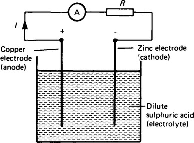
(a) If the simple cell shown in Figure 8.6 is left connected for some time, the current I decreases fairly rapidly. This is because of the formation of a film of hydrogen bubbles on the copper anode. This effect is known as the polarization of the cell. The hydrogen prevents full contact between the copper electrode and the electrolyte and this increases the internal resistance of the cell. The effect can be overcome by using a chemical depolarizing agent or depolarizer, such as potassium dichromate which removes the hydrogen bubbles as they form. This allows the cell to deliver a steady current.
(b) When commercial zinc is plated in dilute sulphuric acid, hydrogen gas is liberated from it and the zinc dissolves.
The reason for this is that impurities, such as traces of iron, are present in the zinc which set up small primary cells with the zinc. These small cells are short-circuited by the electrolyte, with the result that localized currents flow causing corrosion. This action is known as local action of the cell. This may be prevented by rubbing a small amount of mercury on the zinc surface, which forms a protective layer on the surface of the electrode.
16. When a galvanic cell is set up, the p.d. between its terminals when not connected to a load is the electromotive force of the cell. The e.m.f of a cell is measured by using a high resistance voltmeter connected in parallel with the cell. The voltmeter must have a high resistance otherwise it will pass current and the cell will not be on no-load. For example, if the resistance of a cell is 1 Ω and that of a voltmeter is 1 MΩ then the equivalent resistance of the circuit is 1 MΩ+ 1 Ω, i.e. approximately 1 MΩ, hence no current flows and the cell is not loaded.
17. The voltage available at the terminals of a cell falls when a load is connected. This is caused by the internal resistance of the cell which is the opposition of the material of the cell to the flow of current. The internal resistance acts in series with other resistances in the circuit. Figure 8.7 shows a cell of e.m.f. E volts and internal resistance r, XY represents the terminals of the cell.
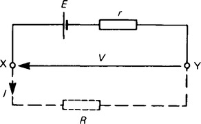
When a load (shown as resistance R) is not connected, no current flows and the terminal p.d., V = E. When R is connected a current I flows which causes a voltage drop in the cell, given by Ir. The p.d. available at the cell terminals is less than the e.m.f. of the cell and is given by V = E – Ir. Thus if a battery of e.m.f. 12 V and internal resiatance 0.01 Ω delivers a current of 100 A, the terminal p.d.,
When a current is flowing in the direction shown in Figure 30.7 the cell is said to be discharging (E> V), and when a current flows in the opposite direction to that shown in Figure 8.7 the cell is said to be charging (V < E).
18. A battery is a combination of more than one cell. The cells in a battery may be connected in series or in parallel.
(i) For cells connected in series:
Total e.m.f. = sum of cell’s e.m.f.’s
Total internal resistance = sum of cell’s internal resistances.
(ii) For cells connected in parallel:
If each cell has the same e.m.f. and internal resistance:
Total e.m.f. = e.m.f. of one cell.
Total internal resistance of n cells = ![]() × internal resistance of one cell.
× internal resistance of one cell.
19. There are two main types of cell – primary cells and secondary cells.
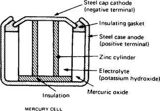
(i) Primary cells cannot be recharged, that is, the conversion of chemical energy is irreversible and the cell cannot be used once the chemicals are exhausted. Examples of primary cells include the Leclanché cell and the mercury cell. A typical dry Leclanché cell is shown in Figure 8.8. Such a cell has an e.m.f. of about 1.5 V when new, but this falls rapidly if in continuous use due to polarisation. The hydrogen film on the carbon electrode forms faster than can be dissipated by the depolariser.
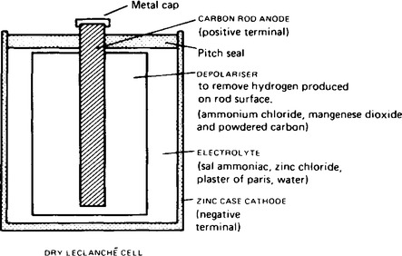
The Leclanché cell is suitable only for intermittent use, applications including torches, transistor radios, bells, indicator circuits, gas lighters, controlled switchgear and so on. The cell is the most commonly used of primary cells, is cheap, requires little maintenance and has a shelf life of about two years. A typical mercury cell is shown in Figure 8.9. Such a cell has an e.m.f. of about 1.3 V which remains constant for a relatively long time. Its main advantages over the Leclanché cell is its smaller size and its long shelf life. Typical practical applications include hearing aids, medical electronics and for guided-missiles.
(ii) Secondary cells can be recharged after use, that is, the conversion of chemical energy to electrical energy is reversible and the cell may be used many times. Examples of secondary cells include the lead-acid cell and alkaline cells.
A typical lead-acid cell is constructed of:
(i) A container made of glass, ebonite or plastic;
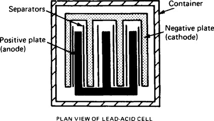
(ii) Lead plates. The negative plate (cathode) consists of spongy lead and (b) the positive plate (anode) is formed by pressing lead peroxide into the lead grid. The plates are interleaved as shown in the plan view of Figure 8.10 to increase their effective cross-sectional area and to minimise internal resistance;
(iii) Separators made of glass, celluloid or wood;
(iv) An electrolyte which is a mixture of sulphuric acid and distilled water. The relative density (or specific gravity) of a lead-acid cell, which may be measured using a hydrometer, varies between about 1.26 when the cell is fully charged to about 1.19 when discharged. The terminal p.d. of a lead-acid cell is about 2 V. When a cell supplies current to a load it is said to be discharging. During discharge:
(i) The lead peroxide (positive plate) and the spongy lead (negative plate) are converted into lead sulphate, and
(ii) The oxygen in the lead peroxide combines with hydrogen in the electrolyte to form water. The electrolyte is therefore weakened and the relative density falls. The terminal p.d. of a lead-acid cell when fully discharged is about 1.8 V.
A cell is charged by connecting a d.c. supply to its terminals, the positive terminal of the cell being connected to the positive terminal of the supply. The charging current flows in the reverse direction to the discharge current and the chemical action is reversed. During charging:
(i) The lead sulphate on the positive and negative plates is converted back to lead peroxide and lead respectively, and
(ii) The water content of the electrolyte decreases as the oxygen released from the electrolyte combines with the lead of the positive plate. The relative density of the electrolyte thus increases.
The colour of the positive plate when fully charged is dark brown and when discharged is light brown. The colour of the negative plate when fully charged is grey and when discharged is light grey. Practical applications of such cells include car batteries, telephone circuits and for traction purposes — such as milk delivery vans and fork lift trucks.
There are two main types of alkaline cell the nickel-iron cell and the nickel-cadmium cell. In both types the positive plate is made of nickel hydroxide enclosed in finely perforated steel tubes, the resistance being reduced by the addition of pure nickel or graphite. The tubes are assembled into nickel-steel plates.
In the nickel-iron cell, (sometimes called the Edison cell or nife cell), the negative plate is made of iron oxide, with the resistance being reduced by a little mercuric oxide, the whole being enclosed in perforated steel tubes and assembled in steel plates. In the nickel-cadmium cell the negative plate is made of cadmium. The electrolyte in each type of cell is a solution of potassium hydroxide which does not undergo any chemical change and thus the quantity can be reduced to a minimum. The plates are separated by insulating rods and assembled in steel containers which are then enclosed in a non-metallic crate to insulate the cells from one another. The average discharge p.d. of an alkaline cell is about 1.2 V.
Advantages of an alkaline cell (for example, a nickel-cadmium cell or a nickel-iron cell) over a lead-acid cell include:
(ii) capable of withstanding heavy charging and discharging currents without damage;
(iv) for a given capacity is lighter in weight;
(v) can be left indefinitely in any state of charge or discharge without damage;
Disadvantages of an alkaline cell over a lead-acid cell include:
(i) is relatively more expensive;
(ii) requires more cells for a given e.m.f.;
Alkaline cells may be used in extremes of temperature and also in conditions where vibration is experienced or where duties require long idle periods or heavy discharge currents. Practical examples include traction and marine work, lighting in railway carriages, military portable radios and for starting diesel and petrol engines. However, the lead-acid cell is the most common one in practical use.
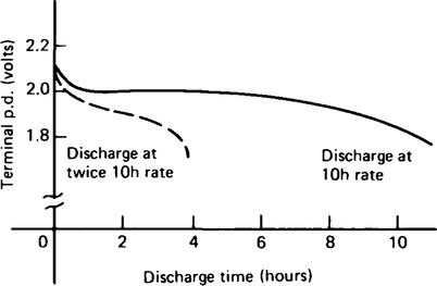
20. The capacity of a cell is measured in ampere-hours (Ah). A fully charged 50 Ah battery rated for 10 h discharge at a steady current of 5 A for 10 h, but if the load current is increased to 10 A, then the battery is discharged in 3–4 h, since the higher the discharge current, the lower is the effective capacity of the battery. Typical discharge characteristics for a lead-acid cell are shown in Figure 8.11.
Corrosion of metals
21. When two different metals are joined together in a conducting solution, a simple cell is set up. In this simple cell, the metal highest in the electrochemical series is the anode and undergoes the decomposition reaction
This change of solid metal into dissolved metal is called corrosion.
22. The metals used in everyday life come into contact with rain water on land, sea water at sea and oxygen from the atmosphere. Rain water contains dissolved carbon dioxide according to the equation
and in industrial areas dissolve oxides of sulphur
which means that rain water can act as an electrolyte even though it is a poor conductor. Sea water contains sodium chloride and is a good conductor of electricity. Metals in contact with these solutions in the presence of oxygen form corrosion products. For example, copper forms a protective layer of basic copper carbonate which is green in colour preventing further corrosion, similarly aluminium forms a surface layer of aluminium oxide and lead also forms a protective layer. These protective layers are effective because they are insoluble in water. However when iron or steel is corroded, the iron (III) oxide formed is water soluble to some extent and is granular and porous offering a continuous supply of metal to be reacted. This process is called the rusting of iron and is a major problem in domestic and commercial uses.
23 The rusting of iron Iron and steel are used extensively for purposes needing strong incompressible structures. It is a readily available material extracted from its ores by reduction with coke, a simplified equation being:
The production of iron and steel goods by forging, casting and other forms of machining, results in regions of different stress in the product. Additionally small amounts of impurities are present in the surface. When these areas of stress or impurity are exposed to moisture and oxygen, rusting occurs. The nail shown in Figure 8.12 has anodic regions near the head and tip, both being regions of different stress originated during production.
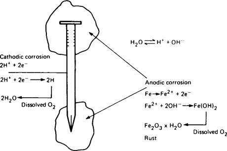
The simplified equations of corrosion in anodic and cathodic regions are also shown in Figure 8.12. Eventually the head and tip will become highly corroded. A further point of interest in the rusting process is that once it begins in a particular region, it continues at that point. The problem industry faces is that this type of rusting will eventually pass completely through the iron forming holes and thus a serious weakening of the structure. The process is called ‘pitting’. The composition of rust is variable and is usually represented by the formula Fe2O3.xH2O where x is the variable quantity.
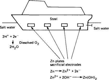
24. The prevention of rusting Any metal above iron in the electrochemical series and in contact with it will undergo corrosion in preference to iron. This fact is utilised in employing protective anodes attached to iron and steel surfaces. The hull of a ship can be protected in this way as shown diagrammatically in Figure 8.13. When the anode is completely dissolved new anodes can be used to replace them. The graphic term given to anodes used in this way is ‘sacrificial electrodes’.
25. Other methods of protection Methods used to prevent or reduce the corrosion of metals utilise the exclusion of moisture and oxygen from the metal surface. Such methods include painting, immersion in oil, covering in grease, plastic coating, plating with non-corrosive metals like chrome, nickel or silver, dipping in other metals for example, galvanising and sheradising.