Single phase transformers
Publisher Summary
This chapter discusses the single phase transformation. A transformer is a device that uses the phenomenon of mutual induction to change the values of alternating voltages and currents. In fact, one of the main advantages of alternating current (a.c.) transmission and distribution is the ease with which an alternating voltage can be increased or decreased by transformers. Losses in transformers are generally low and, thus, efficiency is high. Being static, it has a long life and is reliable. Transformers range in size from the miniature units used in electronic applications to the large power transformers used in power stations. The principle of operation is the same for each. A transformer consists of two electrical circuits linked by a common ferromagnetic core. One coil is termed the primary winding that is connected to the supply of electricity, and the other the secondary winding that can be connected to a load.
1. Mutual inductance, M, is the property whereby an e.m.f. is induced in a circuit by a change of flux due to current changing in an adjacent circuit.
(i) A transformer is a device which uses the phenomenon of mutual induction to change the values of alternating voltages and currents. In fact, one of the main advantages of a.c. transmission and distribution is the ease with which an alternating voltage can be increased or decreased by transformers.
(ii) Losses in transformers are generally low and thus efficiency is high. Being static they have a long life and are very reliable.
(iii) Transformers range in size from the miniature units used in electronic applications to the large power transformers used in power stations. The principle of operation is the same for each.
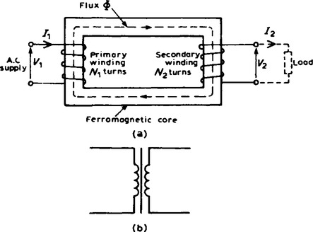
3. A transformer is represented in Figure 20.1(a) as consisting of two electrical circuits linked by a common ferromagnetic core. One coil is termed the primary winding which is connected to the supply of electricity, and the other the secondary winding, which may be connected to a load. A circuit diagram symbol for a transformer is shown in Figure 20.1(b).
Transformer principle of operation
(i) When the secondary is an open-circuit and an alternating voltage V1 is applied to the primary winding, a small current — called the no-load current I0 — flows, which sets up a magnetic flux in the core. This alternating flux links with both primary and secondary coils and induces in them emfs of E1 and E2 volts respectively by mutual induction.
(ii) The induced e.m.f. E in a coil of N turns is given by E = N (ΔΦ)/t volts, where ((ΔΦ/t) is the rate of change of flux. In an ideal transformer, the rate of change of flux is the same for both primary and secondary and thus E1/N1 = E2/N2, i.e. the induced e.m.f. per turn is constant.
Assuming no losses, E1 = V1 and E2 = V2.
(iii) V1/V2 is called the voltage ratio and N1/N2 the turns ratio, or the ’transformation ratio’ of the transformer.
If N2 is less than N1 then V2 is less than V1 and the device is termed a step-down transformer.
If N2 is greater than N1, then V2 is greater than V1 and the device is termed a step-up transformer.
(iv) When a load is connected across the secondary winding, a current I2 flows. In an ideal transformer losses are neglected and a transformer is considered to be 100% efficient. Hence
i.e. V1I1 cos ϕ1 = V2I2 cos ϕ2
However the primary and secondary power factors (i.e. cos ϕ1 and cos ϕ2) are nearly equal at full load. Hence, V1 = V2 I2, i.e. in an ideal transformer, the primary and secondary ampere-turns are equal.
Combining equations (1) and (2) gives:
5. The rating of a transformer is stated in terms of the voltamperes that it can transform without overheating. With reference to Figure 20.1(a), the transformer rating is either V1I1 or V2 I2, where I2 is the full-load secondary current.
6. There are broadly two sources of losses in transformers on load-copper losses and iron losses.
(a) Copper losses are variable and result in a heating of the conductors, due to the fact that they possess resistance. If R1 and R2 are the primary and secondary winding resistances then the total copper loss is I21R1 + I22 R2.
(b) Iron losses are constant for a given value of frequency and flux density and are of two types — hysteresis loss and eddy current loss.
(i) Hysteresis loss is the heating of the core as a result of the internal molecular structure reversals which occur as the magnetic flux alternates. The loss is proportional to the area of the hysteresis loop and thus low loss nickel iron alloys are used for the core since their hysteresis Mops have small areas.
(ii) Eddy current loss is the heating of the core due to e.m.f.’s being induced not only in the transformer windings but also in the core. These induced e.m.f.’s set up circulating currents, called eddy currents. Owing to the low resistance of the core eddy currents can be quite considerable and can cause a large power loss and excessive heating of the core. Eddy current losses can be reduced by increasing the resistivity of the core material or, more usually, by laminating the core (i.e. splitting it into layers or leaves) when very thin layers of insulating material can be inserted between each pair of laminations. This increases the resistance of the eddy current path, and reduces the value of the eddy current.
and is usually expressed as a percentage. It is not uncommon for power transformers to have efficiencies of between 95% and 98%. The output power V2I2 cos ϕ2, the losses = copper loss + iron losses, and the input power = output power + losses.
Transformer no-load phasor diagram
(i) The core flux is common to both primary and secondary windings in a transformer and is thus taken as the reference phasor in a phasor diagram. On no-load the primary winding takes a small no-load current I0 and since, with losses neglected, the primary winding is a pure inductor, this current lags the applied voltage V1 by 90°. In the phasor diagram assuming no losses, shown in Figure 20.2(a), current I0, produces the flux and is drawn in phase with the flux. The primary induced e.m.f. E1 is in phase opposition to V1 (by Lenz’s law) and is shown 180° out of phase with V1 and equal in magnitude. The secondary induced e.m.f. is shown for a 2 : 1 turns ratio transformer.
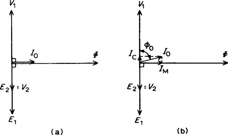
(ii) A no-load phasor diagram for a practical transformer is shown in Figure 20.2(b). If current flows then losses will occur. When losses are considered then the no-load current I0, is the phasor sum of two components — (i) IM, the magnetising component, in phase with the flux, and (ii) Ic the core loss component (supplying the hysteresis and eddy current losses). From Figure 20.2(b):
Transformer construction
(i) There are broadly two types of transformer construction — the core type and the shell type, as shown in Figure 20.3. The low and high voltage windings are wound as shown to reduce leakage flux.
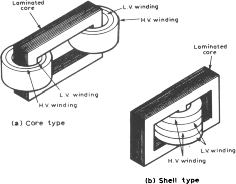
(ii) For power transformers, rated possibly at several MVA and operating at a frequency of 50 Hz in Great Britain, the core material used is usually laminated silicon steel or stalloy, the laminations reducing eddy currents and the silicon steel keeping hysteresis loss to a minimum.
(iii) For audio-frequency (a.f.) transformers, rated from a few mVA to no more than 20 VA, and operating at frequencies up to about 15 kHz, the small core is also made of laminated silicon steel.
(iv) Radio-frequency (r.f.) transformers, operating in the MHz frequency region have either an air core, a ferrite core or a dust core. Ferrite is a ceramic material having magnetic properties similar to silicon steel, but having a high resistivity. Dust cores consist of fine particles of carbonyl iron or permalloy (i.e. nickel and iron), each particle of which is insulated from its neighbour. (v) Transformer windings are usually of enamel-insulated copper or aluminium.
(vi) Cooling is achieved by air in small transformers and oil in large transformers.
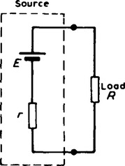
’The power transferred from a supply source to a load is at its maximum when the resistance of the load is equal to the internal resistance of the source’.
In Figure 20.4, when r = R, the power transferred from the source to the load is a maximum.
11. A method of achieving maximum power transfer between a source and a load is to adjust the value of the load resistance to ’match’ the source internal resistance. A transformer may be used as a resistance matching device by connecting it between the load and the source. The reason why a transformer can be used for this is shown below. With reference to Figure 20.5:

For an ideal transformer, V1 = (N1/N2) V2 and I1 = (N2/N1)I2 from equation (3)). Thus the equivalent input resistance R1 of the transformer is given by:
Hence by varying the value of the turns ratio, the equivalent input resistance of a transformer can be ’matched’ to the internal resistance of a load to achieve power transfer.
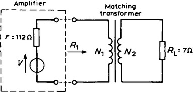
For example, the output stage of an amplifier has an output resistance of 112 Ω The optimum turns ratio of a transformer which would match a load resistance of 7Ω to the output resistance of the amplifier is obtained as follows:
The equivalent input resistance R1 of the transformer needs to be 112Ω for maximum power transfer. The circuit diagram is shown in Figure 20.6.