
Chemical bonding in compounds
Publisher Summary
This chapter focuses on the chemical bonding in compounds. When two different elements combine together to form a chemical compound the bonding among the elements can be classified into four main types, namely, ionic bonding, covalent bonding, dative covalent bonding, and intermolecular bonding. Ionic bonds are permanent electrostatic forces of attraction formed between positively charged metallic ions and negatively charged nonmetallic ions. Compounds that are covalently bonded can be gases, liquids, or solids. The molecules that constitute these states have specific shapes that are dependent on the electronic repulsion forces within the molecule. As each bond contains a pair of electrons and because like charges repel each other, the bonds will be distributed to minimize the repulsion forces in the molecule. The majority of covalently bonded molecules are much more volatile than ionic compounds. This is because the forces of attraction among the molecules are weak intermolecular forces.
1. When two different elements combine together to form a chemical compound the bonding between the elements can be classified into four main types. These are
(a) ionic bonding which only occurs between metals and non-metals.
(b) covalent bonding which occurs between different non-metals or non-metals and elements of intermediate metallic/non-metallic character (e.g. aluminium),
(c) dative covalent bonding which occurs between particular molecules and in the formation of transition metal complexes, and
(d) intermolecular bonding which occurs between molecules which are already covalently bonded.
2. Ionic bonds are permanent electrostatic forces of attraction formed between positively charged metallic ions and negatively charged non-metallic ions.
3. Metal atoms lose electrons to attain a stable electronic structure identical to that of a noble gas. For example, sodium atoms have the electronic structure 2 · 8 · 1, and by losing one electron becomes the sodium ion, Na+ with an electronic structure of 2 · 8, the same as neon. The number of electrons lost by a metal atom is the number required to attain a noble gas structure and is usually 1, 2 or 3. Positive ions are called cations and are assigned positive because the structure will have an excess of protons. Some examples of positive ions are shown in Figure 57.1.

4. Non-metallic atoms gain electrons to form negative ions, called anions. The number of electrons gained is that number which will give the negative ion a stable structure. For example, oxygen has the structure 2 · 6 and by gaining 2 electrons the oxide ion is formed with the electronic structure 2 · 8, the same as neon. Other examples are given in Figure 57.1.
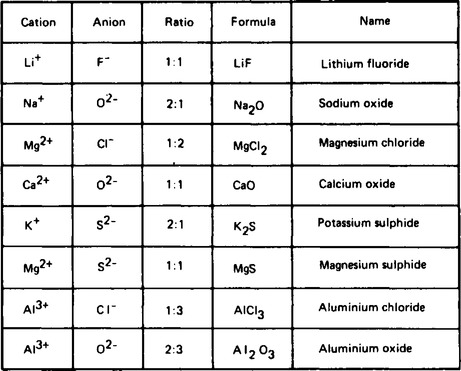
5. The combination of cations (positive) and anions (negative) into compounds, must be in a ratio which will be electrically neutral. For example, calcium forms Ca+2 ions and chlorine forms Cl−1 ions, and in order that calcium chlorine shall be neutral the ratio of cations to anions must be 1:2, i.e. Ca+2 : 2Cl−1 and the formula is represented as CaCl2. Other examples of compound formation are given in Figure 57.2.
6. In the solid state, the external appearance of ionic compounds shows clearly that different crystal shapes are possible for different compounds. The external shape of the crystal does not give any information about the internal structure of the crystal lattice.
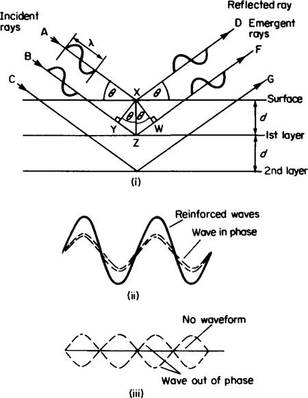
7. The composition of inorganic solids has been shown by X-ray crystallographic methods devised by Sir William Bragg and his son Sir William L. Bragg to exist in regular arrangements of particles. They showed that the diffraction of light through a diffraction grating produces a series of bands of intensified light interspersed with bands of darkness. This was interpreted using the wave theory of light, as the reinforcement of two waves in phase (see Figure 57.3(ii)), to explain the intensified bands, and the cancellation of light as a result of two wave forms out of phase (see Figure 57.3(iii)).
The ability of a diffraction grating to produce diffraction patterns depends on the wavelength of the type of light used. Since visible light is one type of electromagnetic radiation, other forms of radiation should be capable of diffraction if a suitable diffraction grating can be found.
Sir William Bragg and his son discovered that crystal lattices were able to form diffraction patterns using X-rays. The existence of diffraction patterns was very good evidence in support of the theory that in solid state the particles are arranged in a regular pattern which could be resolved into layers depending on the way in which the crystal lattice is viewed.
If a set of planes are considered as shown in Figure 57.3(i), the wave labelled AXD which is incident onto the surface of the crystal at an angle θ, strikes the surface particle at X and is reflected at an angle of θ. The second wave BZF meets the surface at a position where no particle is present and passes through the lattice structure until it strikes a particle at Z and is diffracted back through the crystal lattice surface. The waves are in phase when they are incident to the lattice surface but the wave BZF must travel a longer path than the wave AXD. For the emergent waves to be in phase, the extra distance travelled by the wave BSF must be equal to a whole number of wavelengths. Bragg found that by varying the incident angle θ, regions of intense radiation could be detected, followed by regions where no radiation could be detected. For a fixed wavelength of X-radiation, λ, Bragg related the extra distance travelled by the second wave as:
This equation is called the Bragg equation and for varying values of n and θ the interplanar distance d can be found. A knowledge of these interplanar distances correspond to the distance between ions or atoms (single or in groups) and the lattice crystal can be discovered by constructing models of them.
9 The application of the Bragg equation can be made using the following data. When a crystal of sodium chloride is held in a certain orientation and X-radiation of wavelength 0.0597 nm is allowed to fall upon it, regions of radiation can be detected when angle of incident radiation is 12.25° and 25.1°. To find the interplanar distance use must be made of the theory that in order that a region of radiation is detected, the Bragg equation must be obeyed. The equation is
where d is the interplanar distance, θ is the angle of incidence n is an integer and λ is the wavelength.
Assuming n = 1, and using θ = 12.25° and λ = 0.0597 nm and substituting these values into the equation gives
Rearranging this expression gives
Hence the interplanar distance is 0.1407 nm.
For the second value of θ = 25.1°, the substitution of the appropriate values into the Bragg equation assuming that n = 2 gives
Rearranging this expression gives
Again the interplanar distance is 0.1407 nm.
Using this interplanar distance together with values found using different orientations of the sodium chloride crystal allow a model to be constructed to represent the solid structure.
9. The structures of the ionic solids can be simply classified into the types AB and AR2 where A is the metal ion and B is the non-metal ion.
10. Ionic solids of the type AB can be sub-divided again into two main types, the sodium chloride oe rock salt structure and the caesium chloride structure. These are the lattice structures of the group 1 halides which are shown in Figure 57.4(a) and (b) and examples of which are given in Table 57.1.
Table 57.1
The crystal structure of some ionic solids
| Lattice type | Examples | |
| Sodium chloride or Rock-salt structure 6,6 co-ordination | Lif NaF KF LiCl NaCl KCl RbCl LiBr NaBr KBr RbBr Lil NaI KI RbI NH4I | MgO CaO SrO BaO MnO NiO |
| Caesium chloride structure 8,8 co-ordination | CsCl RbF NH4Cl CsBr NH4Br CsI | |
| Fluorite structure 8,4 co-ordination | CaF2 SiCl2 SrF2 CdF2 BaF2 PbF2 |

The other general formula for ionic solids, AB2 is represented by the fluorite structure of calcium fluoride shown in Figure 57.4(c).
11. The change in co-ordination numbers in these ionic lattice structures and their different arrangements can be explained by considering that the arrangement of the ions depends on three main properties, firstly the difference in charge, secondly the relative sizes of cations and anions and thirdly the ratio of cations to anions.
The arrangement of ions
12. Since cations are positively charged and anions are negatively charged, any crystal lattice will experience repulsive forces between identical cations and identical anions of identical charge, whereas, it will experience forces of attraction between oppositely charged cations and anions. The arrangement of ions must be such that electrical neutrality exists in the structure. This is achieved by a cation surrounding itself with anions, and by an anion surrounding itself with cations.
The radius ratio
(i) A simple application of this principle would lead to the same lattice structure for all ionic solids but the ability of cations and anions to pack together also depends on the relative sizes of these particles. Cations are much smaller than anions and it is easier to view the positioning of anions about a cation than vice versa. For example, by representing a simple arrangement of 4 anions around a central cation as shown in Figure 57.5 the ratio of the size of the cation to the size of the anion can be found by considering the triangle ABC. It is constructed as a right angled triangle in which CÂB= A![]() C= 45°.
C= 45°.

Using the identity, cos 45° = ![]() gives
gives
Rearranging this expression gives
Hence for this site the radius ratio for touching contact is 0.414.
By placing 2 more anions directly above and below the cation produces an octahedral site in which the cation is in contact with 6 anions.
(ii) For the solution chloride crystal lattice (Figure 57.4(a)), each Na+ ion has six Cl− ions as near neighbours. This is because the ionic radius of the sodium ion is small enough to fit into such a site within the lattice. The geometrical calculations show that for the six Cl− ions to touch the Na+ ions, the radius ratio,
Since the ionic radius of Na+ is 0.98 A and that of Cl− is 1.81 A then
This means that in sodium chloride the ions are not touching but are dispersed about the central Na+ ion.
(iii) As the radius ratio increases the positioning of a cation in such a site causes the anions to be moved farther and farther apart. This results in a change of site for the cation when the radius ratio reaches 0.732. This crystal lattice structure is shown by caesium chloride (Figure 57.4(b)), where instead of six near neighbours each Cs+ ion is surrounded by eight Cl− ions and each Cl− ion is surrounded by eight Cs+ ions. The ionic radii of Cs+ and Cl− are 1.65 A and 1.81 A giving a value of
The size of the radius ratio is responsible for a change in coordination number from 6:6 to 8:8. Hence the radius ratio for combinations of ions of equal charge can be used to predict the lattice structure of the compound. Some values of ionic radii together with limiting ratio values are given in Table 57.2.
Table 57.2
| Cation | Ionic radius (nm) | Cation | Ionic radius (nm) | radius Anion | Ionic (nm) |
| Li+ | 0.068 | Mg+2 | 0.065 | F- | 0.133 |
| Na+ | 0.098 | Ca+2 | 0.094 | Cl- | 0.181 |
| K+ | 0.133 | Sr+2 | 0.110 | Br− | 0.196 |
| Rb+ | 0.149 | Ba+2 | 0.134 | I− | 0.229 |
| Cs+ | 0.165 | Mn+2 | 0.080 | O−2 | 0.146 |
| NH+4 | 0.148 | Ni+2 | 0.072 | ||
| Cd+2 | 0.097 | ||||
| Pb+2 | 0.084 | ||||
| sodium chloride | 0.414 to 0.732 | ||||
| caesium chloride | 0.722 to 1. | ||||
| fluorite | 0.65 to 1. |

14. The arrangement of ions of different charges is represented here by the fluorite structure of calcium fluoride CaF2 in which each cation has a charge of + 2 and each anion − 1, and for electrical neutrality there must be twice as many anions as cations. The structure of this crystal lattice is such that each Ca2+ ion is surrounded by eight F− ions and each F− ion is surrounded by four Ca+ ions and this results in a coordination number of 8:4. Other examples are given in Tables 57.1 and 57.2.
15. When two different elements combine to form a compound which is not ionic, then the bonding between them is called covalent bonding. The number of covalent bonds formed by a non-metal is discussed in Chapter 56, para 5 for the elements. When different elements combine, the ratio is such that each element attains a stable electronic structure. For example, in methane, CH4, the carbon atom requires a share in four other electrons to attain stability, and hydrogen requires a share in one other electron. Some examples of compounds held together by covalent bonding are shown in Figure 57.6.

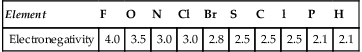
16. The major difference between covalent bonds in elements and those in compounds is that in the elements, the two electrons forming the covalent bond are equally shared between the two contributing atoms, but in compounds the sharing of electrons is unequal. This is because each element has a specific attracting power for other electrons in covalent bonds. This power is called electronegativity and the arbitrary values assigned to the principal non-metals are shown in Table 57.3.
When two different elements form a covalent bond there will be a difference in the electronegativity values of the two elements. The atom which has the higher electronegativity will attract the 2 electrons from one element to another and this is accompanied by the formation of partial electrical charges, positive at the lesser electronegative atom and negative at the greater electronegative atom. For example, hydrogen chloride, HCl, can be represeted as ![]() to show the two shared electrons one from each atom. Since chlorine is more electronegative than hydrogen a better representation is
to show the two shared electrons one from each atom. Since chlorine is more electronegative than hydrogen a better representation is ![]() .
.
In order to show the partial charges which are formed in the molecule the symbols δ+ and δ– are used, i.e. δ+H—Cδ−. This unequal sharing of electrons and the formation of polarised bonds has resulted in such molecules being called polar molecules. The factor which decides how polar a molecule becomes is the difference in the values of the electronegativities of the constituent elements.
17. Compounds which are covalently bonded can be gases, liquids or solids. The molecules which constitute these states have specific shapes which are dependent on the electronic repulsion forces within the molecule. Since each bond contains a pair of electrons and because like charges repel each other, the bonds will be distributed to minimise the repulsion forces in the molecule. The non-bonding pairs of electrons also give rise to repulsive forces. The shapes of some covalent compounds are given in Figure 57.7.

In addition to the shapes of the molecules the bond angles made between the atoms are dependent upon electronic effects. For example, the bonds angles in methane (H—C—H), ammonia (H—N—H) and water (H—O—H) are 109.5°, 107° and 104.5° respectively. These different bond angles can be explained by considering the dot and cross diagrams in Figure 57.6. This shows clearly that for methane there are four covalent bonds surrounding the carbon, each of which is composed of a bonding pair of electrons. The identical polarity of these bonding pairs leads to a repulsion between them.
In order to minimise these repulsive forces, bonds are distributed to the four corners of a regular tetrahedron. This results in each of the H—C—H bond angles being equal and 109.5° in magnitude, as shown in Figure 57.6. Similarly, dot and cross diagrams are also shown for ammonia and water in Figure 57.6. The difference between these compounds and methane are that (a), in ammonia, a non-bonding (lone pair) of electrons replaces one of the covalent bonds, and (b), in water two non-bonding pairs are present. The three covalent bonds around nitrogen, together with the non-bonding electron pair are distributed to the corners of an irregular tetrahedron to minimise repulsion forces.
However, since each of the three bond angles formed as H—N—H bonds are smaller than in methane, the repulsive force between the non-bonding pair and the bonding pairs must be slightly larger than the repulsive forces between the bonding pairs alone. This results in the smaller bond angle of 107°. Since the H—O—H bond angle is 104.5°, this is further evidence that the repulsive forces between non-bonding pairs are greater than those between a non-bonding pair and a bonding pair. This in turn is greater than the repulsion between two bonding pairs of electrons. 18 The majority of covalently bonded molecules are much more volatile than ionic compounds. This is because the forces of attraction between the molecules are weak intermolecular forces. These can be temporary dipole forces, permanent dipole forces or hydrogen bonds. Examples of these forces are shown in Figure 57.8.

It is the intensity of these intermolecular bonds which causes the covalently bonded substances to exist as liquids or solids.
19 Some metals combine with non-metals by covalent bonding to form a giant lattice structure, similar to ionic compounds, but with the elements present as atoms not ions. They can be subdivided into the types AB and AB2.
(i) Covalent solids of the type AB can be considered to be the zinc blende lattice structure and the wurzite lattice structure of the compound with the same formula ZnS. These structures are shown in Figures 57.9(a) and (b) and examples given in Table 57.4.
Table 57.4
The crystal structure of some covalent compounds
| Structure | Compound |
| Zinc blended structure 4,4 coordination | ZnS AgI CuBr HgS |
| Wurtzite struccture 4,4 co-ordination | ZnS NH4F ZnO |
| Rutile structure 6,3 co-ordination | TiO2 ZnF2 MnF2 CoF2 |
| SnO2 MnO2 | |
| β-Cristobalite structure 4,2 co-ordination | SiO2 Cu2O Ag2O |
| Cadmium iodide structure layer structure | CdI2 |

(ii) Covalent solids of the type AB2 can be classified into three types, the rutile or titanium dioxide structure, the β-eristobalite structure of SiO2 and the cadmium iodide layer structure. These are shown in Figures 57.9(c) to (e) with examples given in Table 57.4.
20. Covalent solids which exist as crystal lattice structures are equally as rigid as ionic crystals and have high melting and high boiling points. However, covalent solids are not conductors in the molten state and are not usually soluble in water.
21. The concept of co-ordination number is used to express the number of different nearest neighbours associated with an atom or ion. The number refers to the total number of near neighbours both in the same plane and above and below the particle under consideration.
The co-ordination numbers associated with the different lattice crystal structures are shown in Figure 57.9 and also in Table 57.4. For example, in the zinc blende structure shown in Figure 57.10, the zinc atoms are represented by • and the sulphur atoms by O. By considering a single zinc atom and the sulphur atoms nearest to it, it can be seen that four sulphur atoms are distributed tetrahedrally about the zinc atoms as shown diagrammatically in Figure 57.10(i). Similarly, four zinc atoms are distributed tetrahedrally about the sulphur atoms also shown in Figure 57.10(ii).
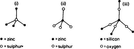
This means that both zinc and sulphur have four nearest neighbouring atoms and the co-ordination number of 4:4. Also in Figure 57.9(d) the silicon atoms in β-cristobalite are represented by • and the oxygen atoms by ![]() .
.
By considering a single silicon atom and the oxygen atoms surrounding it shown in Figure 57.10(iii), it can be seen that four oxygen atoms are distributed tetrahedrally about the silicon atom. Also included in Figure 57.10(iii) are the oxygen atoms which are shared linearly between two silicon atoms. Hence because each silicon atom has four atoms surrounding it and each oxygen atom is shared by two silicon atoms, the co-ordination number is 4:2.
22. Another type of covalent bonding that occurs between metals and non-metals and also between certain molecules is dative covalent bonding. Whereas in covalent bonds the two electrons which are shared come from different atoms, in dative bonding both electrons are given from one atom to another. The atom or group which gives both electrons is called the donor and the atom or molecule which accepts the electrons is called the acceptor molecule. Some examples of formation of dative bonds are given in Figure 57.11.

The two requirements necessary for dative bonding are that the donor molecule must have a non-bonding pair of electrons (lone pair), which it can donate and that the acceptor molecule must have a vacant ortital (be electron deficient), into which the electron pair can be accepted. Although these bonds are strong attractive bonds, they are not as strong as covalent bonds.
23 The properties of ionic and covalently bonded substances are summarised in Table 57.5.
Table 57.5
The properties of ionic and covalent compounds
| Property | Ionic | Covalent |
| State | Solid only | Solid, liquid gas |
| Melting point | High | Low |
| Boiling point | High | Low |
| Solubility in H2O | Good | Poor |
| Solubility in organic solvents | Poor | Good |
| Conductivity of molten solids | Good | Poor |
| Conductivity of aqueous solutions | Good | Poor |
| Reaction with water | Hydration | Hydrolysis |
| NaCl(s) + H2O = Na +(aq) + Cl− (aq) SiCl4 + 4H2O = Si(OH) + 4HCl |