Simply supported beams
Publisher Summary
This chapter focuses on simply supported beams. A beam is said to be in equilibrium when there is no tendency for it to move. There are two conditions for equilibrium, namely, the sum of the forces acting vertically downward must be equal to the sum of the forces acting vertically upward and the total moment of the forces acting on a beam must be zero. A simply supported beam is one that rests on two supports and is free to move horizontally. Typical practical applications of simply supported beams with point loadings include bridges, beams in buildings, and beds of machine tools. Although for equilibrium, the forces and moments cancel the magnitude and nature of these forces, and the moments are important as they determine both stresses and the beam curvature and deflection. Furthermore, the values of shearing force and bending moment will usually vary along a beam.
1. When using a spanner to tighten a nut, a force tends to turn the nut in a clockwise direction. This turning effect of a force is called the moment of a force or more briefly, just a moment. The size of the moment acting on the nut depends on two factors:
In general, with reference to Figure 36.1, the moment M of a force acting at a point P = force × perpendicular distance between the line of action of the force and P.
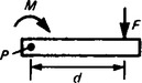
The unit of a moment is the newton metre (Nm). Thus, if force F in Figure 36.1 is 7 N and distance d is 3 m, then the moment at P is 7(N) × 3(m), i.e. 21 Nm.
2. If more than one force is acting on an object and the forces do not act at a point, then the turning effect of the forces, that is, the moment of the forces, must be considered.
Figure 36.2 shows a beam with its support (known as its pivot or fulcrum), at P, acting vertically upwards, and forces F1 and F2 acting vertically downwards at distances a and b respectively from the fulcrum.

A beam is said to be in equilibrium when there is no tendency for it to move.
There are two conditions for equilibrium:
(i) the sum of the forces acting vertically downwards must be equal to the sum of the forces acting vertically upwards, i.e. for Figure 36.2,
(ii) the total moment of the forces acting on a beam must be zero; for the total moment to be zero:
‘the sum of the clockwise moments about any point must be equal to the sum of the anticlockwise moments about that point’.
This statement is known as the principle of moments. Hence, taking moments about P in Figure 36.2, F2 × b = the clockwise moment, and F1 × a = the anticlockwise moment. Thus for equilibrium:
(i) A simply supported beam is one which rests on two supports and is free to move horizontally.
(ii) Two typical simply supported beams having loads acting at given points on the beam (called point loading), as shown in Figure 36.3.
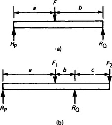
A man whose mass exerts a force F vertically downwards, standing on a wooden plank which is simply supported at its ends, may, for example, be represented by the beam diagram of Figure 36.3(a) if the mass of the plank is neglected. The forces exerted by the supports on the plank, Rp and RQ, act vertically upwards, and are called reactions.
(iii) When the forces acting are all in one plane, the algebraic sum of the moments can be taken about any point. For the beam in Figure 36.3(a), at equilibrium:
For the beam in Figure 36.3(b), at equilibrium:
(ii) taking moments about RQ, Rp (a + b) + F2c = F1b.
(iv) Typical practical applications of simply supported beams with point loadings include bridges, beams in buildings and beds of machine tools.
For example, for the beam shown in Figure 36.4, the force acting on support A, RA, and distance d are calculated as follows:
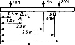
(Forces acting in an upward direction) = (Forces acting in a downward direction)

Taking moments about the left hand end of the beam and applying the principle of moments gives:
clockwise moments = anticlockwise moments

Shearing force and bending moments
4. As stated in para. 3, for equilibrium of a beam, the forces to the left of any section such as X in Figure 36.5, must balance the forces to the right. Also the moment about X of the forces to the left must balance the moment about X of the forces to the right.

Although for equilibrium the forces and moments cancel, the magnitude and nature of these forces and moments are important as they determine both the stresses at X and the beam curvature and deflection. The resultant force to the left of X and the resultant force to the right of X (forces or components of forces transverse to the beam), constitute a pair of forces tending to shear the beam at this section. Shearing force is defined as the force transverse to the beam at a given section tending to cause it to shear at that section.
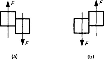
By convention, if the tendency is to shear as shown in Figure 36.6(a), the shearing force is regarded as positive, i.e. + F; if the tendency to shear is as shown in Figure 36.6(b), it is regarded as negative, i.e. − F.
5. The bending moment at a given section of a beam is defined as the resultant moment about that section of either all of the forces to its left — or of all of the forces to its right. In Figure 36.5 it is Mx or M’x. These moments, clockwise to the left and anticlockwise to the right, will cause the beam to bend concave upwards, called ‘sagging’. By convention this is regarded as positive bending (i.e. the bending moment is a positive bending moment). Where the curvature produced is concave downwards (called ‘hogging’), the bending moment is regarded as negative.
The values of shearing force and bending moment will usually vary along a beam. Diagrams showing the shearing force and bending moment for all sections of a beam are called shearing force and bending moment diagrams respectively.
Shearing forces and shearing force diagrams are less important than bending moments, but can be very useful in giving pointers to the more important bending moment diagrams. For example, wherever the shearing force is zero, the bending moment will be a maximum or a minimum. The shearing force and bending moment diagrams for the beam shown in Figure 36.7 are obtained as follows:

It is first necessary to calculate the reactions at A and B. The beam is simply-supported at A and B which means that it rests on supports at these points giving vertical reactions. The general conditions for equilibrium require that the resultant moment about any point must be zero, and total upward force must equal total downward force. Therefore, taking moments about A, the moment of RB must balance the moment of the load at C:

Immediately to the right of A the shearing force is due to RA and is therefore 9 kN. As this force to the left of the section considered, is upwards, the shearing force is positive. The shearing force is the same for all points between A and C as no other forces come on the beam between these points.
When a point to the right of C is considered, the load at C as well as RA must be considered, or alternatively, RB on its own. The shearing force is 15 kN, either obtained from RB = 15 kN, or from load at C - RA = 15 kN. For any point between C and B the force to the right is upwards and the shearing force is therefore negative. It should be noted that the shearing force changes suddenly at C.
The bending moment at A is zero, as there are no forces to its left. At a point 1 m to the right of A the moment of the only force RA to the left of the point is RA × 1 m = 9 kNm. As this moment to the left is clockwise the bending moment is positive, i.e. it is + 9 kNm. At points 2 m, 3 m, 4 m and 5 m to the right of A the bending moments are respectively:
RA × 2 m = 9 kN × 2 m = 18 kNm
RA × 3 m = 9 kN × 3 m = 27 kNm
RA × 4 m = 9 kN × 4 m = 36 kNm
RA × 5 m = 9 kN × 5 m = 45 kNm
All are positive bending moments.
For points to the right of C, the load at C as well as RA must be considered or, more simply, RB alone can be used. At points 5 m, 6 m and 7 m from A the bending moments are respectively:
RB × 3 m = 15 kN × 3 m = 45 kNm
RB × 2 m = 15 kN × 2 m = 30 kNm
RB × 1 m = 15 kN × 1 m = 15 kNm
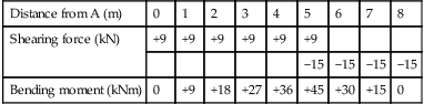
As these moments to the right of the points considered are anticlockwise they are all positive bending moments. At B the bending moment is zero as there is no force to its right. The results are summarised in the table below.
| Distance from A (m) | 0 | 1 | 2 | 3 | 4 | 5 | 6 | 7 | 8 |
| Shearing force (kN) | +9 | +9 | +9 | +9 | +9 | +9 | |||
| −15 | −15 | −15 | −15 | ||||||
| Bending moment (kNm) | 0 | +9 | +18 | +27 | +36 | +45 | +30 | +15 | 0 |
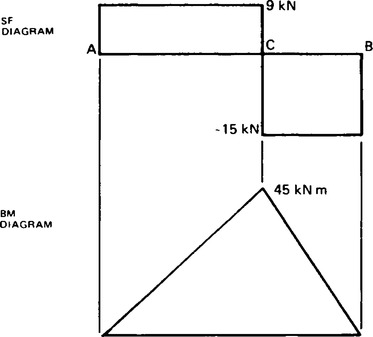
Making use of the above values, the diagrams are as shown (in the usual manner) in Figure 36.8. A stepped shearing force diagram, with horizontal and vertical lines only, is always obtained when the beam carries concentrated loads only. A sudden change in shearing force occurs where the concentrated loads, including the reactions at supports, occur. For this type of simple loading the bending moment diagram always consists of straight lines, usually sloping. Sudden changes of bending moment cannot occur except in the unusual circumstances of a moment being applied to a beam as distinct from a load.
Bending stress
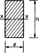
The second moments of area of the beam sections most commonly met with are (about the central axis XX):
(a) Solid rectangle (Figure 36.9).
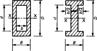
(b) Symmetrical hollow rectangle or I section (Figure 36.10)
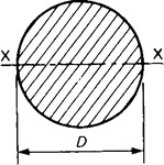
(c) Solid rod (Figure 36.11)
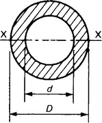
(d) Tube (Figure 36.12)
The neutral axis of any section, where bending produces no strain and therefore no stress, always passes through the centroid of the section. For the symmetrical sections listed above this means that for vertical loading the neutral axis is the horizontal axis of symmetry.
For example, let the maximum bending moment on a beam be 120 Nm. If the beam section is rectangular 18 mm wide and 36 mm deep, the maximum bending stress is calculated as follows:
Second moment of area of section about the neutral axis,
Maximum distance from neutral axis,
Since σ/y = M/I then the maximum bending stress σ will occur where M and y have their maximum values, i.e.