
Basic d.c. circuit theory
Publisher Summary
This chapter presents the basic direct current (d.c.) circuit theory. There are several symbols that are used for the components in electrical circuit diagrams. All substances are made from elements and the smallest particle to which an element can be reduced is called an atom. An atom consists of electrons that can be considered to be orbiting around a central nucleus containing protons and neutrons. Conductors are materials having electrons that are loosely connected to the nucleus and can easily move through the material from one atom to another. Insulators are materials whose electrons are held firmlyto their nucleus. The flow of electric current is subject to friction. This friction, or opposition, is called resistance R and is the property of aconductor that limits current. A fuse is used to prevent overloading of electrical circuits. A fuse is placed in an electrical circuit and if the current becomes too largethe fuse wire melts and so breaks the circuit.
Standard symbols for electrical components
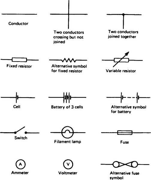
1. Symbols are used for components in electrical circuit diagrams and some of the more common ones are shown in Figure 5.1
(i) All substances are made from elements and the smallest particle to which an element can be reduced is called an atom.
(ii) An atom consists of electrons which can be considered to be orbiting around a central nucleus containing protons and neutrons.
(iii) An electron possesses a negative charge, a proton a positive charge and a neutron has no charge.
(iv) There is a force of attraction between oppositely charged bodies and a force of repulsion between similarly charged bodies.
(v) The force between two charged bodies depends on the amount of charge on the bodies and their distance apart.
(vi) Conductors are materials having electrons that are loosely connected to the nucleus and can easily move through the material from one atom to another. Insulators are materials whose electrons are held firmly to their nucleus.
(vii) A drift of electrons in the same direction constitutes an electric current.
(viii) The unit of charge is the coulomb, C, and when 1 coulomb of charge is transferred in 1 second a current of 1 ampere flows in the conductor. This electric current I is the rate of flow of charge in a circuit. The unit of current is the ampere, A.
(ix) For a continuous current to flow between two points in a circuit a potential difference (p.d.) or voltage, V, is required between them; a complete conducting path is necessary to and from the source of electrical energy. The unit of p.d. is the volt, V.
(x) Figure 5.2 shows a cell connected across a filament lamp. Current flow, by convention, is considered as flowing from the positive terminal of the cell, around the circuit to the negative terminal.

3. The flow of electric current is subject to friction. This friction, or opposition, is called resistance R and is the property of a conductor that limits current. The unit of resistance is the ohm, Ω. 1 ohm is defined as the resistance which will have a current of 1 ampere flowing through it when 1 volt is connected across it,
4. The reciprocal of resistance is called conductance and is measured in siemens (S). Thus
Electrical measuring instruments
(i) An ammeter is an instrument used to measure current and must be connected in series with the circuit. Figure 5.2 shows an ammeter connected in series with the lamp to measure the current flowing through it. Since all the current in the circuit passes through the ammeter it must have a very low resistance.
(ii) A voltmeter is an instrument used to measure p.d. and must be connected in parallel with the part of the circuit whose p.d. is required. In Figure 5.2, a voltmeter is connected in parallel with the lamp to measure the p.d. across it. To avoid a significant current flowing through it a voltmeter must have a very high resistance.
(iii) An ohmmeter is an instrument for measuring resistance.
(iv) A multimeter, or universal instrument, may be used to measure voltage, current and resistance. An ‘Avometer’ is a typical example.
(v) The cathode ray oscilloscope (CRO) may be used to observe waveforms and to measure voltages and currents. The display of a CRO involves a spot of light moving across a screen. The amount by which the spot is deflected from its initial position depends on the p.d. applied to the terminals of the CRO and the range selected. The displacement is calibrated in ‘volts per cm’. For example, if the spot is deflected 3 cm and the volts/cm switch is on 10 V/cm then the magnetude of the p.d. is 3 cm x 10 V/cm, i.e., 30 V. (See chapter 23,page 205).
Linear and non-linear devices
6. Figure 5.3 shows a circuit in which current I can be varied by the variable resistor R2. For various settings of R2, the current flowing in resistor R1 displayed on the ammeter, and the p.d. across R1 displayed on the voltmeter, are noted and a graph is plotted of p.d. against current. The result is shown in Figure 5.4(a) where the straight line graph passing through the origin indicates that current is directly proportional to the p.d. Since the gradient i.e. p.d./current is constant, resistance R1 is constant. A resistor is thus an example of a linear device.


If the resistor R1 in Figure 5.3 is replaced by a component such as a lamp then the graph shown in Figure 5.4(b) results when values of p.d. are noted for various current readings. Since the gradient is changing the lamp is an example of a non-linear device.
7. Ohm’s law states that the current I flowing in a circuit is directly proportional to the applied voltage V and inversely proportional to the resistant R, provided the resistance remains constant. Thus:
(i) A conductor is a material having a low resistance which allows electric current to flow in it. All metals are conductors and some examples include copper, aluminium, brass, platinum, silver, gold and also carbon.
(ii) An insulator is a material having a high resistance which does not allow electric current to flow in it. Some examples of insulators include plastic, rubber, glass, porcelain, air, paper, cork, mica, ceramics and certain oils.
Series circuit
9. Figure 5.5 shows threee resistors R1, R2 and R3 connected end to end, i.e., in series with a battery source of V volts. Since the circuit is closed a current I will flow and the p.d. across each resistor may be determined from the voltmeter readings V1, V2 and V3. In a series circuit:
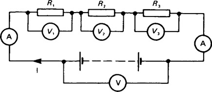
(a) the current I is the same in all parts of the circuit and hence the same reading is found on each of the ammeters shown, and
(b) the sum of the voltages V1, V2 and V3 is equal to the total applied voltage, V, i.e.
V1 + IR1, V2 = IR2, V3 = IR3 and V = IR
where R is the total circuit resistance.
Dividing throughout by I gives
Thus for a series circuit, the total resistance is obtained by adding together the values of the separate resistances.
10. The voltage distribution for the circuit shown in Figure 5.6(a) is given by:

The circuit shown in Figure 5.6(b) is often referred to as a potential divider circuit. Such a circuit can consist of a number of similar elements in series connected across a voltage source, voltages being taken from connections in-between the elements. Frequently the potential divider consists of two resistors as shown in Figure 5.6(b) where
Where a continuously variable voltage is required from a fixed supply a single resistor with a sliding contact is used. Such a device is known as a potentiometer.
Parallel circuit
11. Figure 5.7 shows three resistors, R1, R2 and R3 connected across each other, i.e. in parallel, across a battery source of V volts. In a parallel circuit:

(a) the sum of the currents I1, I2 and I3 is equal to the total circuit current, I, i.e. I = I1 + I2 + I3, and
(b) the source p.d., V volts, is the same across each of the resistors.
where R is the total circuit resistance.
Dividing throughout by V gives:
This equation must be used when finding the total resistance R of a parallel circuit.
12. For the special case of two resistors in parallel:
13. The current division for the circuit shown in Figure 5.8 is given by:

Wiring lamps in series and in parallel
Series connection
14. Figure 5.9 shows three lamps, each rated at 240 V, connected in series across a 240 V supply.

(i) Each lamp has only ![]() V, i.e. 80 V across it and thus each lamp glows dimly.
V, i.e. 80 V across it and thus each lamp glows dimly.
(ii) If another lamp of similar rating is added in series with the other three lamps then each lamp now has ![]() V, i.e. 60 V across it and each now glows even more dimly.
V, i.e. 60 V across it and each now glows even more dimly.
(iii) If a lamp is removed from the circuit or if a lamp develops a fault (i.e. an open circuit) or if the switch is opened then the circuit is broken, no current flows, and the remaining lamps will not light up.
(iv) Less cable is required for a series connection than for a parallel one.
The series connection of lamps is usually limited to decorative lighting such as for Christmas tree lights.
Parallel connection
Figure 5.10 shows three similar lamps, each rated at 240 V, connected in parallel across a 240 V supply.

(i) Each lamp has 240 V across it and thus each will glow brilliantly at their rated voltage.
(ii) If any lamp is removed from the circuit or develops a fault (open circuit) or a switch is opened, the remaining lamps are unaffected.
(iii) The addition of further similar lamps in parallel does not affect the brightness of the other lamps.
(iv) More cable is required for parallel connection than for a series one.
The parallel connection of lamps is the most widely used in electrical installations.
15. Power P in an electrical circuit is given by the product of potential difference V and current I. The unit of power is the watt, W.
Substituting for V in (1) gives:
Substituting for I in (1) gives:
There are thus three possible formulae which may be used for calculating power.
16. Electrical energy = power × time.
If the power is measured in watts and the time in seconds then the unit of energy is watt-seconds or joules. If the power is measured in kilowatts and the time in hours then the unit of energy is kilowatt-hours, often called the ‘unit of electricity’. The ‘electricity meter’ in the home records the number of kilowatt-hours used and is thus an energy meter.

(i) The three main effects of an electric current are:
Magnetic effect: bells, relays, motors, generators, transformers, telephones, car-ignition and lifting magnets. Chemical effect: primary and secondary cells and electroplating.
Heating effect: cookers, water heaters, electric fires, irons, furnaces, kettles and soldering irons.
18. A fuse is used to prevent overloading of electrical circuits.
The fuse, which is made of material having a low melting point, utilizes the heating effect of an electric current. A fuse is placed in an electrical circuit and if the current becomes too large the fuse wire melts and so breaks the circuit. A circuit diagram symbol for a fuse is shown in Figure 5.1, page 16.
Resistance variation
(i) Resistance, R, is directly proportional to length, l, of a conductor, i.e. R ∝ l. Thus, for example, if the length of a piece of wire is doubled, then the resistance is doubled.
(ii) Resistance, R, is inversely proportional to cross-sectional area, a, of conductor, i.e. R ∝ (1/a). Thus, for example, if the cross-sectional area of a piece of wire is doubled then the resistance is halved.
(iii) Since R ∝ I and R ∝ (1/a) then R ∝ (1/a). By inserting a constant of proportionality into this relationship the type of material used may be taken into account. The constant of proportionality is known as the resistivity of the material and is given the symbol ρ (rho).
ρ is measured in ohm metres (Ωm). The value of the resistivity is that resistance of a unit cube of the material measured between opposite faces of the cube.
(iv) Resistivity varies with temperature and some typical values of resistivities measured at about room temperature are given below:
Copper, 1.7 × 10⁻⁸ Ωm (or 0.017 µΩm)
Aluminium 2.6 × 10⁻⁸ Ωm (or 0.026 µΩm)
Carbon (graphite) 10 × 10-8 Ωm (0.10 µΩm)
Glass 1 × 10¹⁰ Ωm (or 104 µΩm)
Mica 1 × 10¹³ Ωm (or 107 µΩm).
Note that good conductors of electricity have a low value of resistivity and good insulators have a high value of resistivity.
(i) In general, as the temperature of a material increases, most conductors increase in resistance, insulators decrease in resistance whilst the resistance of some special alloys remain almost constant.
(ii) The temperature coefficient of resistance of a material is the increase in the resistance of a 1 Ω resistor of that material when it is subjected to a rise of temperature of 1°C. The symbol used for the temperature coefficient of resistance is α (alpha). Thus, if some copper wire of resistance 1 Ω is heated through 1°C and its resistance is then measured as 1.0043 Ω then
The units are usually expressed only as ‘per °C’, i.e. α =0.0043/°C for copper. If the I Ω resistor of copper is heated through 100°C then the resistance at 100°C would be
(iii) If the resistance of a material at 0°C is known, the resistance at any other temperature can be determined from:
Rθ = resistance at temperature θ°C;
α = temperature coefficient of resistance at 0°C.
(iv) If the resistance at 0°C is not known, but is known at some other temperature θ1, then the resistance at any temperature can be found as follows:
R1 = R0 (1 + α0θ1) and R2 = R0(1 + α0θ2)
Dividing one equation by the other gives:
where R2 = resistance at temperature θ2.
(v) If the resistance of a material at room temperature (approximately 20°C), R20, and the temperature coefficient of resistance at 20°C, α20 are known then the resistance Rθ at temperature 0°C is given by:
(vi) Some typical values of temperature coefficient of resistance measured at 0°C are given below:
| Copper | 0.00431°C |
| Aluminium | 0.0038/°C |
| Nickel | 0.0062/°C |
| Carbon | –0.000481°C |
| Constantan | 0 |
| Eureka | 0.00001 /°C |
(Note that the negative sign for carbon indicates that its resistance falls with increase of temperature.)