
Electromagnetism and magnetic circuits
Publisher Summary
This chapter focuses on electromagnetism and magnetic circuits. The area around a magnet is called the magnetic field, and it is in this area that the effects of the magnetic force produced by the magnet can be detected. Magnetic fields are produced by electric currents as well as by permanent magnets. The field forms a circular pattern with the current carrying conductor at the center. An electromagnet, which is a solenoid wound on an ironcore, provides the basis for many items of electrical equipment, including electric bells, relays, and lifting magnets. Magnetic flux is the amount of magnetic field—or thenumber of lines of force—produced by a magnetic source, whereas magnetic flux density is the amount of flux passing through a defined area that is perpendicular to the direction of the flux.
Magnetism
1. A permanent magnet is a piece of ferromagnetic material (such as iron, nickel or cobalt) which has properties of attracting other pieces of these materials.
2. The area around a magnet is called the magnetic field and it is in this area that the effects of the magnetic force produced by the magnet can be detected.
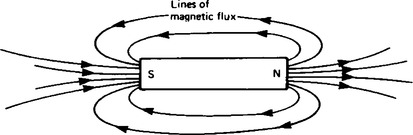
3. The magnetic field of a bar magnet can be represented pictorially by the ‘lines of force’ (or lines of ‘magnetic flux’ as they are called) as shown in Figure 10.1. Such a field pattern can be produced by placing iron filings in the vicinity of the magnet. The field direction at any point is taken as that in which the north-seeking pole of a compass needle points when suspended in the field. External to the magnet the direction of the field is north to south.
4. The laws of magnetic attraction and repulsion can be demonstrated by using two bar magnets. In Figure 10.2(a), with unlike poles adjacent, attraction occurs. In Figure 10.2(b), with like poles adjacent, repulsion occurs.

Electromagnetism
5. Magnetic fields are produced by electric currents as well as by permanent magnets. The field forms a circular pattern with the current carrying conductor at the centre. The effect is portrayed in Figure 10.3 where the convention adopted is:

(a) current flowing away from the viewer is shown by ![]() – can be thought of as the feathered end of the shaft of an arrow
– can be thought of as the feathered end of the shaft of an arrow
(b) current flowing towards the viewer is shown by ![]() – can be thought of as the tip of an arrow.
– can be thought of as the tip of an arrow.
6. The direction of the fields in Figure 10.3 is remembered by the screw rule which states: “If a normal right-hand thread screw is screwed along the conductor in the direction of the current, the direction of rotation of the screw is in the direction of the magnetic field’.
7. A magnetic field produced by a long coil, or solenoid, is shown in Figure 10.4 and is seen to be similar to that of a bar magnet shown in Figure 10.1. If the solenoid is wound on an iron bar an even stronger field is produced. The direction of the field produced by current I is determined by a compass and is remembered by either:

(a) the screw rule, which states that if a normal right hand thread screw is placed along the axis of the solenoid and is screwed in the direction of the current it moves in the direction of the magnetic field inside of the solenoid (i.e. points in the direction of the north pole), or
(b) the grip rule, which states that if the coil is gripped with the right hand with the fingers pointing in the direction of the current, then the thumb, outstretched parallel to the axis of the solenoid, points in the direction of the magnetic field inside the solenoid (i.e. points in the direction of the north pole).
8. An electromagnet, which is a solenoid wound on an iron core, provides the basis of many items of electrical equipment, examples including electric bells, relays and lifting magnets.
(i) A simple electric bell circuit is shown in Figure 10.5. When the switch S is closed a current passes through the coil. The iron-cored solenoid is energised, the soft iron armature is attracted to the electromagnet and the striker hits the gong. When the switch S is opened the coil becomes demagnetised and the spring steel strip pulls the armature back to its original position. This is the principle of operation of an electric bell.

(ii) A typical relay circuit connected to an alarm device is shown in Figure 10.6. When the switch S is closed a current passes through the coil and the iron-cored solenoid is energised. The hinged soft iron armature is attracted to the electromagnet and pushes against the two fixed contacts so that they are connected together, thus closing the electric circuit to be controlled – in this case, an alarm circuit. The alarm sounds for as long as the current flows in the coil.

(iii) A typical scrap-metal yard lifting magnet showing the plan and elevation is shown in Figure 10.7. When current is passed through the coil, the iron core becomes magnetised (i.e., an electromagnet) and this will attract to it other pieces of magnetic material. When the circuit is broken the iron core becomes demagnetised which releases the materials being lifted.

(i) Magnetic flux is the amount of magnetic field (or the number of lines of force) produced by a magnetic source.
(ii) The symbol for magnetic flux is Φ (Greek letter ‘phi’).
(i) Magnetic flux density is the amount of flux passing through a defined area that is perpendicular to the direction of the flux.
(ii) The symbol for magnetic flux density is B.
(iii) The unit of magnetic flux density is the tesla, T, where 1 T = 1 Wb/m2.
(i) If a current carrying conductor is placed in a magnetic field produced by permanent magnets then the fields due to the current carrying conductor and the permanent magnets intersect and cause a force to be exerted on the conductor. The force on the current carrying conductor in a magnetic field depends upon:
(i) the intensity of the field, B teslas;
(ii) the strength of the current, i amperes;
(iii) the length of the conductor perpendicular to the magnetic field, l metres; and
(ii) When the magnetic field, the current and the conductor are mutually at right angles then:
(iii) When the conductor and the field are at an angle θ° to each other then:
(iv) Since when the magnetic field, current and conductor are mutually at right angles, F = BI l, the magnetic flux density B may be defined by ![]() , i.e. a field intensity of 1 T is exerted on 1 m of a conductor when the conductor carries a current of 1 A.
, i.e. a field intensity of 1 T is exerted on 1 m of a conductor when the conductor carries a current of 1 A.
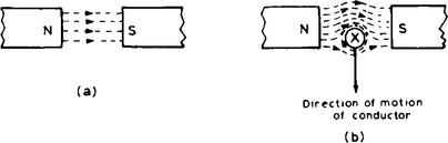
12. If the current-carrying conductor shown in Figure 10.3(a) is placed in the magnetic field shown in Figure 10.8(a), then the two fields interact and cause a force to be exerted on the conductor as shown in Figure 10.8(b). The field is strengthened above the conductor and weakened below, thus tending to move the conductor downwards. This is the basic principle of operation of the electric motor (see para 14) and the moving coil instrument (see page 199).
13. The direction of the force exerted on a conductor can be predetermined by using Fleming’s left-hand rule (often called the motor rule), which states:
‘Let the thumb, first finger and second finger of the left-hand be extended such that they are all at right angles to each other, as shown in Figure 10.9. If the first finger points in the direction of the magnetic field, the second finger points in the direction of the current, then the thumb will point in the direction of the motion of the conductor.’

Principle of operation of a d.c. motor
14. A rectangular coil which is free to rotate about a fixed axis is shown placed inside a magnetic field produced by permanent magnets in Figure 10.10. A direct current is fed into the coil via carbon brushes bearing on a commutator, which consists of a metal ring split into two halves separated by insulation. When current flows in the coil, a magnetic field is set up around the coil which interacts with the magnetic field produced by the magnets. This causes a force F to be exerted on the current carrying conductor, which, by Fleming’s left-hand rule (see para 13) is downwards between points A and B and upwards between C and D for the current direction shown. This causes a torque and the coil rotates anticlockwise.
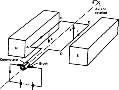
When the coil has turned through 90° from the position shown in Figure 10.10 the brushes connected to the positive and negative terminals of the supply make contact with different halves of the commutator ring, thus reversing the direction of the current flow in the conductor. If the current is not reversed and the coil rotates past this position the forces acting on it change direction and it rotates in the opposite direction thus never making more than half a revolution. The current direction is reversed every time the coil swings through the vertical position and thus the coil rotates anticlockwise for as long as the current flows. This is the principle of operation of a d.c. motor which is thus a device that takes in electrical energy and converts it into mechanical energy.
Magnetic circuits
15. Magnetomotive force (mmf), Fm = NI ampere-turns (At), where N = number of conductors (or turns) and I = current in amperes.
Since ‘turns’ has no units, the SI unit of mmf is the ampere, but to avoid any possible confusion ‘ampere-turns’, (A t) are used in this chapter.
16. Magnetic field strength, or magnetising force
where l = mean length of flux path in metres.
17. For air, or any non-magnetic medium, the ratio of magnetic flux density to magnetising force is a constant, i.e.
This constant is µ0, the permeability of free space (or the magnetic space constant) and is equal to 4π × 10-7 H/m.
Hence, for a non-magnetic medium, ![]()
where µr is the relative permeability, and is defined as
Its value varies with the type of magnetic material and since µr is a ratio of flux densities, it has no units. From its definition, µr for air is 1.
19. µ0µr = µ, called the absolute permeability.
20. By plotting measured values of flux density B against magnetic field strength H, a magnetisation curve (or B–H curve) is produced. For non-magnetic materials this is a straight line. Typical curves for four magnetic materials are shown in Figure 10.11.

21. The relative permeability of a ferromagnetic material is proportional to the slope of the B – H curve and thus varies with the magnetic field strength. The approximate range of values of relative permeability µr for some common magnetic materials are:
Cast iron µr = 100 − 250; Mild steel µr = 200 − 800
Silicon iron µr = 1000 − 5000; Cast steel µr = 300 − 900
Mumetal µr = 200 − 5000; Stalloy µr = 500 − 6000
22. The ‘magnetic resistance’ of a magnetic circuit to the presence of magnetic flux is called reluctance. The symbol for reluctance is S (or Rm).
24. The unit of reluctance is 1/H (or H-1) or At/Wb.
25. For a series magnetic circuit having n parts, the total reluctance S is given by: S=S1 + S2+ …+Sn. (This is similar to resistors connected in series in an electrical circuit.)
Comparison between electrical and magnetic quantities
| Electric circuit | Magnetic circuit |
| emf E (V) | mmf Fm (At) |
| current I (A) | flux Φ (Wb) |
| resistance R (Ω) | reluctance S (H−1) |
| I = |
Φ = |
| R = |
S = |

27. Ferromagnetic materials have a low reluctance and can be used as magnetic screens to prevent magnetic fields affecting materials within the screen.
28. Hysteresis is the ‘lagging’ effect of flux density B whenever there are changes in the magnetic field strength H.
29. When an initially unmagnetised ferromagnetic material is subjected to a varying magnetic field strength H, the flux density B produced in the material varies as shown in Figure 10.12, the arrows indicating the direction of the cycle. Figure 10.12 is known as the hysteresis loop.
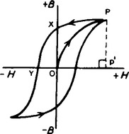
OX= residual flux density or remanence
30. Hysteresis results in a dissipation of energy which appears as a heating of the magnetic material. The energy loss associated with hysteresis is proportional to the areas of the hysteresis loop.
31. The area of a hysteresis loop varies with the type of material. The area, and thus the energy loss, is much greater for hard materials than for soft materials.