
a.c. motors
Publisher Summary
This chapter focuses on alternating current (a.c.). Two principal types of a.c. motors are in widespread use, these being induction motors and synchronous motors. Each of these types may be further subdivided into those being run from a three-phase industrial supply, called 3-phase motors, and those largely in domestic use, called single-phase motors. In a three-phase induction motor, the magnetic field rotates and this has the advantage that no external electrical connections to the rotor need be made. The result is a motor that:(1) is cheap and robust, (2) is explosion proof because of the absence of a commutator or slip-rings and brushes with their associated sparking, (3) requires little or no skilled maintenance, and (4) has self-starting properties when switched to a supply with no additional expenditure on auxiliary equipment. Three-phase synchronous motors normally have two windings, a three-phase stator winding to produce a rotatingmagnetic field and a rotor winding supplied by a direct current tomagnetise the rotor. The rotor is locked magnetically to the rotating magnetic field and for a constant frequency supply, the rotor runs at a constant speed that is directly proportional to the supply frequency.
1. Two principal types of a.c. motors are in widespread use, these being induction motors and synchronous motors. Each of these types may be further subdivided into those being run from a three-phase industrial supply, called 3-phase motors and those largely in domestic use, called single-phase motors.
Three-phase induction motors
2. In d.c. motors, introduced in Chapter 21, conductors on a rotating armature pass through a stationary magnetic field. In a three-phase induction motor, the magnetic field rotates and this has the advantage that no external electrical connections to the rotor need be made. The result is a motor which: (i) is cheap and robust, (ii) is explosion proof, due to the absence of a commutator or slip-rings and brushes with their associated sparking, (iii) requires little or no skilled maintenance, and (iv) has self starting properties when switched to a supply with no additional expenditure on auxiliary equipment. The principal disadvantage of a three-phase induction motor is that its speed cannot be readily adjusted.
3. Production of a rotating magnetic field. When a three-phase supply is connected to symmetrical three-phase stator windings, the currents flowing in the windings produce a magnetic field. This magnetic field is constant in magnitude and rotates at constant speed as shown below, and is called the synchronous speed.
With reference to Figure 22.1, the windings are represented by three single-loop conductors, one for each phase, marked RSRF, YSYF and BsBF, the S and F signifying start and finish. In practice, each phase winding comprises many turns and is distributed around the stator; the single-loop approach is for clarity only.
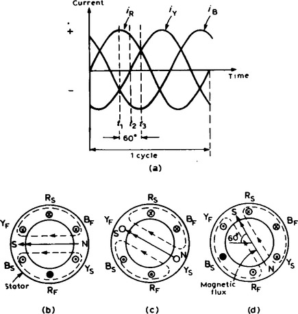
When the stator windings are connected to a three-phase supply, the current flowing in each winding varies with time and is as shown in Figure 22.1(a). If the value of current in a winding is positive, the assumption is made that it flows from start to finish of the winding, i.e. if it is the red-phase, current flows from Rs to RF,
i.e. away from the viewer in Rs and towards the viewer in RF. When the value of current is negative, the assumption is made that it flows from finish to start, i.e. towards the viewer in an ’S’ winding and away from the viewer in an ’F’ winding.
At time, say t1 shown in Figure 22.1(a), the current flowing in the red phase is a maximum possible value. At the same time, t1, the currents flowing in the yellow and blue phases are both 0.5 times the maximum value and are negative. The current distribution in the stator windings is therefore as shown in Figure 22.1 (b), in which current flows away from the viewer (shown as X) in Rs since it is positive but towards the viewer (shown as ˙) in YS and Bs, since these are negative. The resulting magnetic field is as shown, due to the ’solenoid’ action and application of the corkscrew rule.
A short time later at time t2, the current flowing in the red phase has fallen to about 0.87 times its maximum value and is positive, the current in the yellow phase is zero and the current in the blue phase is about 0.87 times its maximum value and is negative. Hence the currents and resultant magnetic field are as shown in Figure 22.1(c). At time t3, the currents in red and yellow phases are 0.5 of their maximum values and the current in the blue phase is a maximum negative value. The currents and resultant magnetic field are as shown in Figure 22.1(d).
Similar diagrams to Figure 22.1(b), (c), (d) can be produced for all time values and these would show that the magnetic field travels through one revolution for each cycle of the supply voltage applied to the stator windings. By considering the flux values rather than the current values, it can be shown that the rotating magnetic field has a constant value of flux.
4. The rotating magnetic field produced by three phase windings could have been produced by rotating a permanent magnet’s north and south pole at synchronous speed (shown as N and Sat the ends of the flux phasors in Figure 22.1(b), (c) and (d)). Fur this reason, it is called a 2-pole system and an induction motor using three phase windings only is called a 2-pole induction motor.
If six windings displaced from one another by 60° are used, as shown in Figure 22.2(b), by drawing the current and resultant magnetic field diagrams at various time values, it may be shown that one cycle of the supply current to the stator windings causes the magnetic field to move through half a revolution. The current distribution in the stator windings is shown in Figure 22.2(b), for the time t shown in Figure 22.2(a).

It can be seen that for six windings on the stator, the magnetic flux produced is the same as that produced by rotating two permanent magnet north poles and two permanent magnet south poles at synchronous speed. This is called a 4-pole system and an induction motor using six phase windings is called a 4-pole induction motor. By increasing the number of phase windings the number of poles can be increased to any even number. In general, f is the frequency of the currents in the stator windings and the stator is wound to be equivalent to p pairs of poles, the speed of revolution of the rotating magnetic field, i.e. the synchronous speed, ns is given by:
5. The principle of operation of the three-phase induction motor
The stator of a three-phase induction motor is the stationary part corresponding to the yoke of a d.c. machine. It is wound to give a 2-pole, 4-pole, 6-pole, … rotating magnetic field, depending on the rotor speed required. The rotor, corresponding to the armature of a d.c. machine, is built up of laminated iron, to reduce eddy currents.
In the type most widely used, known as a squirrel-cage rotor, copper or aluminium bars are placed in slots cut in the laminated iron, the ends of the bars being welded or brazed into a heavy conducting ring, (see Figure 22.3(a)). A cross-sectional view of a three-phase induction motor is shown in Figure 22.3(b).

When a three-phase supply is connected to the stator windings, a rotating magnetic field is produced. As the magnetic flux cuts a bar on the rotor, an e.m.f. is induced in it and since it is joined, via the end conducting rings, to another bar one pole pitch away, a current flows in the bars. The magnetic field associated with this current flowing in the bars interacts with the rotating magnetic field and a force is produced, tending to turn the rotor in the same direction as the rotating magnetic field (see Figure 22.4).
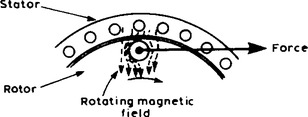
The force exerted by the rotor bars causes the rotor to turn in the direction of the rotating magnetic field. As the rotor speed increases, the rate at which the rotating magnetic field cuts the rotor bars is less and the frequency of the induced e.m.f.’s in the rotor bars is less. If the rotor runs at the same speed as the rotating magnetic field, no e.m.f.’s are induced in the rotor, hence there is no force on them and no torque on the rotor. Thus the rotor slows down. For this reason the rotor can never run at synchronous speed.
When there is no load on the rotor, the resistive forces due to windage and bearing friction are small and the rotor runs very nearly at synchronous speed. As the rotor is loaded, the speed falls and this causes an increase in the frequency of the induced e.m.f.’s in the rotor bars and hence the rotor current, force and torque increase. The difference between the rotor speed, nr, and the synchronous speed, ns, is called the slip speed, i.e.
The ratio (ns − nr)/ns is called the fractional slip or just the slip, s, and is usually expressed as a percentage. Thus
Typical values of slip between no load and full load are about 4% to 5% for small motors and ![]() to 2% for large motors.
to 2% for large motors.
Single-phase induction motor
8. The majority of ’fractional horse-power’ motors in domestic use for driving refrigerators, hot water pumps, fans, hair dryers and so on are single-phase induction motors. A single-phase supply connected to the stator winding only produces a pulsating magnetic field rather than the rotating magnetic field of a three-phase supply and facilities such as additional windings have to be built-in to the stators of these motors to give some torque at zero speed. There are several devices used and motors are named after the particular device used. Some of these include:
permanent-split capacitor induction motors, and so on.
9. Three-phase synchronous motors normally have two windings, a three-phase stator winding to produce a rotating magnetic field and a rotor winding supplied by a direct current to magnetise the rotor. The rotor is locked magnetically to the rotating magnetic field and for a constant frequency supply, the rotor runs at a constant speed which is directly proportional to the supply frequency.
These motors may be used on many of the loads driven by induction motors but (i) are normally more expensive, (ii) require both a.c. and d.c. supplies, (iii) require additional equipment to run them up to near to their normal running speed, so that the rotor magnetic field can be locked to the rotating magnetic field, and (iv) have higher maintenance costs than induction motors. However, they can run at higher efficiencies and when used adjacent to several induction motors can lead to a higher efficiency of the whole system (power factor correction). Due to the disadvantages listed above, three-phase synchronous motors are normally used for applications requiring a large power input, where savings due to higher efficiency outweigh the disadvantages. Their uses include driving large water pumps (power stations, water supply), driving rolling lines in steel mills and driving mine ventilating fans.
10. As for single-phase induction motors, single-phase synchronous motors require additional starting devices. They also require a direct current supply to the rotor or a permanent magnet built into the rotor. The former is rarely used and the principal uses of single-phase synchronous motors are largely limited to electric clocks, timing devices, record players and so on, these motors being called ’shaded-pole motors’. As for three-phase synchronous motors, they run at constant speed when connected to a constant frequency supply.