
Capacitors and capacitance
Publisher Summary
This chapter discusses the use of capacitors and capacitance. A capacitor is a device capable of storing electrical energy. Practical types of capacitor are characterised by the material used for their dielectric. The main types of capacitors are variable air, mica, paper, ceramics, plastic, and electrolytic. Every system of electrical conductors possesses capacitance. For example, there is capacitance among the conductors of overhead transmission lines and also among the wires of a telephone cable. In these examples, the capacitance is undesirable but has to be accepted, minimized or compensated for. There are other situations, such as in capacitors, where capacitance is a desirable property. The unit of capacitance is the farad F, which is defined as the capacitance of a capacitor when a p.d. of one volt appears across the plates when charged with one coulomb.
1. Electrostatics is the branch of electricity which is concerned with the study of electrical charges at rest. An electrostatic field accompanies a static charge and this is utilised in the capacitor.
2. Charged bodies attract or repel each other depending on the nature of the charge. The rule is: like charges repel, unlike charges attract.
3. A capacitor is a device capable of storing electrical energy. Figure 9.1 shows a capacitor consisting of a pair of parallel metal plates X and Y separated by an insulator, which could be air. Since the plates are electrical conductors each will contain a large number of mobile electrons. Since the plates are connected to a d.c. supply the electrons on plate X, which have a small negative charge, will be attracted to the positive pole of the supply and will be repelled from the negative pole of the supply on to plate Y. X will become positively charged due to its shortage of electrons whereas Y will have a negative charge due to its surplus of electrons.
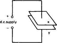
The difference in charge between the plates results in a p.d. existing between them, the flow of electrons dying away and ceasing when the p.d. between the plates equals the supply voltage. The plates are then said to be charged and there exists an electric field between them.
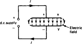
Figure 9.2 shows a side view of the plates with the field represented by ‘lines of electrical flux’. If the plates are disconnected from the supply and connected together through a resistor the surplus of electrons on the negative plate will flow through the resistor to the positive plate. This is called discharging. The current flow decreases to zero as the charges on the plates reduce. The current flowing in the resistor causes it to liberate heat showing that energy is stored in the electric field.
4. From Chapter 5, para 2(viii), page 15, charge Q stored is given by:
where I is the current in amperes and t the time in seconds.
5. A dielectric is an insulating medium separating charged surfaces.
6. Electric field strength, Electric force, or voltage gradient,
8. Charge Q on a capacitor is proportional to the applied voltage, V, i.e. Q∝V
9. Q = CV or C = Q/V, where the constant of proportionality, C, is the capacitance.
10 The unit of capacitance is the farad F (or more usually µF = 10-6 F or pF = 10-12 F), which is defined as the capacitance of a capacitor when a p.d. of one volt appears across the plates when charged with one coulomb.
11. Every system of electrical conductors possesses capacitance. For example, there is capacitance between the conductors of overhead transmission lines and also between the wires of a telephone cable. In these examples the capacitance is undesirable but has to be accepted, minimised or compensated for. There are other situations, such as in capacitors, where capacitance is a desirable property.
12. The ratio of electric flux density, D, to electric field strength, E, is called absolute permittivity, ε, of a dielectric.
13. Permittivity of free space is a constant, given by ε0 = 8.85 × 10⁻¹² F/m.
(εr has no units.) Examples of the values of εr include: air = 1, polythene = 2.3, mica = 3–7, glass = 5–10, ceramics = 6–1000.
15. Absolute permittivity, ε = ε0εr.
16. For a parallel plate capacitor, capacitance is proportional to area A, inversely proportional to the plate spacing (or dielectric thickness) d, and depends on the nature of the dielectric and the number of plates, n.
CT = C1 + C2 + C3+…+Cn (similar to resistors connected in series)
The charge on each capacitor is the same when connected in series.
19. The maximum amount of field strength that a dielectric can withstand is called the dielectric strength of the material.
20. The energy, W, stored by a capacitor is given by ![]() joules.
joules.
21. Practical types of capacitor are characterised by the material used for their dielectric. The main types include: variable air, mica, paper, ceramics, plastic and electrolytic.
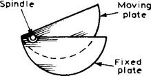
(a) Variable air capacitors. These usually consist of two sets of metal plates (i.e. aluminium) one fixed, the other variable. The set of moving plates rotate on a spindle as shown by the end view in Figure 9.3. As the moving plates are rotated through half a revolution, the meshing, and therefore the capacitance, varies from a minimum to a maximum value. Variable air capacitors are used in radio and electronic circuits where very low losses are required, or where a variable capacitance is needed. The maximum value of such capacitors is between 500 pF and 1000 pF.
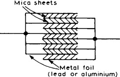
(b) Mica capacitors A typical older type construction is shown in Figure 9.4. Usually the whole capacitor is impregnated with wax and placed in a bakelite case. Mica is easily obtained in thin sheets and is a good insulator. However, mica is expensive and is not used in capacitors above about 0.1 µF. A modified form of mica capacitor is the silvered mica type. The mica is coated on both sides with a thin layer of silver which forms the plates. Capacitance is stable and less likely to change with age. Such capacitors have a constant capacitance with change of temperature, a high, working voltage rating and a long service life and are used in high frequency circuits with fixed values of capacitance up to about 1000 pF.
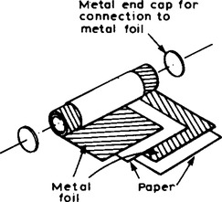
(c) Paper capacitors A typical paper capacitor is shown in Figure 9.5 where the length of the roll corresponds to the capacitance required. The whole is usually impregnated with oil or wax to exclude moisture, and then placed in a plastic or aluminium container for protection. Paper capacitors, up to about 1 µF, are made in various working voltages. Disadvantages of paper capacitors include variation in capacitance with temperature change and a shorter service life than most other types of capacitor.
(d) Ceramic capacitors These are made in various forms, each type of construction depending on the value of capacitance required. For high values, a tube of ceramic material is used as shown in the cross section of Figure 9.6. For smaller values the cup construction is used as shown in Figure 9.7, and for still smaller values the disc construction shown in Figure 9.8 is used.
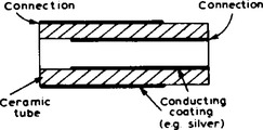

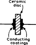
Certain ceramic materials have a very high permittivity and this enables capacitors of high capacitance to be made which are of small physical size with a high working voltage rating. Ceramic capacitors are available in the range 1 pF to 0.1 µF and may be used in high frequency electronic circuits subject to a wide range of temperature.
(e) Plastic capacitors Some plastic materials such as polystyrene and Teflon can be used as dielectrics. Construction is similar to the paper capacitor but using a plastic film instead of paper. Plastic capacitors operate well under conditions of high temperature, provide a precise value of capacitance, a very long service life and high reliability.
(f) Electrolytic capacitors Construction is similar to the paper capacitor with aluminium foil used for the plates and with a thick absorbent material, such as paper, impregnated with an electrolyte (ammonium borate), separating the plates. The finished capacitor is usually assembled in an aluminium container and hermetically sealed. Its operation depends on the formation of a thin aluminium oxide layer on the positive plate by electrolytic action when a suitable direct potential is maintained between the plates. This oxide layer is very thin and forms the dielectric. (The absorbent paper between the plates is a conductor and does not act as a dielectric.) Such capacitors must only be used on d.c. and must be connected with the correct polarity; if this is not done the capacitor will be destroyed since the oxide layer will be destroyed. Electrolytic capacitors are manufactured with working voltages from 6 V to 500 V, although accuracy is generally not very high. These capacitors possess a much larger capacitance than other types of capacitors of similar dimensions due to the oxide film being only a few microns thick. The fact that they can be used only on d.c. supplies limits their usefulness.
22. When a capacitor has been disconnected from the supply it may still be charged and it may retain this charge for some considerable time. Thus precautions must be taken to ensure that the capacitor is automatically discharged after the supply is switched off. This is done by connecting a high value resistor across the capacitor terminals.