
d.c. machines
Publisher Summary
This chapter provides an overview on direct current (d.c.). When the input to an electrical machine is electrical energy and the output is mechanical energy, the machine is called an electric motor. Thus, an electric motor converts electrical energy into mechanical energy. The efficiency of an electrical machine is the ratio of the output power to the input power and is usually expressed as a percentage. There are many conductors on the rotating partof a d.c. machine, and these are attached to many commutator segments. The basic parts of any d.c.machine area stationary part called the stator and a rotating part called the armature mounted in bearings housed in the stator. Furthermore, the two principal generator characteristics are the generated voltage/field current characteristic, called the open-circuit characteristic and the terminal voltage/load current characteristic, called the load characteristic.
1. When the input to an electrical machine is electrical energy (seen as applying a voltage to the electrical terminals of the machine), and the output is mechanical energy (seen as a rotating shaft), the machine is called an electric motor. Thus an electric motor converts electrical energy into mechanical energy.
2. When the input to an electrical machine is mechanical energy (seen as, say, a diesel motor, coupled to the machine by a shaft), and the output is electrical energy (seen as a voltage appearing at the electrical terminals of the machine), the machine is called a generator. Thus, a generator converts mechanical energy to electrical energy.
3. The efficiency of an electrical machine is the ratio of the output power to the input power and is usually expressed as a percentage. The Greek letter ’eta’, ’η’ is used to signify efficiency and since the units are power/power, then efficiency has no units. Thus:
4. The action of a commutator. In an electric motor, conductors rotate in a uniform magnetic field. A single-loop conductor mounted between permanent magnets is shown in Figure 21.1. A voltage is applied at point A and B in Figure 21.1(a).
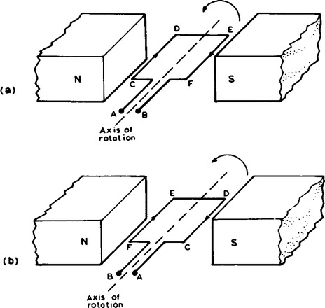
A force, F, acts on the loop due to the interaction of the magnetic field of the permanent magnets and the magnetic field created by the current flowing in the loop. This force is proportional to the flux density, B, the current flowing, I, and the effective length of the conductor, l, i.e. F = BIl. The force is made up of two parts, one acting vertically downwards due to the current flowing from C to D and the other acting vertically upwards due to the current flowing from E to F (from Fleming’s left hand rule). If the loop is free to rotate, then when it has rotated through 180°, the conductors are as shown in Figure 21.1(b). For rotation to continue in the same direction, it is necessary for the current flow to be as shown in Figure 21.1(b), i.e.
from D to C and from F to E. This apparent reversal in the direction of current flow is achieved by a process called commutation. With reference to Figure 21.2(a), when a direct voltage is applied at A and B, then as the single-loop conductor rotates, current flow will always be away from the commutator for the part of the conductor adjacent to the N-pole and towards the commutator for the part of the conductor adjacent to the S-pole. Thus the forces act to give continuous rotation in an anti-clockwise direction. The arrangement shown in Figure 21.2 is called a ’two-segment’ commutator and the voltage is applied to the rotating segments by stationary brushes (usually carbon blocks), which slide on the commutator material (usually copper), when rotation takes place.
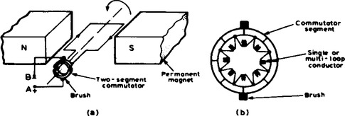
In practice, there are many conductors on the rotating part of a d.c. machine and these are attached to many commutator segments. A schematic diagram of a multi-segment commutator is shown in Figure 21.2(b).
5. D.C. machine construction. The basic parts of any d.c. machine are shown in Figure 21.3(b), and comprise:
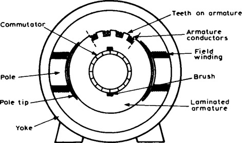
Current passing through this conductor creates an electromagnet (rather than the permanent magnets shown in Figures 21.1 and 21.2).
(b) A rotating part called the armature mounted in bearings housed in the stator and having,
(iv) a laminated cylinder of iron or steel called the core, on which teeth are cut to house the
(v) armature winding, i.e. a single or multi-loop conductor system and
(vi) the commutator (see para. 4).
where p is the number of pairs of poles, Φ is the flux in webers entering or leaving a pole and n is the speed of rotation in rev/s. Thus the average e.m.f. per conductor is 2pΦn volts. If there are Z conductors connected in series, the average e.m.f. generated is 2pΦnZ volts. For a given machine, the number of pairs of poles p and the number of conductors connected in series Z are constant, hence the generated e.m.f. is proportional to Φn. But 2πn is the angular velocity, ω in rad/s, hence the generated e.m.f E is proportional to Φ and to ω, i.e. generated e.m.f.,
7. The power on the shaft of a d.c. machine is the product of the torque and the angular velocity, i.e.
where T is the torque in Nm and ω is the angular velocity in rad/s. The power developed by the armature current is EIa watts, where E is the generated e.m.f. in volts and Ia is the armature current in amperes. If losses are neglected then Tω = EIa. But from para. 6, Eocϕω.
8. When the field winding of a d.c. machine is connected in parallel with the armature, as shown in Figure 21.4(a), the machine is said to be shunt wound.
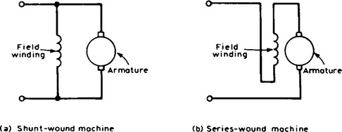
If the field winding is connected in series with the armature, as shown in Figure 21.4(b), then the machine is said to be series wound.
9. Depending on whether the electrical machine is series wound or shunt wound, it behaves differently when a load is applied. The behaviour of a d.c. machine under various conditions is shown by means of graphs, called characteristic curves or just characteristics. The characteristics shown in the paras below are theoretical, since they neglect the effects of such things as armature reaction and demagnetising ampere-turns.
Shunt-wound motor characteristics
10. The two principal characteristics are the torque/armature current and speed/armature current relationships. From these, the torque/speed relationship can be derived.
(i) The theoretical torque/armature current characteristic can be derived from the expression T ∝ Φ Ia (see para. 7). For a shunt-wound motor, the field winding is connected in parallel with the armature circuit and thus the applied voltage gives a constant field current, i.e. a shunt-wound motor is a constant flux machine. Since Φ is constant, it follows that T ∝ Ia, and the characteristic is as shown in Figure 21.5(a).
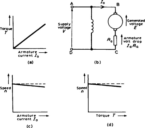
(ii) The armature circuit of a d.c. motor has resistance due to the armature winding and brushes, Ra, ohms, and when armature current Ia is flowing through it, there is a voltage drop of IaRa volts. In Figure 21.5(b) the armature resistance is shown as a separate resistor in the armature circuit to help understanding. Also, even though the machine is a motor, because conductors are rotating in a magnetic field, a voltage, E ∝ Φω, is generated by the armature conductors. By applying Kirchhoff’s voltage law to the armature circuit ABCD in Figure 21.5(b), the voltage equation is V = E + IaRa, i.e. E = V − IaRa. But from para. 6, E ∝ Φn, hence n ∝ E/Φ, i.e. speed of rotation,
For a shunt motor, V, Φ and Ra, are constants, hence as armature current Ia, increases, V − IaRa increases and V—IaR, decreases, and the speed is proportional to a quantity which is decreasing and is as shown in Figure 21.5(c). As the load on the shaft of the motor increases, Ia, increases and the speed drops slightly. In practice, the speed falls by about 10% between no-load and full-load on many d.c. shunt-wound motors.
(iii) Since torque is proportional to armature current (see (i) above), the theoretical speed/torque characteristic is as shown in Figure 21.5(d).
Series-wound motor characteristics
11. In a series motor, the armature current flows in the field winding and is equal to the supply current I (see Figure 21.4(b)).
(i) The torque/current characteristic It is shown in para. 7 that torque T ∝ ΦIa. Since the armature and field currents are the same current, I, in a series machine, then T ∝ ΦI over a limited range, before magnetic saturation of the magnetic circuit of the motor is reached (i.e. the linear portion of the B-H curve for the yoke, poles, air gap, brushes and armature in series). Thus Φ ∝ I and T ∝ I2. After magnetic saturation, Φ almost becomes a constant and T ∝ I. Thus the theoretical torque/current characteristic is as shown in Figure 21.6(a).
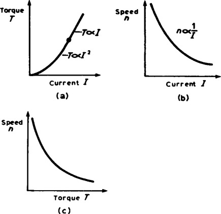
(ii) The speed/current characteristic It is shown in para. 10(ii) that ![]() . In a series motor, Ia = I and below the magnetic saturation level, Φ ∝ I. Thus n ∝ (V − IR)/I where R is the combined resistance of the series field and armature circuit. Since IR is small compared with V, then an approximate relationship for the speed is n ∝ 1/I. Hence the theoretical speed/current characteristic is as shown in Figure 21.6(b). The high speed at small values of current indicate that this type of motor must not be run on very light loads and invariably, such motors are permanently coupled to their loads.
. In a series motor, Ia = I and below the magnetic saturation level, Φ ∝ I. Thus n ∝ (V − IR)/I where R is the combined resistance of the series field and armature circuit. Since IR is small compared with V, then an approximate relationship for the speed is n ∝ 1/I. Hence the theoretical speed/current characteristic is as shown in Figure 21.6(b). The high speed at small values of current indicate that this type of motor must not be run on very light loads and invariably, such motors are permanently coupled to their loads.
(iii) The theoretical speed/torque characteristic may be derived from (i) and (ii) above by obtaining the torque and speed for various values of current and plotting the co-ordinates on the speed/torque characteristic. A typical speed/torque characteristic is shown in Figure 21.6(c).
Shunt-wound generator characteristics
12. The two principal generator characteristics are the generated voltage/field current characteristic, called the open-circuit characteristic and the terminal voltage/load current characteristic, called the load characteristic.
(i) The theoretical open-circuit characteristic The generated e.m.f., E, is proportional to Φω (see para. 6), hence at constant speed, since ω = 2πn, E ∝ Φ. Also the flux Φ is proportional to field current If until magnetic saturation of the iron circuit of the generator occurs. Hence the open circuit characteristic is as shown in Figure 21.7(a).
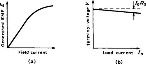
(ii) The theoretical load characteristic As the load current on a generator having constant field current and running at constant speed increases, the value of armature current increases, hence the armature volt drop, Ia Ra increases. The generated voltage E is larger than the terminal voltage V and the voltage equation for the armature circuit is V = E − Ia Since E is constant, V decreases with increasing load. The load characteristic is as shown in Figure 21.7(b). In practice, the fall in voltage is about 10% between no-load and full-load for many d.c. shunt-wound generators.
Series-wound generator characteristic
13. The load characteristic is the terminal voltage/current characteristic. The generated e.m.f., E, is proportional to Φω and at constant speed ω (= 2πn) is a constant. Thus E is proportional to Φ. For values of current below magnetic saturation of the yoke, poles, air gaps and armature core, the flux Φ is proportional to the current, hence E ∝ I.
For values of current above those required for magnetic saturation, the generated e.m.f. is approximately constant. The values of field resistance and armature resistance in a series wound machine are small, hence the terminal voltage V is very nearly equal to E. Thus the theoretical load characteristic is similar in shape to the characteristic shown in Figure 21.7(a).
In a series-wound generator, the field winding is in series with the armature and it is not possible to have a value of field current when the terminals are open circuited, thus it is not possible to obtain an open-circuit characteristic.
The d.c. motor starter
14. If a d.c. motor whose armature is stationary is switched directly to its supply voltage, it is likely that the fuses protecting the motor will burn out. This is because the armature resistance is small, frequently being less than 1 Ω. Thus, additional resistance must be added to the armature circuit at the instant of closing the switch to start the motor.
As the speed of the motor increases, the armature conductors are cutting flux and a generated voltage, acting in opposition to the applied voltage, is produced, which limits the flow of armature current. Thus the value of the additional armature resistance can then be reduced. When at normal running speed, the generated e.m.f. is such that no additional resistance is required in the armature circuit. To achieve this varying resistance in the armature circuit on starting, a d.c. motor starter is used, as shown in Figure 21.8.
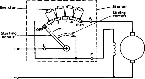
The starting handle is moved slowly in a clockwise direction to start the motor. For a shunt-wound motor, the field winding is connected to stud 1 or to L, via a sliding contact on the starting handle, to give maximum field current, hence maximum flux, hence maximum torque on starting, since T ∝ Φ Ia. A similar arrangement without the field connection is used for series motors.
Speed control of d.c. motors
(i) Shunt-wound motors The speed of a shunt-wound d.c. motor, n, is proportional to (V-IaRa)Φ (see para. 10). The speed is varied either by varying the value of flux, ϕ, or by varying the value of Ra. The former is achieved by using a variable resistor in series with the field winding, as shown in Figure 21.9(a), and such a resistor is called the shunt field regulator. As the value of resistance of the shunt field regulator is increased, the value of the field current, If, is decreased. This results in a decrease in the value of flux Φ, and hence an increase in the speed, since n ∝ 1/Φ. Thus only speeds above that given without a shunt field regulator can be obtained by this method. Speeds below those given by (V − IaRa)/Φ are obtained by increasing the resistance in the armature circuit, as shown in Figure 21.9(b), where
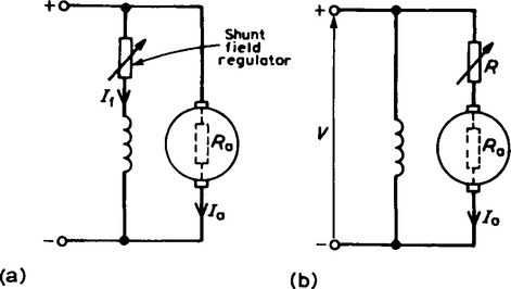
Since resistor R is in series with the armature, it carries the full armature current and results in a large power loss in large motors where a considerable speed reduction is required for long periods.
(ii) Series-wound motors The speed of a d.c. series-wound motor is given by:
where k is a constant, V is the terminal voltage, R is the combined resistance of the armature and series field and Φ is the flux.
Thus, a reduction in flux results in an increase in speed. This is achieved by putting a variable resistance in parallel with the field winding and reducing the field current, and hence flux, for a given value of supply current. A circuit diagram of this arrangement is shown in Figure 21.10(a), A variable resistor connected in parallel with the series-wound field to control speed is called a diverter. Speeds above those given with no diverter are obtained by this method.
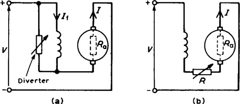
Speeds below normal are obtained by connecting a variable resistor in series with the field winding and armature circuit, as shown in Figure 21.10(b). This effectively increases the value of R in the equation
and thus reduces the speed. Since the additional resistor carries the full supply current, a large power loss is associated with large motors in which a considerable speed reduction is required for long periods.