
Coplanar forces acting at a point
Publisher Summary
This chapter focuses on coplanar forces acting at a point. When all forces are acting in the same plane, they are called coplanar whereas when forces act at the same time and at the same point, they are called concurrent/forces. For forces acting in the same direction and having the same line of action, the single force having the same effect as both of the forces, called the resultant force or just the resultant, is the arithmetic sum of the separate forces. When two forces do not have the same line of action, the magnitude and direction of the resultant force may be found by a procedure called vector addition of forces. There are two graphical methods of performing vector addition, known as the triangle of forces method and the parallelogram of forces method. For forces acting in opposite directions along the sameline of action, the resultant force is the arithmetic difference between the two forces. When three or more coplanar forces are acting at a point and the vector diagram closes, there is no resultant. The forces acting at the point are in equilibrium.
1. When forces are all acting in the same plane, they are called coplanar. When forces act at the same time and at the same point, they are called concurrent/forces.
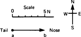
2. Force is a vector quantity and thus has both a magnitude and a direction. A vector can be represented graphically by a line drawn to scale in the direction of the line of action of the force. Vector quantities may be shown by using bold, lower case letters, thus ab in Figure 35.1 represents a force of 5 newtons acting in a direction due east.
The resultant of two coplanar forces
3. For two forces acting at a point, there are three possibilities.
(a) For forces acting in the same direction and having the same line of action, the single force having the same effect as both of the forces, called the resultant force or just the resultant, is the arithmetic sum of the separate forces. Forces of F1 and F2 acting at point P, as shown in Figure 35.2(a) have exactly the same effect on point P as force F shown in Figure 35.2(b), where F = F1 + F2 and acts in the same direction as F1 and F2. Thus, F is the resultant of F1 and F2.

(b) For forces acting in opposite directions along the same line of action, the resultant force is the arithmetic difference between the two forces. Forces of F1 and F2 acting at point P as shown in Figure 35.3(a), have exactly the same effect on point P as force F shown in Figure 35.3(b), where F = F2 − F1 and acts in the direction of F2, since F2 is greater than F1. Thus F is the resultant of F1 and F2.

(c) When two forces do not have the same line of action, the magnitude and direction of the resultant force may be found by a procedure called vector addition of forces. There are two graphical methods of performing vector addition, known as the triangle of forces method and the parallelogram of forces method.
The triangle of forces method
(i) Draw a vector representing one of the forces, using an appropriate scale and in the direction of its line of action.
(ii) From the nose of this vector and using the same scale, draw a vector representing the second force in the direction of its line of action.
(iii) The resultant vector is represented in both magnitude and direction by the vector drawn from the tail of the first vector to the nose of the second vector.
Thus, for example, to determine the magnitude and direction of the resultant of a force of 15 N acting horizontally to the right and a force of 20 N, inclined at an angle of 60° to the 15 N force, using the triangle of forces method: With reference to Figure 35.4 and using the above procedure:

(i) ab is drawn 15 units long horizontally;
(ii) from b, bc is drawn 20 units long, inclined at an angle of 60° to ab. (Note, in angular measure, an angle of 60° from ab means 60° in an anticlockwise direction.)
(iii) By measurement, the resultant ac is 30.5 units long inclined at an angle of 35° to ab.
Hence the resultant force is 30.5 N inclined at an angle of 35° to the 15 N force.
The parallelogram of forces method
(i) Draw a vector representing one of the forces, using an appropriate scale and in the direction of its line of action.
(ii) From the tail of this vector and using the same scale draw a vector representing the second force in the direction of its line of action.
(iii) Complete the parallelogram using the two vectors drawn in (i) and (ii) as two sides of the parallelogram.
(iv) The resultant force is represented in both magnitude and direction by the vector corresponding to the diagonal of the parallelogram drawn from the tail of the vectors in (i) and (ii).
Thus, for example, to determine the magnitude and direction of the resultant of a 250 N force acting at an angle of 135° and a force of 400 N acting at an angle of − 120°, using the parallelogram of force method: With reference to Figure 35.5 and using the above procedure:

(i) ab is drawn at an angle of 135° and 250 units in length;
(ii) ac is drawn at an angle of − 120° and 400 units in length;
(iii) bc and cd are drawn to complete the parallelogram;
(iv) ad is drawn. By measurement ad is 413 units long at an angle of −156°.
Hence the resultant force is 413 N at an angle of − 156°.
6. An alternative to the graphical methods of determining the resultant of two coplanar forces is by calculation. This can be achieved by trigonometry using the cosine rule and the sine rule, or by resolution of forces (see para. 9).
The resultant of more than two coplanar forces
7. For the three coplanar forces F1, F2 and F3 acting at a point as shown in Figure 35.6, the vector diagram is drawn using the nose to tail method. The procedure is:

(i) Draw oa to scale to represent force F1 in both magnitude and direction (see Figure 35.7).

(ii) From the nose of oa, draw ab to represent force F2.
(iii) From the nose of ab, draw bc to represent force F3.
(iv) The resultant vector is given by length oc in Figure 35.7.
The direction of resultant oc is from where we started, i.e. point o, to where we finished, i.e. point c. When acting by itself, the resultant force, given by oc, has the same effect on the point as forces F1, F2 and F3 have when acting together. The resulting vector diagram of Figure 35.7 is called the polygon of forces.
8. When three or more coplanar forces are acting at a point and the vector diagram closes, there is no resultant. The forces acting at the point are in equilibrium.
Resolution of forces
9. A vector quantity may be expressed in terms of its horizontal and vertical components. For example, a vector representing a force of 10 N at an angle of 60° to the horizontal is shown in Figure 35.8. If the horizontal line oa and the vertical line ab are constructed as shown, then oa is called the horizontal component of the 10 N force and ab the vertical component of the 10 N force.
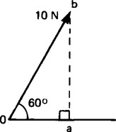
This process is called ‘finding the horizontal and vertical components of a vector’ or ‘the resolution of a vector’, and can be used as an alternative to graphical methods for calculating the resultant of two or more coplanar forces acting at a point.
For example, to calculate the resultant of a 10 N force acting at 60° to the horizontal and a 20 N force acting at − 30° to the horizontal (see Figure 35.9) the procedure is as follows:
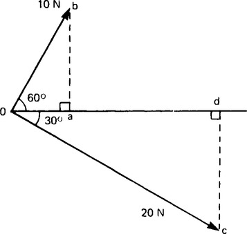
(i) Determine the horizontal and vertical components of the 10 N force, i.e.
horizontal component, oa =10 cos 60°= 5.0 N
vertical component, ab = 10 sin 60°= 8.66 N
(ii) Determine the horizontal and vertical components of the 20 N force, i.e.
horizontal component, od = 20 cos (− 30°) =17.32 N
vertical component, dc = 20 sin (− 30°) = −10.0 N.
(iii) Determine the total horizontal component, i.e.
(iv) Determine the total vertical component, i.e.
ab + cd = 8.66 + (−10.0) = − 1.34 N
(v) Sketch the total horizontal and vertical components as shown in Figure 35.10. The resultant of the two components is given by length or and, by Pythagoras’ theorem,

Hence the resultant of the 10 N and 20 N forces shown in Figure 35.7 is 22.36 N at an angle of − 3° 26 to the horizontal.
The above example demonstrates the use of resolution of forces for calculating the resultant of two coplanar forces acting at a point. However, the method may be used for more than two forces acting at a point.
Summary
(a) To determine the resultant of two coplanar forces acting at a point, there are four methods commonly used. These are, by drawing:
(b) To determine the resultant of more than two coplanar forces acting at a point, there are two methods commonly used. These are, by drawing: