
Simple machines
Publisher Summary
This chapter provides an overview on simple machines. A machine is a device that is capable of changing magnitude or line of action, or both magnitude and line of action of a force. A simple machine usually amplifies an input force, called the effort, to give a larger output force, called the load. Examples of simple machines include pulley systems, screw-jacks, gear systems, and lever systems. The efficiency of a simple machine is defined as the ratio of the force ratio to the movement ratio, whereas its limiting efficiency is defined as the ratio of the limiting force ratio to the movement ratio. Because of the friction and inertia, the limiting efficiency of simple machines is usually well below 100%.
1. A machine is a device which can change the magnitude or line of action, or both magnitude and line of action of a force. A simple machine usually amplifies an input force, called the effort, to give a larger output force, called the load. Some typical examples of simple machines include pulley systems, screw-jacks, gear systems and lever systems.
2. The force ratio or mechanical advantage is defined as the ratio of load to effort, i.e.
Since both load and effort are measured in newtons, force ratio is a ratio of the same units and thus is a dimensionless quantity.
3. The movement ratio or velocity ratio is defined as the ratio of the distance moved by the effort to the distance moved by the load, i.e.
Since the numerator and denominator are both measured in metres, movement ratio is a ratio of the same units and thus is a dimensionless quantity.
(i) The efficiency of a simple machine is defined as the ratio of the force ratio to the movement ratio, i.e.
Since the numerator and denominator are both dimensionless quantities, efficiency is a dimensionless quantity. It is usually expressed as a percentage, thus:
(ii) Due to the effects of friction and inertia associated with the movement of any object, some of the input energy to a machine is converted into heat and losses occur. Since losses occur, the energy output of a machine is less than the energy input, thus the mechanical efficiency of any machine cannot reach 100%. For example, a simple machine raises a load of 160 kg through a distance of 1.6 m. The effort applied to the machine is 200 N and moves through a distance of 16 m.
(iii) For simple machines, the relationship between effort and load is of the form: Fe = aF1 + b, where Fe is the effort, F1 is the load and a and b are constants. From equation (1)
Dividing both numerator and denominator by F1 gives:
When the load is large, F1 is large and b/F1 is small compared with a. The force ratio then becomes approximately equal to 1/a and is called the limiting force ratio.
The limiting efficiency of a simple machine is defined as the ratio of the limiting force ratio to the movement ratio, i.e.

where a is the constant for the law of the machine: Fe = aF1 + b.
Due to friction and inertia, the limiting efficiency of simple machines is usually well below 100%. For example, in a test on a simple machine, the effort-load graph was a straight line of the form Fe = aF1 + b. Two values lying on the graph were at Fe = 10 N, F1 = 30 N and at Fe = 74 N, F1 = 350 N. The movement ratio of the machine was 17.
The equation Fe= aF1 + b is of the form y = mx+c, where m is the gradient of the graph. The slope of the line passing through points (x1, y1) and (x2, y2) of the graph y=mx+c is given by:
Thus for Fe = aF1 + b, the slope a is given by:

5. A pulley system is a simple machine. A single-pulley system, shown in Figure 39.1(a), changes the line of action of the effort, but does not change the magnitude of the force.
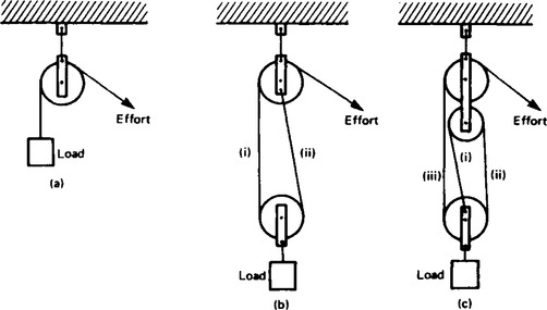
A two-pulley system, shown in Figure 39.1(b), changes both the line of action and the magnitude of the force. Theoretically, each of the ropes marked (i) and (ii) share the load equally, thus the theoretical effort is only half of the load, i.e. the theoretical force ratio is 2. In practice the actual force ratio is less than 2 due to losses.
A three-pulley system is shown in Figure 39.1(c). Each of the ropes marked (i), (ii) and (iii) carry one-third of the load, thus the theoretical force ratio is 3. In general, for a multiple pulley system having a total of n pulleys, the theoretical force ratio is n. Since the theoretical efficiency of a pulley system (neglecting losses) is 100% and since from equation (3):
it follows that when the force ratio is n,
that is the movement ratio is also n.
For example, a load of 80 kg is lifted by a three-pulley system and the applied effort is 392 N.
The movement ratio = 3 (since it is a three-pulley system)
6. A simple screw-jack is shown in Figure 39.2 and is a simple machine since it changes both the magnitude and the line of action of a force.
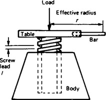
The screw of the table of the jack is located in a fixed nut in the body of the jack. As the table is rotated by means of a bar, it raises or lowers a load placed on the table. For a single-start thread, as shown, for one complete revolution of the table, the effort moves through a distance 2πr and the load moves through a distance equal to the lead of the screw, say I. Thus:
For example, a screw jack is used to support the axle of a car, the load on it being 2.4 kN. The screw jack has an effort arm of effective radius 200 mm and a single-start square thread having a lead of 5 mm. If an effort of 60 N is required to riase the car axle:
(i) A simple gear train is used to transmit rotary motion and can change both the magnitude and the line of action of a force, hence is a simple machine. The gear train shown in Figure 39.3 consists of spur gears and has an effort applied to one gear, called the driver and a load applied to the other gear, called the follower.

(ii) In such a system, the teeth on the wheels are so spaced that they exactly fill the circumference with a whole number of identical teeth, and the teeth on the driver and follower mesh without interference. Under these conditions, the number of teeth on the driver and follower are in direct proportion to the circumference of these wheels, i.e.
 (5)
(5)(iii) If there are, say, 40 teeth on the driver and 20 teeth on the follower then the follower makes two revolutions for each revolution of the driver. In general
 (6)
(6)It follows from equation (6) that the speeds of the wheels in a gear train are inversely proportional to the number of teeth.
(iv) The ratio of the speed of the driver wheel to that of the follower is the movement ratio, i.e.
(v) When the same direction of rotation is required on both the driver and the follower an idler wheel is used as shown in Figure 39.4. Let the driver, idler and follower be A, B and C respectively, and let N be the speed of rotation and T be the number of teeth. Then from equation (7),


This shows that the movement ratio is independent of the idler, only the direction of the follower being altered.
(vi) A compound gear train is shown in Figure 39.5, in which gear wheels B and C are fixed to the same shaft and hence NB = NC. From equation (7),

 (8)
(8)For compound gear trains having say P gear wheels,
For example, a compound gear train consists of a driver gear A having 40 teeth, engaging with gear B, having 160 teeth. Attached to the same shaft as B, gear C has 48 teeth and meshes with gear D on the output shaft having 96 teeth.
Thus from equation (8),

If the force ratio is, say, 6, then the efficiency is ![]() × 100% = 75%.
× 100% = 75%.
8. A lever can alter both the magnitude and the line of action of a force and is thus classed as a simple machine. There are three types or orders of levers, as shown in Figure 39.6.
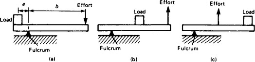
(i) A lever of the first order has the fulcrum placed between the effort and the load, as shown in Figure 39.6(a).
(ii) A lever of the second order has the load placed between the effort and fulcrum, as shown in Figure 39.6(b).
(iii) A lever of the third order has the effort applied between the load and the fulcrum, as shown in Figure 39.6(c).
Problems on levers can largely be solved by applying the principle of moments (see page 279). Thus for the lever shown in Figure 39.6(a), when the lever is in equilibrium
anticlockwise moment=clockwise moment
For example, the load on a first-order lever is 1.2 kN, the distance between the fulcrum and load is 0.5 m and the distance between the fulcrum and effort is 1.5 m. Thus, at equilibrium,
anticlockwise moment=clockwise moment
i.e. 1200 × 0.5 = effort × 1.5
This result shows that to lift a load of say 300 N, an effort of 100 N is required.