
Measurement of fluid flow
Publisher Summary
This chapter discusses the measurement of fluid flow. Fluid flow is one of the most difficult of the industrial measurements to carry out, as the flow behavior depends on a great many variables concerning the physical properties of a fluid. There are available a large number of fluid flow measuring instruments, generally called flow meters that can measure the flow rate of liquids or the mass flow rate of gaseous fluids (in kg/s). The two main categories of flow meters are differential pressure flow meters and mechanical flow meters. The flow rate of the fluid can also be determined from a measurement of the difference between the pressures on the walls of the pipe at specified distances upstream and downstream of the flow meter. Such devices are known as differential pressure flow meters. Examples of differential pressure flow meters commonly used include: orifice plate, venturi tube, flow nozzles, and pitot-static tube.
1. The measurement of fluid flow is of great importance in many industrial processes, some examples including air flow in the ventilating ducts of a coal mine, the flow rate of water in a condenser at a power station, the flow rate of liquids in chemical processes, the control and monitoring of the fuel, lubricating and cooling fluids of ships and aircraft engines, and so on.
Fluid flow is one of the most difficult of industrial measurements to carry out, since flow behaviour depends on a great many variables concerning the physical properties of a fluid.
2. There are available a large number of fluid flow measuring instruments, generally called flow meters, which can measure the flow rate of liquids (in m3/s) or the mass flow rate of gaseous fluids (in kg/s). The two main categories of flow meters are differential pressure flow meters and mechanical flow meters.
(i) When certain flow meters are installed in pipelines they often cause an obstruction to the fluid flowing in the pipe by reducing the cross-sectional area of the pipeline. This causes a change in the velocity of the fluid, with a related change in pressure. Figure 49.1 shows a section through a pipeline into which a flow meter has been inserted. The flow rate of the fluid may be determined from a measurement of the difference between the pressures on the walls of the pipe at specified distances upstream and downstream of the flowmeter. Such devices are known as differential pressure flow meters.
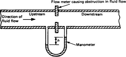
(ii) The pressure in Figure 49.1 is measured using a manometer connected to appropriate pressure tapping points. The pressure is seen to be greater upstream of the flow meter than downstream, the pressure difference being shown as h. Calibration of the manometer depends on the shape of the obstruction, the positions of the pressure tapping points and the physical properties of the fluid.
(iii) Examples of differential pressure flow meters commonly used include:
(a) Orifice plate (see para. 6).
(b) Venturi tube (see para. 7),
(c) Flow nozzles (see para. 8), and
(d) Pitot-static tube (see para. 9).
(iv) British standard reference BS 1042: Part 1: 1964 and Part 2A: 1973 ‘Methods for the measurement of fluid flow in pipes’ give specifications for measurement, manufacture, tolerances, accuracy, sizes, choice, and so on, of differential flow meters.
(i) With mechanised flow meters a sensing element situated in a pipeline is displaced by the fluid flowing past it.
(ii) Examples of mechanical flow meters commonly used include:
5. Other flow meters available include:
(a) Float and tapered-tube meter (see para. 12),
(b) Electromagnetic flow meter (see para. 13), and
Orifice plate
(a) An orifice plate consists of a circular, thin, flat plate with a hole (or orifice) machined through its centre to fine limits of accuracy. The orifice has a diameter less than the pipeline into which the plate is installed and a typical section of an installation is shown in Figure 49.1(a), Orifice plates are manufactured in stainless steel, monel metal, polyester glass fibre, and for large pipes, such as sewers or hot gas mains, in brick and concrete.
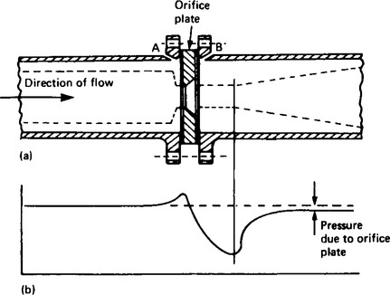
When a fluid moves through a restriction in a pipe, the fluid accelerates and a reduction in pressure occurs, the magnitude of which is related to the flow rate of the fluid. The variation of pressure near an orifice plate is shown in Figure 49.2(b) The position of minimum pressure is located downstream from the orifice plate where the flow stream is narrowest. This point of minimum cross-sectional area of the jet is called the ‘vena contracts’. Beyond this point the pressure rises but does not return to the original upstream value and there is a permanent pressure loss. This loss depends on the size and type of orifice plate, the positions of the upstream and downstream pressure tappings and the change in fluid velocity between the pressure tappings which depends on the flow rate and the dimensions of the orifice plate.
In Figure 49.2(a) corner pressure tappings are shown at A and B. Alternatively, with an orifice plate inserted into a pipeline of diameter d, pressure tappings are often located at distances of d and d/2 from the plate respectively upstream and downstream. At distance d upstream the flow pattern is not influenced by the presence of the orifice plate and distance d/2 coincides with the vena contracta.
(b) Advantages of orifice plates are:
(i) they are relatively inexpensive; and
(ii) they are usually thin enough to fit between an existing pair of pipe flanges.
(c) Disadvantages of orifice plates are:
(i) the sharpness of the edge of the orifice can become worn with use, causing calibration errors;
(ii) the possible build-up of matter against the plate; and
(iii) a considerable loss in the pumping efficiency due to the pressure loss downstream of the plate.
Orifice plates are usually used in medium and large pipes and are best suited to the indication and control of essentially constant flow rates. Several applications are found in the general process industries.
Venturi tube
Construction
(a) The Venturi tube or venturimeter is an instrument for measuring with accuracy the flow rate of fluids in pipes. A typical arrangement of a section through such a device is shown in Figure 49.3, and consists of a short converging conical tube called the inlet or upstream cone leading to a cylindrical portion called the throat. This is followed by a diverging section called the outlet or recovery cone. The entrance and exit diameter is the same as that of the pipeline into which it is installed. Angle β is usually a maximum of 21°, giving a taper of β/2 of 10. The length of the throat is made equal to the diameter of the throat. Angle α is about 5° to 7° to ensure a minimum loss of energy but where this is unimportant α can be as large as 14° or 15°.
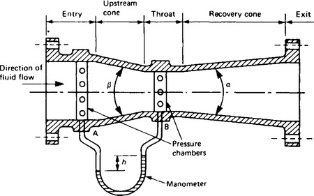
Pressure tappings are made at the entry (at A) and at the throat (at B) and the pressure difference h which is measured using a manometer or similar gauge, is dependant on the flow rate through the meter. Usually pressure chambers are fitted around the entrance pipe and the throat circumference with a series of tapping holes made in the chamber to which the manometer is connected. This ensures an average pressure is recorded. The loss of energy due to turbulence which occurs just downstream with an orifice plate is largely avoided in the venturimeter due to the gradual divergence beyond the throat.
Venturimeters are usually made a permanent installation in a pipeline and are usually manufactured from stainless steel, cast iron, monel metal or polyester glass fibre.
Flow nozzles
8. The flow nozzle lies between the orifice plate and the venturimeter both in performance and cost. A typical section through a flow nozzle is shown in Figure 49.4 where pressure tappings are located immediately adjacent to the upstream and downstream faces of the nozzle (i.e. at points A and B). The fluid does not contract any further as it leaves the nozzle and the pressure loss created is considerably less than that occurring with orifice plates.
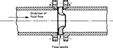
Flow nozzles are suitable for use with high velocity flows for they do not suffer the wear that occurs in orifice plate edges during such flows.
Pitot-static tube
(a) A Pitot-static tube is a device for measuring the velocity of moving fluids or of the velocity of bodies moving through fluids. It consists of one tube, called the Pitot tube, with an open end facing the direction of the fluid motion, shown as pipe R in Figure 49.5 and a second tube, called the static tube, with the opening at 90° to the fluid flow, shown as T in Figure 49.5 Pressure is recorded by a pressure gauge moving with the flow, i.e. static or stationary relative to the fluid. This is called static pressure and connecting a pressure gauge to a small hole in the wall of a pipe, such as point T in Figure 49.5, is the easiest method of recording this pressure. The difference in pressure (pR – pT), shown as h in the manometer of Figure 49.5 is an indication of the speed of the fluid in the pipe.
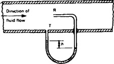
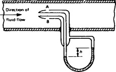
Figure 49.6 shows a practical Pitot-static tube consisting of a pair of concentric tubes. The centre tube is the impact probe which has an open end which faces ‘head-on’ into the flow. The outer tube has a series of holes around its circumference located at right angles to the flow – as seen by AB in Figure 49.6 The manometer, showing a pressure difference of h, may be calibrated to indicate the velocity of flow directly.
Applications
(b) A Pitot-static tube may be used for both turbulent and non-turbulent flow. The tubes canbe made very small compared with the size of the pipeline and the monitoring of flow velocity at particular points in the cross-section of a duct can be achieved. The device is generally unsuitable for routine measurements and in industry is often used for making preliminary tests of flow rate in order to specify permanent flow measuring equipment for a pipeline. Another use is the measurement of ventilating-duct air flows in mines.
However, the main use of Pitot tubes is to measure the velocity of solid bodies moving through fluids, such as the velocity of ships and of low speed aircraft. In these cases, the tube is connected to a Bourdon pressure gauge which can be calibrated to read velocity directly. A development of the Pitot tube, a pitometer, tests the flow of water in water mains and detects leakages.
Deflecting vane flow meter
10. The deflecting vane flow meter consists basically of a pivoted vane suspended in the fluid flow stream as shown in Figure 49.7
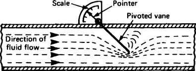
When a jet of fluid impinges on the vane it deflects from its normal position by an amount proportional to the flow rate. The movement of the vane is indicated on a scale which may be calibrated in flow units. This type of meter is normally used for measuring liquid flow rates in open channels or for measuring the velocity of air in ventilation ducts. The main disadvantages of this device are that it restricts the flow rate and it needs to be recalibrated for fluids or differing densities.
Turbine type flow meters
11. Turbine type flow meters are those which use some form of multi-vane rotor and are driven by the fluid being investigated. Three such devices are the cup anemometer, the rotary vane positive displacement meter and the turbine flow meter.
Cup anemometer
(a) An anemometer is an instrument which measures the velocity of moving gases and is most often used for the measurement of wind speed. The cup anemometer has 3 or 4 cups of hemispherical shape mounted at the end of arms radiating horizontally from a fixed point. The cup system spins round the vertical axis with a speed approximately proportional to the velocity of the wind. With the aid of a mechanical and/or electrical counter the wind speed can be determined and the device is easily adapted for automatic recording.
(b) Rotary vane positive displacement meters measure the flow rate by indicating the quantity of liquid flowing through the meter in a given time. A typical device is shown in section in Figure 49.8 and consists of a cylindrical chamber into which is placed a rotor containing a number of vanes (six in this case). Liquid entering the chamber turns the rotor and a known amount of liquid is trapped and carried round to the outlet.
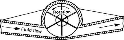
If x is the volume displaced by one blade then for each revolution of the rotor in Figure 49.8, the total volume displaced is 6x. The rotor shaft may be coupled to a mechanical counter and electrical devices which may be calibrated to give flow volume. This type of meter in its various forms is widely used for the measurement of domestic and industrial water consumption, for the accurate measurement of petrol in petrol pumps and for the consumption and batch control measurements in the general process and food industries for measuring flows as varied as solvents, tar and mollases (i.e. thickish treacle).
(c) A turbine flow meter contains in its construction a rotor to which blades are attached which spin at a velocity proportional to the velocity of the fluid which flows through the meter. A typical section through such a meter is shown in Figure 49.9 The number of revolutions made by the turbine blades may be determined by a mechanical or electrical device enabling the flow rate or total flow to be determined.
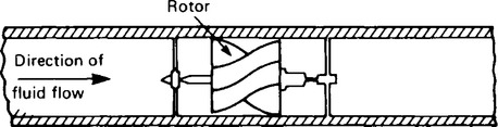
Advantages of turbine flow meters include a compact durable form, high accuracy, wide temperature and pressure capability and good response characteristics. Applications include the volumetric measurement of both crude and refined petroleum products in pipelines up to 600 mm bore, and in the water, power, aerospace, process and food industries, and with modification may be used for natural, industrial and liquid gas measurements. Turbine flow meters require periodic inspection and cleaning of the working parts.
Float and tapered-tube flow meter
Construction
(a) With orifice plates and venturimeters the area of the opening in the obstruction is fixed and any change in the flow rate produces a corresponding change in pressure. With the float and tapered tube meter the areaof the restriction may be varied so as to maintain a steady pressure differential. A typical meter of this is shown diagrammatically in Figure 49.10 where a vertical tapered tube contains a ‘float’ which has adensity greater than the fluid.
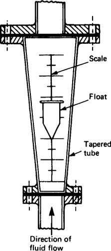
The float in the tapered tube produces a restrictionto the fluid flow. The fluid can only pass in the annular area between the float and the walls of the tube. This reductionin area produces an increase in velocity and hence a pressuredifference, which causes the float to rise. The greater the flow rate, the greater is the rise in the float position, and vice-versa.
The position of the float is a measure of the flow rate of the fluid and this is shown on a vertical scale engraved on a transparent tube of plastic or glass. For air, a small sphere is used for the float but for liquids there is a tendency to instability and the float is then designed with vanes which cause it to spin and thus stabilise itself as the liquid flows past. Such meters are often called ‘rotameters’. Calibration of float and tapered tube flow meters can be achieved using a Pitot-static tube or by installing an orifice plate or venturimeter in the pipeline.
(b) Advantages of float and tapered tube flow meters:
(c) Disadvantages of float and tapered tube flow meters:
(i) They are prone to errors, such as those caused by temperature fluctuations;
(ii) They can only be installed vertically in a pipeline;
(iii) They cannot be used with liquids containing large amounts of solids in suspension;
(iv) They need to be recalibrated for fluids of differentdensities.
(d) Practical applications of float and tapered tube meters are found in the medical field, in instrument purging, in mechanical engineering test rigs and in simple process applications, in particular for very low flow rates. Many corrosive fluids can be handled with this device without complications.
Electromagnetic flow meter
(a) The flow rate of fluids which conduct electricity, such as water or molten metal, can be measured using an electromagnetic flow meter whose principle of operation is based onthe laws of electromagnetic induction. When a conductor of length l moves at right angles to a magnetic field of density B at a velocityof v, an induced e.m.f. e is generated, given by e =Blv (see Chapter 11).
With the electromagnetic flow meter arrangement shown in Figure 49.11, the fluid is the conductor and the e.m.f. is detected by two electrodes placed across the diameter of the non-magnetic tube. Rearranging e = Blv gives
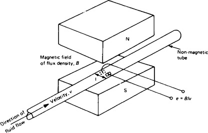
Thus with B and l known, when e is measured, the velocity of the fluid can be calculated.
(b) Main advantages of electromagnetic flowmeters:
(i) Unlike other methods, there is nothing to directly impede the fluid flow;
(ii) There is a linear relationship between the fluid flow and the induced e.m.f.;
(iii) Flow can be metered in either direction by using a centre zero measuring instrument.
(c) Applications of electromagnetic flow meters are found in the measurement of speeds of slurries, pastes and viscous liquids, and are also widely used in the water production, supply and treatment industry.
Hot-wire anemometer
(a) A simple hot wire anemometer consists of a small piece of wire which is heated by an electric current and positioned in the air or gas stream whose velocity is to be measured. The stream passing the wire tends to cool it, the rate of cooling being dependant on the flow velocity. There are various ways in which this is achieved:
(i) If a constant current is passed through the wire variation in flow results in a change of temperature of the wire and hence a change in resistance which may be measured by a Wheatstone bridge arrangement. The change in resistance may be related to fluid flow.
(ii) If the Wire’s resistance, and hence temperature, is kept constant, a change in fluid flow results in a corresponding change in current which can be calibrated as an indication of the flow rate.
(iii) A thermocouple may be incorporated in the assembly monitoring the hot wire and recording the temperature which indicates the air or gas velocity.