
]>
Appendix 1D: Low-Frequency Approximation of Maxwell’s Equations R, L, C, and Memristor M
1D.1Introduction
Circuit theory, used extensively in low-frequency electrical engineering, is a low-frequency approximation of Maxwell’s equations. It is formulated in terms of the two-terminal circuit elements such as resistance (R), inductance (L), and capacitance (C). Fano et al. [1] discussed circuit theory as a quasistatic approximation in terms of the time-rate parameter α, which was used to expand the electromagnetic fields in power series. The classical elements R, L, and C were shown to be obtained by certain combinations of the zeroth- and first-order solutions. Chua [2] pointed out that a new circuit element M, called memristor (memory + resistor), could be proposed based on the relationship between the charge q(t) and the magnetic flux Φm(t). Such a two-terminal element realized recently [3] has interesting properties and applications.
1D.2Time-Rate Parameter
In preparing for generating quasistatic solutions, let us first consider the family of solutions generated by changing the timescale of the excitation. As an example, suppose the excitation is ρ(x, y, z, t), consider the family of solutions obtained by the excitation ρ(x, y, z, αt), where α is called the time-rate parameter. We can rewrite Maxwell’s equations in terms of the variable
Then
Maxwell’s equations (1.1), equations (1.2), equations (1.3) and equations (1.5) can now be written as
and Equation 1.5 becomes
Since the fields are functions of , and the parameter α, they can be expressed in power series in terms of α as
where
If we use similar power-series expressions and use in Equation 1D.3, Equation 1D.4, Equation 1D.5, Equation 1D.6 and Equation 1D.7 and collect terms to the same power of α, for instance, then we obtain
Similar equations can be obtained, based on Equation 1D.4, Equation 1D.5, Equation 1D.6, Equation 1D.7, Equation 1D.8 and Equation 1D.9.
Equation 1D.9 must be satisfied, for all values of α. This can be met only if the coefficients of all the powers of α are separately equal to zero. Thus, we obtain the series of equations
We can generate higher-order sets of equations such as Equation 1D.13, Equation 1D.14 and Equation 1D.15. Note, however, from Equations 1D.5 and 1D.6, we obtain
1D.3Circuit Parameters R, L, and C
The circuit element R is identified as the zeroth-order solution of Equations 1D.10 and 1D.11. For a resistor R, the first-order electric and magnetic fields are negligible compared with the zeroth-order fields. Its characterization as a relationship between the zeroth-order electric and magnetic fields leads to the memoryless instantaneous relationship of a pure resistor. Its gross parameter representation is Ohm’s law given by
If only the first-order magnetic field is negligible but the first-order electric field is not negligible, the system can be identified as a resistor in series with an inductor [2]. Its gross parameter representation is
On the other hand, if only the first-order electric field is negligible but the first-order magnetic field is not negligible, the system can be identified as a resistor R (conductance G = 1/R) in parallel with a capacitor C. The gross parameter representation in this case is
Equations 1D.19 and 1D.20 can be obtained and R, G, L, and C are calculated by using the integral form of the relevant Maxwell’s equations and the constitutive relations for the material:
1D.4Memristor
Fano et al. [1] dismissed the case where the first-order fields and are not negligible saying that such a case is not relevant to circuit theory. Chua [2] suggested that such a case under approximate conditions leads to a two-terminal device where the charge q(t) (the surface integral of the first-order electric flux density vector ) is related to the flux Φm(t) (surface integral of the first-order field). The approximate conditions are: (i) both zeroth-order fields are negligible compared to the first-order fields; and (ii) the material of the device is nonlinear.
The nonlinear relationships are
leading to
Equation 1D.29 gives the instantaneous (memoryless) relationship between and .
A physical memristor device is essentially an ac device; otherwise, the dc electromagnetic fields will give rise to nonnegligible zeroth-order fields.
In terms of gross variables and parameters we write
In the case of a memristor
For the case of a charge-controlled memristor
where
is the incremental memristance (in the units of ohms).
The mathematical model for the HP memristor [3,4] which is based on its fabrication process is given by
where
Here, μD is the average drift mobility and D is the film (titanium dioxide) thickness. ROFF and RON are the “OFF” and “ON” states of the resistance. The device is a TiO2 junction where one side is doped with positive ions and the other side is undoped. The width w of the doped region depends on the charge passing through the device. The state equation describing process can be written as
where
Figure 1D.1 gives the symbol proposed in [1] and q versus Φm curve for the memristor.
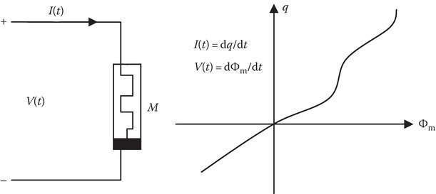
FIGURE 1D.1
Memristor and its Φm versus q curve.
Memristor is a passive two-terminal device. It cannot store energy, when V(t) = 0 and I(t) = 0. A memristor acts as a linear resistor when its frequency goes toward infinity and as a nonlinear resistor at low frequencies.
It has a regime of operation with an approximately linear charge–resistance relationship as the time integral of the current stays within certain bounds. Applications are in nanoelectronic memories, computer logic, and neuromorphic computer architectures.
In an ideal description, the element remembers the amount of current passing through it in the past. When the current stops, the component retains the last resistance that it had. When the flow of charge starts again, the resistance of the circuit will be what it was when it was last active.
In summary, unlike the resistor R whose value depends on the ratio of instantaneous voltage to current, in the case of memristor the resistance depends on the ratio of the integral of the input voltage to the integral of the input current.
Since ∫V dt = Φm and ∫I dt = q, it is the functional relationship between Φm and q that determines the properties of the memristor. If this relationship is linear, it is the same as the resistor R.
This is an active field of research with many potential applications and developments.
References
- 1.Fano, R. M., Chu, L. N., and Adler, R. B., Electromagnetic Fields, Energy, and Forces, Wiley, New York, 1960.
- 2.Chua, L. O., Memristor, the missing circuit element, IEEE Trans. Circ. Theory, CT-18(5), 507–519, 1971.
- 3.Strukov, D. B., Snider, G. S., Steward, D. R., and Williams, R. S., The missing memristor found, Nature, 453(7191), 80–83, 2008.
- 4.Kavehei, O., Iqbal, A., Kim, Y. S., Eshraghiam, K., Al-Sarawi, S. F., and Abbott, D., The fourth element: Characteristics, modeling and electromagnetic theory of the memristor, Proc. R. Soc. A, 466(2120), 2175–2202, 2010.