 Appendix 2B: Transmission Lines: Power Calculation
by Dikshitulu K. Kalluri
Principles of Electromagnetic Waves and Materials, 2nd Edition
Appendix 2B: Transmission Lines: Power Calculation
by Dikshitulu K. Kalluri
Principles of Electromagnetic Waves and Materials, 2nd Edition
- Cover
- Halftitle Page
- Title Page
- Copyright Page
- Contents
- Preface
- Acknowledgments
- Author
- Selected List of Symbols
- List of Book Sources
- Part I Electromagnetics of Bounded Simple Media
- 1. Electromagnetics of Simple Media
- 2. Electromagnetics of Simple Media: One-Dimensional Solution
- 2.1 Uniform Plane Waves in Sourceless Medium (ρV = 0, Jsource = 0)
- 2.2 Good Conductor Approximation
- 2.3 Uniform Plane Wave in a Good Conductor: Skin Effect
- 2.4 Boundary Conditions at the Interface of a Perfect Electric Conductor with a Dielectric
- 2.5 AC Resistance
- 2.6 AC Resistance of Round Wires
- 2.7 Voltage and Current Harmonic Waves: Transmission Lines
- 2.8 Bounded Transmission Line
- 2.9 Electromagnetic Wave Polarization
- 2.10 Arbitrary Direction of Propagation
- 2.11 Wave Reflection
- 2.12 Incidence of p Wave: Parallel-Polarized
- 2.13 Incidence of s Wave: Perpendicular-Polarized
- 2.14 Critical Angle and Surface Wave
- 2.15 One-Dimensional Cylindrical Wave and Bessel Functions
- References
- 3. Two-Dimensional Problems and Waveguides
- 3.1 Two-Dimensional Solutions in Cartesian Coordinates
- 3.2 TMmn Modes in a Rectangular Waveguide
- 3.3 TEmn Modes in a Rectangular Waveguide
- 3.4 Dominant Mode in a Rectangular Waveguide: TE10 Mode
- 3.5 Power Flow in a Waveguide: TE10 Mode
- 3.6 Attenuation of TE10 Mode due to Imperfect Conductors and Dielectric Medium
- 3.7 Cylindrical Waveguide: TM Modes
- 3.8 Cylindrical Waveguide: TE Modes
- 3.9 Sector Waveguide
- 3.10 Dielectric Cylindrical Waveguide: Optical Fiber
- References
- 4. Three-Dimensional Solutions
- 5. Spherical Waves and Applications
- 6. Laplace Equation: Static and Low-Frequency Approximations
- 7. Miscellaneous Topics on Waves
- Part II Electromagnetic Equations of Complex Media
- 8. Electromagnetic Modeling of Complex Materials
- 8.1 Volume of Electric Dipoles
- 8.2 Frequency-Dependent Dielectric Constant
- 8.3 Modeling of Metals
- 8.4 Plasma Medium
- 8.5 Polarizability of Dielectrics
- 8.6 Mixing Formula
- 8.7 Good Conductors and Semiconductors
- 8.8 Perfect Conductors and Superconductors
- 8.9 Magnetic Materials
- 8.10 Chiral Medium
- 8.11 Plasmonics and Metamaterials
- References
- 9. Waves in Isotropic Cold Plasma: Dispersive Medium
- 9.1 Basic Equations
- 9.2 Dielectric–Dielectric Spatial Boundary
- 9.3 Reflection by a Plasma Half-Space
- 9.4 Reflection by a Plasma Slab
- 9.5 Tunneling of Power through a Plasma Slab
- 9.6 Inhomogeneous Slab Problem
- 9.7 Periodic Layers of Plasma
- 9.8 Surface Waves
- 9.9 Transient Response of a Plasma Half-Space
- 9.10 Solitons
- 9.11 Perfect Dispersive Medium
- References
- 10. Spatial Dispersion and Warm Plasma
- 10.1 Waves in a Compressible Gas
- 10.2 Waves in Warm Plasma
- 10.3 Constitutive Relation for a Lossy Warm Plasma
- 10.4 Dielectric Model of Warm Loss-Free Plasma
- 10.5 Conductor Model of Warm Lossy Plasma
- 10.6 Spatial Dispersion and Nonlocal Metal Optics
- 10.7 Technical Definition of Plasma State
- References
- 11. Wave in Anisotropic Media and Magnetoplasma
- 11.1 Introduction
- 11.2 Basic Field Equations for a Cold Anisotropic Plasma Medium
- 11.3 One-Dimensional Equations: Longitudinal Propagation and L and R Waves
- 11.4 One-Dimensional Equations: Transverse Propagation—O Wave
- 11.5 One-Dimensional Solution: Transverse Propagation—X Wave
- 11.6 Dielectric Tensor of a Lossy Magnetoplasma Medium
- 11.7 Periodic Layers of Magnetoplasma
- 11.8 Surface Magnetoplasmons
- 11.9 Surface Magnetoplasmons in Periodic Media
- 11.10 Permeability Tensor
- 11.11 Reflection by a Warm Magnetoplasma Slab
- References
- 12. Optical Waves in Anisotropic Crystals
- 13. Time-Domain Solutions
- 13.1 Introduction
- 13.2 Transients on Bounded Ideal Transmission Lines
- 13.3 Transients on Lossy Transmission Lines
- 13.4 Direct Solution in Time Domain: Klein–Gordon Equation
- 13.5 Nonlinear Transmission Line Equations and KdV Equation
- 13.6 Charged Particle Dynamics
- 13.6.1 Introduction
- 13.6.2 Kinematics
- 13.6.3 Conservation of Particle Energy due to Stationary Electric and Magnetic Fields
- 13.6.4 Constant Electric and Magnetic Fields
- 13.6.5 Constant Gravitational Field and Magnetic Field
- 13.6.6 Drift Velocity in Nonuniform B Field
- 13.6.7 Time-Varying Fields and Adiabatic Invariants
- 13.6.8 Lagrange and Hamiltonian Formulations of Equations of Motion
- 13.7 Nuclear Electromagnetic Pulse and Time-Varying Conducting Medium
- 13.8 Magnetohydrodynamics (MHD)
- 13.9 Time-Varying Electromagnetic Medium
- 13.9.1 Frequency Change due to a Temporal Discontinuity in the Medium Properties
- 13.9.2 Effect of Switching an Unbounded Isotropic Plasma Medium
- 13.9.3 Sudden Creation of a Plasma Slab
- 13.9.4 Time-Varying Magnetoplasma Medium
- 13.9.5 Modeling of Building Up Plasma versus Collapsing Plasma
- 13.9.6 Applications
- 13.9.7 Subcycle Time-Varying Medium
- 13.9.8 Periodically Time-Varying Parameter, Mathieu Equation, and Parametric Resonance
- 13.10 Statistical Mechanics and Boltzmann Equation
- References
- 14. Electromagnetics of Moving Media: Uniform Motion
- 14.1 Introduction
- 14.2 Snell’s Law
- 14.3 Galilean Transformation
- 14.4 Lorentz Transformation
- 14.5 Lorentz Scalars, Vectors, and Tensors
- 14.6 Electromagnetic Equations in Four-Dimensional Space
- 14.7 Lorentz Transformation of the Electromagnetic Fields
- 14.8 Frequency Transformation and Phase Invariance
- 14.9 Reflection from a Moving Medium
- 14.10 Constitutive Relations for a Moving Dielectric
- 14.11 Relativistic Particle Dynamics
- 14.12 Transformation of Plasma Parameters
- 14.13 Reflection by a Moving Plasma Slab
- 14.14 Brewster Angle and Critical Angle for Moving Plasma Medium
- 14.15 Bounded Plasmas Moving Perpendicular to the Plane of Incidence
- 14.16 Waveguide Modes of Moving Plasmas
- 14.17 Impulse Response of a Moving Plasma Medium
- 14.18 First-Order Lorentz Transformation
- 14.19 Alternate Form of Position Four-Vector
- References
- 8. Electromagnetic Modeling of Complex Materials
- Part III Appendices
- Appendix 1A: Vector Formulas and Coordinate Systems
- Appendix 1B: Retarded Potentials and Review of Potentials for the Static Cases
- Appendix 1C: Poynting Theorem
- Appendix 1D: Low-Frequency Approximation of Maxwell’s Equations R, L, C, and Memristor M
- Appendix 2A: AC Resistance of a Round Wire When the Skin Depth δ Is Comparable to the Radius a of the Wire
- Appendix 2B: Transmission Lines: Power Calculation
- Appendix 2C: Introduction to the Smith Chart
- Appendix 2D: Nonuniform Transmission Lines
- Appendix 4A: Calculation of Losses in a Good Conductor at High Frequencies: Surface Resistance RS
- Appendix 6A: On Restricted Fourier Series Expansion
- Appendix 7A: Two- and Three-Dimensional Green’s Functions
- Appendix 8A: Wave Propagation in Chiral Media
- Appendix 8B: Left-Handed Materials and Transmission Line Analogies
- Appendix 9A: Backscatter from a Plasma Plume due to Excitation of Surface Waves
- Appendix 10A: Thin Film Reflection Properties of a Warm Isotropic Plasma Slab between Two Half-Space Dielectric Media
- Appendix 10B: First-Order Coupled Differential Equations for Waves in Inhomogeneous Warm Magnetoplasmas
- Appendix 10C: Waveguide Modes of a Warm Drifting Uniaxial Electron Plasma
- Appendix 11A: Faraday Rotation versus Natural Rotation
- Appendix 11B: Ferrites and Permeability Tensor
- Appendix 11C: Thin Film Reflection Properties of a Warm Magnetoplasma Slab: Coupling of Electromagnetic Wave with Electron Plasma Wave
- Appendix 13A: Maxwell Stress Tensor and Electromagnetic Momentum Density
- Appendix 13B: Electric and Magnetic Forces and Newton’s Third Law
- Appendix 13C: Frequency and Polarization Transformer (10–1000 GHz): Interaction of a Whistler Wave with a Collapsing Plasma in a Cavity
- Appendix 14A: Electromagnetic Wave Interaction with Moving Bounded Plasmas
- Appendix 14B: Radiation Pressure Due to Plane Electromagnetic Waves Obliquely Incident on Moving Media
- Appendix 14C: Reflection and Transmission of Electromagnetic Waves Obliquely Incident on a Relativistically Moving Uniaxial Plasma Slab
- Appendix 14D: Brewster Angle for a Plasma Medium Moving at a Relativistic Speed
- Appendix 14E: On Total Reflection of Electromagnetic Waves from Moving Plasmas
- Appendix 14F: Interaction of Electromagnetic Waves with Bounded Plasmas Moving Perpendicular to the Plane of Incidence
- Appendix 14G: Moving Point Charge and Lienard–Wiechert Potentials
- Part IV Chapter Problems
- Index
]>
Appendix 2B: Transmission Lines: Power Calculation
2B.1Transmission Lines: Power Calculation
A transmission line of length d is shown in Figure 2B.1a. The equivalent circuit is shown in Figure 2B.1b.
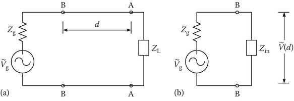
FIGURE 2B.1
Transmission line: (a) length d and (b) equivalent input impedance.
The input impedance into the transmission line of length d with load ZL is given by
The voltage at the input of the transmission line can be found as
where
In the above,
The average incident power is given as
The average reflected power is given by
The total power consumed by the load is
This is shown in Figure 2B.2.
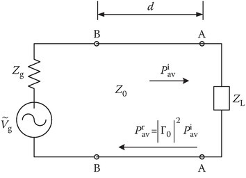
FIGURE 2B.2
Transmission line circuit showing incident and reflected power.
2B.2Transmission Lines: Special Case Zg = Z0
Consider the special case of the transmission line circuit in Figure 2B.1a with Zg = Z0, the characteristic impedance of the transmission line. It will be shown that
Substituting Equations 2B.1 and 2B.9 in the expression for
Rearranging,
which holds whenever Zg = Z0 regardless of the value of ZL.
-
No Comment