
8.6 Design Example: Video Accelerator
In this section we consider the design of a video accelerator, specifically a motion estimation accelerator. Digital video is still a computationally intensive task, so it is well suited to acceleration. Motion estimation engines are used in real-time search engines; we may want to have one attached to our personal computer to experiment with video processing techniques.
8.6.1 Video Compression
Before examining the video accelerator itself, let’s look at video compression algorithms in order to understand the role played by a motion estimation engine.
Figure 8.29 shows the block diagram for MPEG-2 video compression [Has97]. MPEG-2 forms the basis for U.S. HDTV broadcasting. This compression uses several component algorithms together in a feedback loop. The discrete cosine transform (DCT) used in JPEG also plays a key role in MPEG-2. As in still image compression, the DCT of a block of pixels is quantized for lossy compression and then subjected to lossless variable-length coding to further reduce the number of bits required to represent the block.
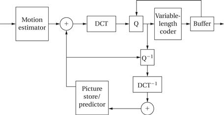
Figure 8.29 Block diagram of MPEG-2 compression algorithm.
Motion-based coding
However, JPEG-style compression alone does not reduce video bandwidth enough for many applications. MPEG uses motion to encode one frame in terms of another. Rather than send each frame separately, as in motion JPEG, some frames are sent as modified forms of other frames using a technique known as block motion estimation. During encoding, the frame is divided into macroblocks. Macroblocks from one frame are identified in other frames using correlation. The frame can then be encoded using the vector that describes the motion of the macroblock from one frame to another without explicitly transmitting all of the pixels. As shown in Figure 8.29, the MPEG-2 encoder also uses a feedback loop to further improve image quality. This form of coding is lossy and several different conditions can cause prediction to be imperfect: objects within a macroblock may move from one frame to the next, a macroblock may not be found by the search algorithm, etc. The encoder uses the encoding information to recreate the lossily-encoded picture, compares it to the original frame, and generates an error signal that can be used by the receiver to fix smaller errors. The decoder must keep some recently decoded frames in memory so that it can retrieve the pixel values of macroblocks. This internal memory saves a great deal of transmission and storage bandwidth.
The concept of block motion estimation is illustrated in Figure 8.30. The goal is to perform a two-dimensional correlation to find the best match between regions in the two frames. We divide the current frame into 16 × 16 macroblocks. For every macroblock in the frame, we want to find the region in the previous frame that most closely matches the macroblock. Searching over the entire previous frame would be too expensive, so we usually limit the search to a given area, centered around the macroblock and larger than the macroblock. We try the macroblock at various offsets in the search area. We measure similarity using the following sum-of-differences measure:
![]() (Eq. 8.3)
(Eq. 8.3)
where M(i,j) is the intensity of the macroblock at pixel i,j, S(i,j) is the intensity of the search region, n is the size of the macroblock in one dimension, and ![]() Gox, oyH is the offset between the macroblock and search region. Intensity is measured as an 8-bit luminance that represents a monochrome pixel—color information is not used in motion estimation. We choose the macroblock position relative to the search area that gives us the smallest value for this metric. The offset at this chosen position describes a vector from the search area center to the macroblock’s center that is called the motion vector.
Gox, oyH is the offset between the macroblock and search region. Intensity is measured as an 8-bit luminance that represents a monochrome pixel—color information is not used in motion estimation. We choose the macroblock position relative to the search area that gives us the smallest value for this metric. The offset at this chosen position describes a vector from the search area center to the macroblock’s center that is called the motion vector.
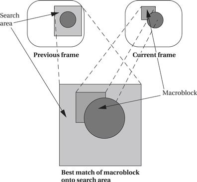
Figure 8.30 Block motion estimation.
8.6.2 Algorithm and Requirements
For simplicity, we will build an engine for a full search, which compares the macroblock and search area at every possible point. Because this is an expensive operation, a number of methods have been proposed for conducting a sparser search of the search area. More advanced algorithms are generally used in practice but we choose full-motion search here to concentrate on some basic issues in the relationship between the accelerator and the rest of the system.
A good way to describe the algorithm is in C. Some basic parameters of the algorithm are illustrated in Figure 8.31. Here is the C code for a single search, which assumes that the search region does not extend past the boundary of the frame.
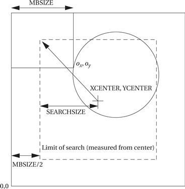
Figure 8.31 Block motion search parameters.
bestx = 0; besty = 0; /* initialize best location--none yet */
bestsad = MAXSAD; /* best sum-of--difference thus far */
for (ox = –SEARCHSIZE; ox < SEARCHSIZE; ox++) {
/* x search ordinate */
for (oy = –SEARCHSIZE; oy < SEARCHSIZE; oy++) {
/* y search ordinate */
int result = 0;
for (i = 0; i < MBSIZE; i++) {
for (j = 0; j < MBSIZE; j++) {
result = result + iabs(mb[i][j] −
search[i −ox + XCENTER][j − oy + YCENTER]);
}
}
if (result <= bestsad) { /* found better match */
bestsad = result;
bestx = ox; besty = oy;
}
}
The arithmetic on each pixel is simple, but we have to process a lot of pixels. If MBSIZE is 16 and SEARCHSIZE is 8, and remembering that the search distance in each dimension is 8 + 1 + 8, then we must perform
![]() (Eq. 8.4)
(Eq. 8.4)
difference operations to find the motion vector for a single macroblock, which requires looking at twice as many pixels, one from the search area and one from the macroblock. (We can now see the interest in algorithms that do not require a full search. To process video, we will have to perform this computation on every macroblock of every frame.) Adjacent blocks have overlapping search areas, so we will want to try to avoid reloading pixels we already have.
One relatively low-resolution standard video format, common intermediate format (CIF), has a frame size of 352 × 288, which gives an array of 22 × 18 macroblocks. If we want to encode video, we would have to perform motion estimation on every macroblock of most frames (some frames are sent without using motion compensation).
We will build the system using an FPGA connected to the PCI bus of a personal computer. We clearly need a high-bandwidth connection such as the PCI between the accelerator and the CPU. We can use the accelerator to experiment with video processing, among other things. Here are the requirements for the system:
| Name | Block motion estimator |
| Purpose | Perform block motion estimation within a PC system |
| Inputs | Macroblocks and search areas |
| Outputs | Motion vectors |
| Functions | Compute motion vectors using full search algorithms |
| Performance | As fast as we can get |
| Manufacturing cost | Hundreds of dollars |
| Power | Powered by PC power supply |
| Physical size and weight | Packaged as PCI card for PC |
8.6.3 Specification
The specification for the system is relatively straightforward because the algorithm is simple. Figure 8.32 defines some classes that describe basic data types in the system: the motion vector, the macroblock, and the search area. These definitions are straightforward. Because the behavior is simple, we need to define only two classes to describe it: the accelerator itself and the PC. These classes are shown in Figure 8.33. The PC makes its memory accessible to the accelerator. The accelerator provides a behavior compute-mv() that performs the block motion estimation algorithm. Figure 8.34 shows a sequence diagram that describes the operation of compute-mv(). After initiating the behavior, the accelerator reads the search area and macroblock from the PC; after computing the motion vector, it returns it to the PC.
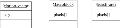
Figure 8.32 Classes describing basic data types in the video accelerator.
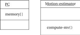
Figure 8.33 Basic classes for the video accelerator.
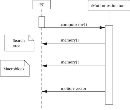
Figure 8.34 Sequence diagram for the video accelerator.
8.6.4 Architecture
The accelerator will be implemented in an FPGA on a card connected to a PC’s PCI slot. Such accelerators can be purchased or they can be designed from scratch. If you design such a card from scratch, you have to decide early on whether the card will be used only for this video accelerator or if it should be made general enough to support other applications as well.
The architecture for the accelerator requires some thought because of the large amount of data required by the algorithm. The macroblock has 16 × 16 = 256; the search area has (8 + 8 + 1 + 8 + 8)22 = 1,089 pixels. The FPGA probably will not have enough memory to hold 1,089 8-bit values. We have to use a memory external to the FPGA but on the accelerator board to hold the pixels.
There are many possible architectures for the motion estimator. One is shown in Figure 8.35. The machine has two memories, one for the macroblock and another for the search memories. It has 16 processing elements that perform the difference calculation on a pair of pixels; the comparator sums them up and selects the best value to find the motion vector. This architecture can be used to implement algorithms other than a full search by changing the address generation and control. Depending on the number of different motion estimation algorithms that you want to execute on the machine, the networks connecting the memories to the PEs may also be simplified.
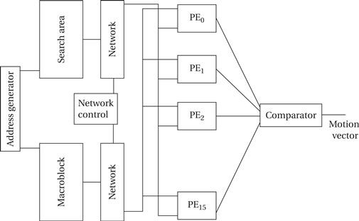
Figure 8.35 An architecture for the motion estimation accelerator [Dut96].
Figure 8.36 shows how we can schedule the transfer of pixels from the memories to the PEs in order to efficiently compute a full search on this architecture. The schedule fetches one pixel from the macroblock memory and (in steady state) two pixels from the search area memory per clock cycle. The pixels are distributed to the processing elements in a regular pattern as shown by the schedule. This schedule computes 16 correlations between the macroblock and search area simultaneously. The computations for each correlation are distributed among the processing elements; the comparator is responsible for collecting the results, finding the best match value, and remembering the corresponding motion vector.
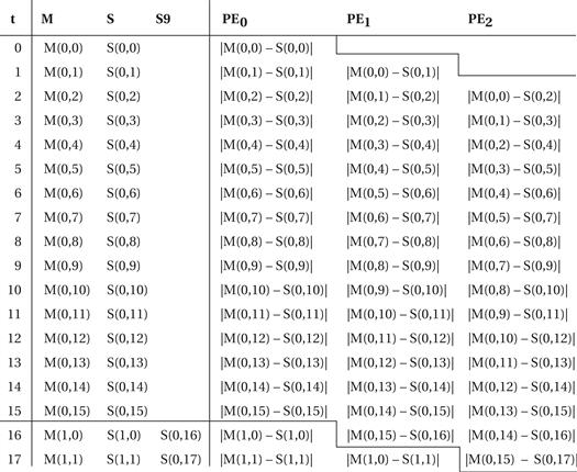
Figure 8.36 A schedule of pixel fetches for a full search [Yan89].
Based on our understanding of efficient architectures for accelerating motion estimation, we can derive a more detailed definition of the architecture in UML, which is shown in Figure 8.37. The system includes the two memories for pixels, one a single-port memory and the other dual ported. A bus interface module is responsible for communicating with the PCI bus and the rest of the system. The estimation engine reads pixels from the M and S memories, and it takes commands from the bus interface and returns the motion vector to the bus interface.
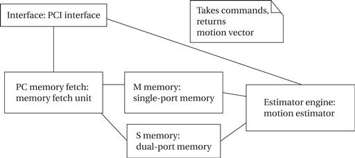
Figure 8.37 Object diagram for the video accelerator.
8.6.5 Component Design
If we want to use a standard FPGA accelerator board to implement the accelerator, we must first make sure that it provides the proper memory required for M and S. Once we have verified that the accelerator board has the required structure, we can concentrate on designing the FPGA logic. Designing an FPGA is, for the most part, a straightforward exercise in logic design. Because the logic for the accelerator is very regular, we can improve the FPGA’s clock rate by properly placing the logic in the FPGA to reduce wire lengths.
If we are designing our own accelerator board, we have to design both the video accelerator design proper and the interface to the PCI bus. We can create and exercise the video accelerator architecture in a hardware description language like VHDL or Verilog and simulate its operation. Designing the PCI interface requires somewhat different techniques because we may not have a simulation model for a PCI bus. We may want to verify the operation of the basic PCI interface before we finish implementing the video accelerator logic.
The host PC will probably deal with the accelerator as an I/O device. The accelerator board will have its own driver that is responsible for talking to the board. Because most of the data transfers are performed directly by the board using DMA, the driver can be relatively simple.
8.6.6 System Testing
Testing video algorithms requires a large amount of data. Luckily, the data represent images and video, which are plentiful. Because we are designing only a motion estimation accelerator and not a complete video compressor, it is probably easiest to use images, not video, for test data. You can use standard video tools to extract a few frames from a digitized video and store them in JPEG format. Open source for JPEG encoders and decoders is available. These programs can be modified to read JPEG images and put out pixels in the format required by your accelerator. With a little more cleverness, the resulting motion vector can be written back onto the image for a visual confirmation of the result. If you want to be adventurous and try motion estimation on video, open source MPEG encoders and decoders are also available.