
Three-phase systems
Publisher Summary
This chapter focuses on three-phase systems. Generation, transmission, and distribution of electricity via the National Grid system is accomplished by three-phase alternating currents. The voltage induced by a single coil when rotated in a uniform magnetic field, and is known as asingle-phase voltage. The majority of single-phase supplies are obtained by connection to a three-phase supply. A three-phase supply is generated when three coils are placed 120° apart and the whole rotated in a uniform magnetic field. A three-phase a.c. supply is carried by three conductors, called lines that are coloured red, yellow, and blue. A fourth conductor called the neutral—coloured black and connected through protective devices to earth—is often used with a three-phase supply. Three-phase motors are very robust, relatively cheap, and smaller have self-starting properties, provide a steadier output, and require little maintenance compared with single-phase motors.
1. Generation, transmission and distribution of electricity via the National Grid system is accomplished by three-phase alternating currents.
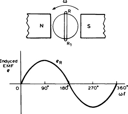
2. The voltage induced by a single coil when rotated in a uniform magnetic field is shown in Figure 18.1 and is known as a single-phase voltage. Most consumers are fed by means of a single-phase a.c. supply. Two wires are used, one called the live conductor (usually coloured red) and the other is called the neutral conductor (usually coloured black). The neutral is usually connected via protective gear to earth, the earth wire being coloured green. The standard voltage for a single-phase a.c. supply is 240 V. The majority of single-phase supplies are obtained by connection to a three-phase supply (see Figure 16.5).
3. A three-phase supply is generated when three coils are placed 120° apart and the whole rotated in a uniform magnetic field as shown in Figure 18.2(a). The result is three independent supplies of equal voltages which are each displaced by 120° from each other as shown in Figure 18.2(b).
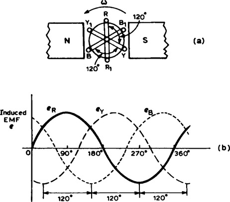
(i) The convention adopted to identify each of the phase voltage is: R—Red, Y—Yellow and B—blue, as shown in Figure 18.2.
(ii) The phase-sequence is given by the sequence in which the conductors pass the point initially taken by the red conductor. The national standard phase sequence is R, Y, B.
5. A three-phase a.c. supply is carried by three conductors, called ‘lines’ which are coloured red, yellow and blue. The currents in these conductors are known as line currents (IL) and the p.d.’s between them are known as line voltages (VL). A fourth conductor, called the neutral (coloured black, and connected through protective devices to earth) is often used with a three-phase supply.
6. If the three-phase windings shown in Figure 18.2 are kept independent then six wires are needed to connect a supply source (such as a generator) to a load (such as a motor). To reduce the number of wires it is usual to interconnect the three phases. There are two ways in which this can be done, these being: (a) a star connection, and (b) a delta, or mesh, connection. Sources of three-phase supplies, i.e. alternators, are usually connected in star, whereas three-phase transformer windings, motors and other loads may be connected either in star or delta.
(i) A star-connected load is shown in Figure 18.3 where the three line conductors are each connected to a load and the outlets from the loads are joined together at N to form what is termed the neutral point or the star point.
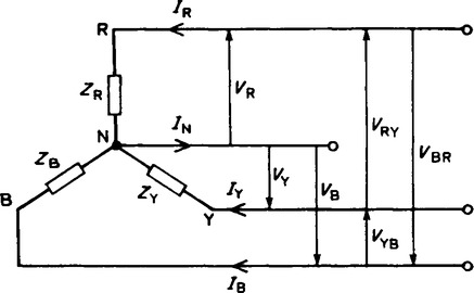
(ii) The voltages, VR, VY and VB are called phase voltages or line to neutral voltages. Phase voltages are generally denoted by VP.
(iii) The voltages, VRY, VYB and VBR are called line voltages.
(iv) From Figure 18.3 it can be seen that the phase currents (generally denoted by Ip) are equal to their respective line currents IR, IY and IB, i.e. for a star connection:
(v) For a balanced system: IR = IY = IB, VR = VY = YB, VRY = VYB = VBR, ZR = ZY = ZB and the current in the neutral conductor, IN = 0. When a star connected system is balanced, then the neutral conductor is unnecessary and is often omitted.
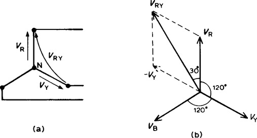
(vi) The line voltage, VRY, shown in Figure 18.4(a) is given by VRY = VR-VY. (VY is negative since it is in the opposite direction to VRY.) In the phasor diagram of Figure 18.4(b), phasor VY is reversed (shown by the broken line) and then added phasorially to VR, (i.e. VRY = VR + (-VY)). By trigonometry, or by measurement, VRY = √3VR, i.e. for a balanced star connection:
A phasor diagram for a balanced, three-wire, star-connected, 3-phase load having a phase voltage of 240 V, a line current of 5 A and a lagging power factor of 0.966 is shown in Figure 18.5 The phasor diagram is constructed as follows:
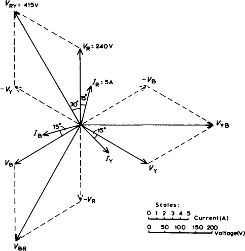
(i) Draw VR = VY = VB = 240 v and spaced 120° apart.
(ii) Power factor = cos ϕ = 0.966 lagging. Hence the load phase angle is given by arccos 0.966, i.e. 15° lagging. Hence
lagging VR, VY and VB respectively by 15°.
(iii) VRY = VR−VY (phasorically). By measurement, VRY = 415 V (i.e. √3(240)) and leads VR by 30°. Similarly, VYB = VY−VB and VBR = VB−VR.
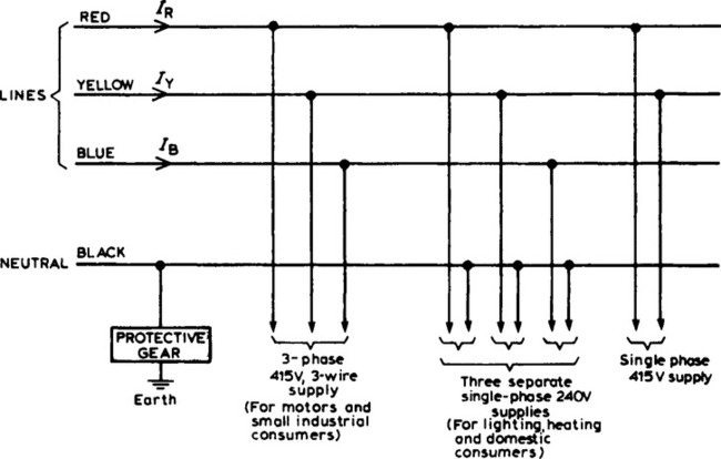
(vii) The star connection of the three phases of a supply, together with a neutral conductor, allows the use of two voltages — the phase voltage and the line voltage. A 4-wire system is also used when the load is not balanced. The standard electricity supply to consumers in Great Britain is 415/240 V, 50 Hz, 3-phase, 4-wire alternating voltage, and a diagram of connections is shown in Figure 18.6
(i) A delta (or mesh) connected load is shown in Figure 18.7 where the end of one load is connected to the start of the next load.
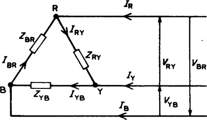
(ii) From Figure 18.7, it can be seen that the line voltages VRY, VYB and VBR are the respective phase voltages, i.e. for a delta connection:
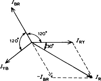
(iii) Using Kirchhoff’s current law in Figure 18.7,
From the phasor diagram shown in Figure 18.8, by trigonometry or by measurement, IR = √3 IRY, i.e for a delta connection:
9. The power dissipated in a three-phase load is given by the sum of the power dissipated in each phase. If a load is balanced then the total power P is given by:
P = 3 × power consumed by one phase.
The power consumed in one phase = ![]() (where ϕ is the phase angle between VP and IP).
(where ϕ is the phase angle between VP and IP).
Hence for either a star or a delta balanced connection the total power P is given by:
10. Power in three-phase loads may be measured by the following methods:
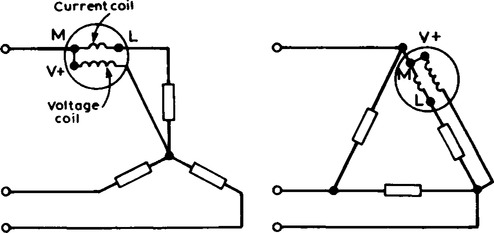
(i) One-wattmeter method for a balanced load
Wattmeter connections for both star and delta are shown in Figure 18.9 Total power = 3 X wattmeter reading.
(ii) Two-wattmeter method for balanced or unbalanced loads A connection diagram for this method is shown in Figure 18.10 for a star-connected load. Similar connections are made for a delta-connected load.
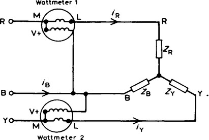
Total power = sum of wattmeter readings = P1 + P2.
The power factor may be determined from:
It is possible, depending on the load power factor, for one wattmeter to have to be ‘reversed’ to obtain a reading. In this case it is taken as a negative reading.
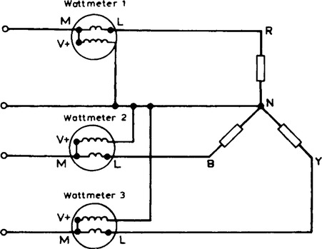
(iii) Three-wattmeter method for a three-phase, 4-wire system for balanced and unbalanced loads (see Figure 18.11)
(i) Loads connected in delta dissipate three times more power than when connected in star to the same supply.
(ii) For the same power, the phase currents must be the same for both delta and star connections (since power = 3I2pRp), hence the line current in the delta-connected system is greater than the line current in the corresponding star-connected system. To achieve the same phase current in a star-connected system as in a delta-connected system, the line voltage in the star system is √ times the line voltage in the delta system.
Thus for a given power transfer, a delta system is associated with larger line currents (and thus larger conductor cross-sectional area) and a star system is associated with a larger line voltage (and thus greater insulation).
12. Advantages of three-phase systems over single-phase supplies include:
(i) For a given amount of power transmitted through a system, the three-phase system requires conductors with a smaller cross-sectional area. This means a saving of copper (or aluminium) and thus the original installation costs are less.
(ii) Two voltages are available (see para. 7).
(iii) Three-phase motors are very robust, relatively cheap, generally smaller, have self-starting properties, provide a steadier output and require little maintenance compared with single-phase motors.