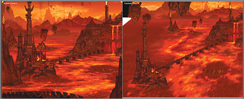
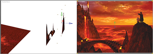
Turn on the visibility for the RockCityLf precomp, and move it toward the camera on the Z-axis. Watch for where the precomp intersects the ground plane. The projection of the ground plane has a bright spot where the lava waterfall meets the ground, so that layer must be positioned on top of that spot (Figure 15-39). As you move the precomp toward the camera, it becomes too large in the frame. If you carefully move the precomp only on the Z-axis, it will stay in the correct relative position to the other elements, and you can uniformly scale it down to the correct size. Refer back to the ViewOfHadesForAE comp for proper positioning.
Figure 15-39: RockCityLf positioned correctly on the ground plane
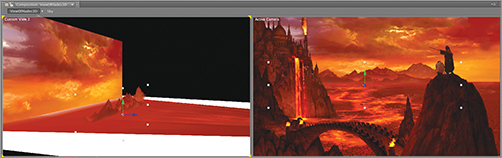
Make sure RockCityLf intersects the ground plane and isn’t raised above it. It’s possible to position a layer so that it looks correct in the active camera but doesn’t correctly intersect the ground plane (Figure 15-40).
Figure 15-40: RockCityLf incorrectly positioned so that it doesn’t intersect the ground plane
Notice that the base of the layer is cut off in a straight, flat line by the ground plane and, therefore, lacks the integration of the original painting. This is one of the limitations of working with flat planes and why the projected ground plane requires painting at the base of each layer to blend better.
Positioning the F-grBridge Precomp
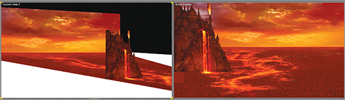
Turn on the visibility of the F-grBridge precomp. This layer is trickier to position because you don’t see where it intersects the ground plane. It needs to be slightly above the ground plane in its final position. Move it forward on the Z-axis until it’s halfway between RockCityLf and Camera 1. Scale it down more so you can see it in the Active Camera view. The final scale should be around 6.2%. Work back and forth between the Custom view and the Active Camera view to adjust its positioning and scaling. In the Active Camera view, all layers should end up in the exact same location as they appear in the original painting (Figure 15-41).
Figure 15-41: Position of the F-grBridge precomp
Positioning the F-grSpire Precomp
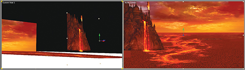
Turn on the visibility of the F-grSpire precomp. It should be the closest layer to the camera, so move it forward on the Z-axis until it’s slightly in front of the F-grBridge layer. As with the previous layer, you can’t see where the layer intersects the ground plane, so you need to visualize where it would be in 3D space. When it’s in the correct position in Z space, scale it down and move it in the X-axis and Y-axis to position it as it was in the original painting (Figure 15-42).
Figure 15-42: Position of the F-grSpire precomp
Positioning the MountainsFr Layer
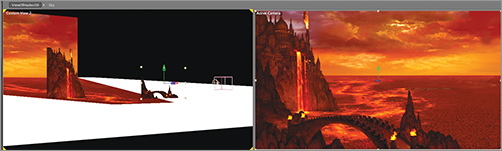
Turn on the visibility of the MountainsFr layer. This isn’t a precomp, but a regular layer composed of a single image with no animated elements. Move MountainsFr back on the Z-axis until it’s close to the sky. There are two more layers of mountains behind this layer, so make sure you leave room for them. Scale up the MountainsFr layer, and position it on the X-axis and Y-axis until it matches the position in the original painting (Figure 15-43). Double-check that the MountainsFr layer intersects the ground plane.
Figure 15-43: Position of the MountainsFr layer
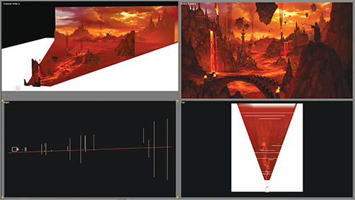
Position the remaining layers on your own, except for TallBridge, BridgeJoin, and Bridge. Remember, the layers are positioned in true 3D space for this project, and each layer must intersect the ground plane as it does in the original painting. When you’re finished, the project should look like Figure 15-44 in these four different views. You can check your work by comparing it to ViewOfHadesAllPlanes.aep in the DVD materials.
Figure 15-44: Four views of the final layers positioned in 3D space
Angling the TallBridge Precomp
So far, all the layers except the ground plane have been positioned facing straight on to the camera. Now you’ll set up angled layers to give the composition additional dimensionality. The RockCityRt precomp and the RockCityLedge layer are connected by a tall bridge. Rotate the TallBridge comp so it connects the two layers in 3D space (Figure 15-45). Because you aren’t giving the bridge an extreme rotation, it isn’t distorted.
Figure 15-45: Rotating a plane to give added dimensionality
Projecting and Painting the Longer Bridge
The second bridge, named Bridge, connects the RockCityRt and RocksLf precomps. Unlike the former example, if you attempt to rotate the bridge layer to connect the two elements, the bridge becomes terribly distorted because of the severe angle of rotation (Figure 15-46).
Figure 15-46: Bridge layer rotated too much to yield acceptable results
Creating a White Solid for Projection
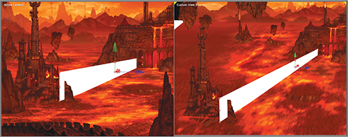
To create this bridge, you’ll use a variation on the technique you used to project an image onto the ground plane. Create a new white solid, 1000 × 200 pixels, and make it 3D. Rename it WhiteSolidBridge, and place it in position where the bridge should be between the RockCityRt and RocksLf precomps (Figure 15-47).
Figure 15-47: WhiteSolidBridge positioned where the final bridge should be
Adding the Reference and Projection Layers
Select the original Bridge layer, and duplicate it. Rename one copy BridgeReference and the other BridgeProjection. Make BridgeReference 2D, and move it to the top of the layer stack. Confirm that BridgeProjection is 3D. If it isn’t, make it so. Copy the position of Camera 1, and paste it onto BridgeProjection. Now, move BridgeProjection slightly in front of the camera, and use the 2D BridgeReference layer to match the position in the original painting. This process is identical to how you projected the ground plane.
You’ll now project the image from BridgeProjection onto WhiteSolidBridge, which is positioned where the bridge should be. Because you can have only one projection at a time, you must turn off the visibility of the GroundPlaneProjection layer. The ground plane turns white. Turn the ground plane visibility off as well in order to concentrate on the bridge.
Changing the Material Options
Set BridgeProjection’s Material Options to:
- Casts Shadows: Only
- Light Transmission: 100%.
Set the WhiteSolidBridge layer’s Material Options to:
- Accepts Shadows: On
- Accepts Lights: Off
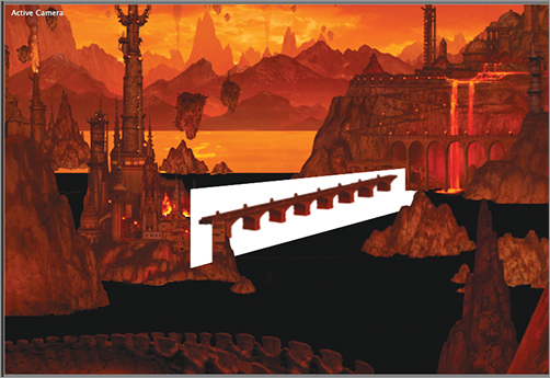
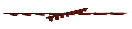
The spotlight should now be projecting an image of the bridge onto WhiteSolidBridge (Figure 15-48). Because you can have only one image projected in an After Effects comp, and a projection is already in use for the ground plane, you need to create a distorted version of this bridge that can be used on a rotated plane. You’ll do this in Photoshop.
Figure 15-48: Image of the bridge projected onto WhiteSolidBridge
Take a Screen Shot of the Projected Bridge
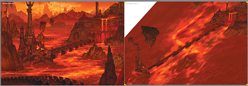
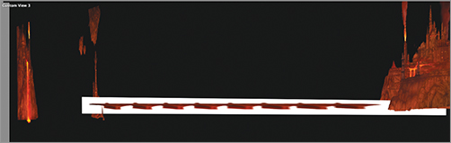
Rotate one of the custom views around so that WhiteSolidBridge is flat on to the view, and as large as possible. The bridge image looks extremely distorted (Figure 15-49). Take a screen shot of that angle:
- In Windows, press Alt+Print Screen. Open a new file in Photoshop, and paste the screen shot in from the clipboard.
- On the Mac, a flexible screen-shot application called Grab is located in the Utilities subfolder in the Applications folder. Open Grab, press Command+Shift+A, and then click+drag over the area you want to capture. Copy the resulting file, and import it into Photoshop.
Figure 15-49: Straight-on view of the projected bridge in the custom views
Distort the Original Bridge to Match the Projected Bridge
In Photoshop, copy the original Bridge layer from the ViewOfHadesforAE.psd file, and paste it into the new file on top of the screen shot (Figure 15-50). Name the new layer BridgeDistort.
Figure 15-50: Screen shot of the distorted bridge imported into Photoshop, and original bridge pasted on top
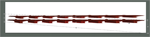
Transform/Distort the original bridge so it matches the distorted bridge from After Effects. It can be tricky to get the bridge to match the distorted bridge, so take your time and get it as close as possible (Figure 15-51).
Figure 15-51: Original bridge distorted to match the projected distorted bridge
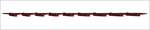
Enlarge the canvas on the left, and add another section to the bridge. This allows for where the bridge extends behind the foreground layer, which comes into view when you move the camera (Figure 15-52). You can retouch any area that looks soft. Delete the reference layer, and keep just the distorted bridge on its own layer. Name the file BridgeDistort.psd. You can check your work on distorting the bridge against the demo file in Chapter 15 ViewOfHadesAfterEffects (Footage) BridgeDistort.psd on the DVD.
Figure 15-52: Final distorted bridge with an additional section added to the left
Import the BridgeDistort Layer Into After Effects
Import this file into After Effects, drag it into the ViewOfHades3D comp, and set it to 3D. Move, scale, and rotate the BridgeDistort layer to match the position of WhiteSolidBridge. Now, with the distorted bridge in place (Figure 15-53), do the following:
- Delete WhiteSolidBridge, onto which the bridge was projected.
- Turn off the BridgeProjection and BridgeReference layers.
- Turn the ground plane solid back on.
- Turn GroundPlaneProjection back on.
You can check your work against the file ViewOfHadesProjectedBridge.aep on the DVD.
Figure 15-53: Distorted bridge in place