
]>
Problems
Chapter 1
P1.1For a simple lossless medium, derive the wave equations for E and H.
P1.2Obtain the wave Equations 1.18 and 1.19 subject to the Lorentz condition given by Equation 1.21.
P1.3Obtain Equation 1.27.
P1.4Show that for a time-harmonic case, Equation 1.22 reduces to Equation 1.50.
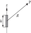
P1.5a.Obtain the expression for the time-harmonic retarded potential A for a current element of small length h located on the z-axis as shown in the figure.
b.Hence obtain the electric and magnetic fields at P. Assume that the current in the filament is I0(A).
c.In the far zone, that is, for R ≫ λ, h ≪ λ, obtain E , H , E × H, and ⟨S⟩.
P1.6Lecture module-week 1 is devoted to reviewing Maxwell’s equations. In the undergraduate prerequisite course(s), considerable amount of time is spent in arriving at these equations based on experimental laws. In the process, vector calculus and coordinate systems are explained at length. The questions for the week make you revise the undergraduate background. You can look into the textbook you used in your undergraduate prerequisite course or search the internet in answering these two questions. The questions are:
Equation 1.1, Equation 1.2, Equation 1.3 and Equation 1.4 are in differential form. Write down the corresponding equations in the integral form.
The integral form of Equation 1.1, Faraday’s law, allows you to compute the voltage induced (emf) in a circuit. There are two components to it: (i) transformer emf and (ii) motional emf. Give an example where only (i) is induced; give an example where only (ii) is induced and give a third example where both (i) and (ii) are induced. In the third case, if your interest is in computing the total induced voltage and not in separating them into the two components, is there a simpler way of computing the total induced voltage? Illustrate the simpler way through an example.
P1.7This question is to make you think about the concept of retarded potentials. Equations 1.22 and 1.24 are useful in answering this question. Note that Equation 1.22 is written when the source is a volume current element. For a filamentary current source, you will replace J dV by I dL.
Suppose the source is a differential filamentary current element located at the origin along the y-axis, where
Obtain the differential vector potential d→AP
Note the following. You can use a bold letter or a letter with an arrow on the top to denote a vector. The hat on the top of y denotes a unit vector in the y-direction in the Cartesian system of coordinates (rectangular coordinate system).
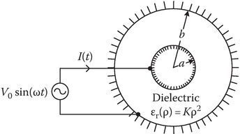
P1.8Consider a cylindrical capacitor of length ℓ. The radius of the inner cylinder is a and the radius of the outer cylinder is b. The dielectric constant of the dielectric inside the capacitor varies as (K is a constant)
Show that the conduction current I(t) in the wire is the same as the displacement current in the capacitor.
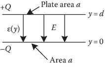
P1.9A parallel plate capacitor is of cross-sectional area A and is filled with a dielectric material whose permittivity varies linearly from ε = ε1 at one plate (y = 0) to ε = ε2 at the other plate (y = d). Neglecting fringing effects, determine the capacitance.
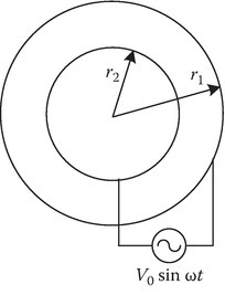
P1.10Show that the displacement current between two concentric cylindrical conducting shells of radii r1 and r2, r2 > r1 is exactly the same as the conduction current in the external circuit. The applied voltage is V = V0 sin ωt.
P1.11Derive (2.42), (2.43) and (2.44), based on Section 1.6.
P1.12Determine the vector H field at a general point in free space due to a DC current I A in an infinitely long filament lying on the z-axis. Use Ampere’s law and symmetry arguments.
P1.13Suppose that an infinite sheet of current of surface current density ˆxKA/m
P1.14Equation 1A.14 is the well-known divergence theorem. Less well known are some more theorems that can be derived from the divergence theorem. These are (1A.68) and (1A.69). Prove them
P1.15Equation 1A.66 is the well-known Stoke’s theorem. Less well known are some more theorems that can be derived from the Stoke’s theorem. One of them is (1A.70). Prove it.
P1.16Derive wave equation for electroquasistatics and magnetoquasistatics discussed in Section 1.5. Assuming the medium is free space and the fields vary with only z coordinate, obtain their form.
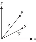
P1.17Derive an expression for ψ, the angle between the position vectors r and r′. Express it in terms the of their spherical coordinates.
Chapter 2
P2.1Derive Equation 2.1, Equation 2.2 and Equation 2.3.
P2.2Assume that the time-harmonic fields in a perfect conductor are zero. Show that boundary conditions at the interface of a perfect conductor are given by Equations 2.23 or 2.24 or 2.25 or 2.26.
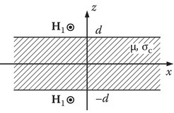
P2.3The principle of induction heating is explored in this problem. A sheet of metal (good conductor) of conductivity σc is inserted into AC magnetic field whose value at the surface z = ±d is assumed to be H1=−ˆyH1
Show that the AC magnetic field in the conductor is given by H(z) = H1(cosh τz/cosh τd) where τ = (1 + j)/δ and δ=1√πfμσc
δ=1πfμσc−−−−−√ . Assume that δ ~ d.Show that J=Jˆx
J=Jxˆ , where J = τH1(sinh τz/cosh τd).Find the power consumed by the sheet of length (along x-axis) 1 m and width (along y-axis) 1 m. You do not have to show it for the homework, but a little further work will show that the power consumed per unit volume is maximized if d ≈ 1.125 δ.
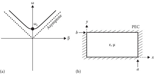
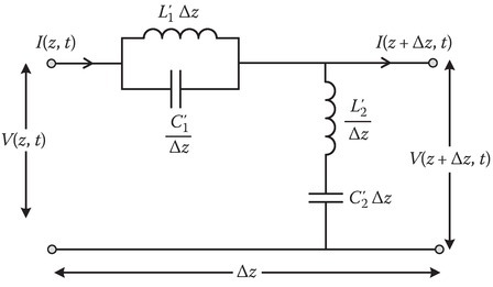
P2.4Figure P2.4a shows the circuit equivalent of a section Δz of a transmission line.
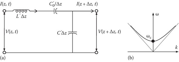
FIGURE P2.4
Find the differential equation for the instantaneous current I(z, t),
Assume that the current varies harmonically in space and time, that is,
I(z,t)=Iexp[j(ωt−kz)].I(z,t)=Iexp[j(ωt−kz)]. Find the relation between ω and k.
A sketch of ω and k is given in Figure P2.4b. Find the value of the cutoff frequency ωc and the slope of the asymptotes (dotted lines).
P2.5The electric and magnetic fields of a coaxial transmission line whose cross-section is shown in Figure P2.5 are given as follows: The line connects a source to a load.
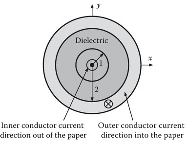
FIGURE P2.5
Determine C and D.
Let the length of the line be 30 m. Find the source power, power lost in the line, and the power received by the load.
There could be a misprint in the statement: “Atρ=2:E=Cˆaρ+0.02ˆazV/m
Atρ=2:E=Caˆρ+0.02aˆzV/m .” Find the misprint and correct it. Give one or two reasons as to why you think there is a misprint. This misprint perhaps has not affected your answers to parts (a) and (b).
P2.6A loss-free nonuniform transmission line has
where L′ and C′ are per meter values of the series inductance and parallel capacitance of the transmission line, respectively.
Determine the partial differential equation for the instantaneous voltage V(z, t).
For an exponential transmission line
L′(z)=L0exp(qz),C′(z)=C0exp(−qz),L′(z)=L0exp(qz),C′(z)=C0exp(−qz), assuming V(z, t) = V0 exp[j(ωt − kz)], determine the relation between ω and k.
P2.7A distortionless line satisfies the condition
Find α, β, and Z0 for such a line.
P2.8The magnetic field vector-phasor of a plane wave is given by
Use the properties of a plane wave to determine ˉE(x,t)
E¯¯¯(x,t) .You probably recognized from the expression for ˉE(x,t)
E¯¯¯(x,t) that it is circularly polarized. Is it L wave or R wave?Had you used Equation P2.1 to determine the polarization, you would get the same answer as that for (b). Check this out by drawing the diagram like Figure 2.6b or c.
Determine the instantaneous power density ˉS(x,t)
S¯¯(x,t) and active power density 〈ˉSR(x)〉⟨S¯¯R(x)⟩ .
P2.9A conducting film of impedance 377 Ω/square is placed a quarter-wavelength in air from a plane conductor (PEC) to eliminate wave reflection at 9 GHz. Assume negligible displacement currents in the film. Plot a curve showing the fraction of incident power reflected versus frequency for frequencies 6–18 GHz.

P2.10Calculate the reflection coefficient and percent of incident energy reflected when a uniform plane wave is normally incident on a Plexiglas radome (dielectric window) of thickness 3/8″, relative permittivity εr = 2.8, with free space on both sides. λ0 = 20 cm. Repeat for λ0 = 10 cm. Repeat for λ0 = 3 cm. Comment on the results obtained.
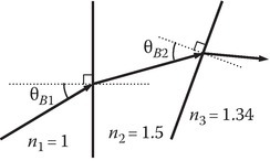
P2.11A green ion laser beam, operating at λ0 = 5.45 μm, is generated in vacuum, and then passes through a glass window of refractive index 1.5 into water with n = 1.34. Design a window to give zero reflection at the two surfaces for a wave polarized with E in the plane of incidence, that is, find θB2 − θB1.
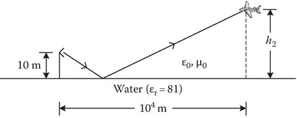
P2.12The transmitting antenna of a ground-to-air communication system is placed at a height of 10 m above the water, as shown in the figure. For a separation of 10 km between the transmitter and the receiver, which is placed on an airborne platform, find the height h2 above water of the receiving system so that the wave reflected by the water does not possess a parallel-polarized component. Assume that the water surface is flat and lossless [Reference 2 of Chapter 2].
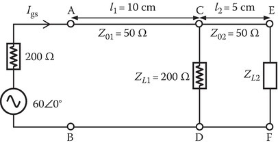
P2.13A source Vgs = 60∠0° with internal impedance 200 Ω is connected to a resistive load ZL1 = 200 Ω by a two-wire lossless transmission line in air (velocity of propagation c = 3 × 10⁸ m/s) of length l1 = 10 cm and characteristic impedance Z01 = 50 Ω. This load is connected to another load ZL2 by the two-wire transmission line of length l2 = 5 cm. Let the load ZL2 be replaced by a short-circuit. Determine the current Igs for two values of frequency (f):
f = 60 Hz. This is the frequency of the house current.
Hint: For very small values of βl, tan βl may be approximated by zero.
f = 1.5 GHz.
P2.14A dielectric slab of dielectric constant εr is shown in the figure. A wave is incident on it from one of its ends at an oblique angle 0° < θi < 90°. Show that for εr ≥ 2, the wave is contained in the slab for all angles of θi.

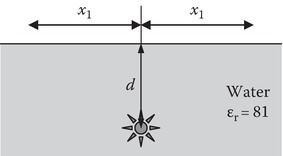
P2.15A source that radiates isotropically is submerged at a depth d below the surface of water as shown in the figure. How far in the x-direction (both positive and negative) can an observer (on the water surface) go and still receive the radiation? Assume that the water is flat lossless with a dielectric constant of 81 [Reference 2 of Chapter 2].
P2.16Obtain Equation 2.112, Equation 2.113, Equation 2.114 and Equation 2.115.
P2.17The reflection coefficient Γ is real for a dielectric–dielectric interface for 0° < θ1 < θc, where θc is the critical angle. For θ2 > θc, there is total reflection and the magnitude of the reflection coefficient is 1. Thus, in the range θc < θ2 < 90°, the reflection coefficient may be represented as Γ = ejϕ. Plot ϕ versus θ1 for (a) s wave and (b) p wave. Take n1 = 1.5 and n2 = 1.0. In the above θ1 is the angle of incidence.
P2.18a.Obtain Equation 2.126.
b.Calculate the radiated power leaving the surface of a cylinder of radius ρ and length 1 m. Assume that the cylinder is in the far zone and the source is a constant harmonic current ˜I
P2.19The electric field phasor of an elliptically polarized wave is given below:
Show that this field can be expressed as the sum of the fields of a left circularly polarized wave (LCP) and a right circularly polarized wave (RCP). Write the complete expression for the electric field phasor of the (a) LCP wave and (b) RCP wave.
P2.20See below figure. Determine the electric field of the reflected wave (ER) when the electric field of the incident wave (assume normal incidence) is

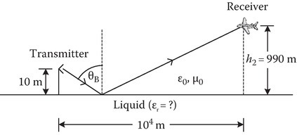
P2.21The transmitting antenna of a ground-to-air communication system is placed at a height of 10 m above a liquid, as shown in the figure. Given that the separation of 10 km between the transmitter and the receiver, which is placed on an airborne platform, and the height h2 = 990 m above the liquid of the receiving system so that the wave reflected by the liquid does not possess a parallel-polarized component, determine the relative permittivity of the liquid. Assume that the liquid surface is flat and lossless.
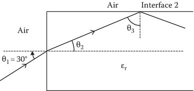
P2.22A longitudinal section of a dielectric is shown in the figure. If θ1 = 30° and θ3 is the critical angle at interface 2, determine £r of the dielectric.
P2.23Refer to the figure. The instantaneous electric field of the incident wave consisting of a p as well as a s wave is given by
Determine the angle of incidence.
Let ε2 = Aε0, μ2 = μ0, and the angle of incidence is the Brewster angle. Determine A. Also determine (i) Γs and (ii) the instantaneous electric field of the reflected wave.

P2.24a.A p wave is propagating in the ζ-direction as shown in Figure P2.24a. Its electric field is given by
Determine the angle θ. Determine ˆHp
b.The instantaneous electric field of an incident wave (see Figure P2.24b) consisting of both p and s waves is given by
Determine θ1.
Determine θr.
If kx = 0.5 rad/m, determine the frequency f in Hertz and wavelength λ in meters.
Determine the polarization of the incident wave.
Find the value of ε2 for which the incident angle is equal to the critical angle.
The value of ε2 for which the reflected wave is linearly polarized.
If ε2 = 16ε0, determine the instantaneous electric field of the reflected wave and the instantaneous electric field of the transmitted wave.
If ε2 = 25ε0, determine the instantaneous electric field of the reflected wave.
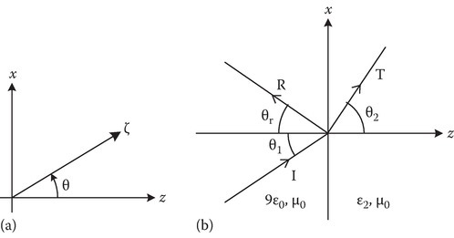
FIGURE P2.24
P2.25The phasor electric field of a circularly polarized standing wave in free space is given by
Determine
The magnetic field ˜H
H˜ Instantaneous power density
Time-averaged power density
Assuming the standing wave is linearly polarized and its phasor electric field is given by
(P2.3)˜E=ˆxE0sin(kz).E˜=xˆE0sin(kz).
Determine the quantities in (a), (b), and (c).
Let the field given by Equation P2.2 exist between two perfectly conducting plates located at z = 0 and z = d. Find the relation between the angular frequency ω and d.
P2.26The z = 0 plane is a sheet of current carrying a harmonic surface current density
Determine the vector phasor electric field ˜E
P2.27A s-wave in medium 1 is incident (plane of incidence x–z plane) on medium 2 at an angle θ with the normal to the interface, that is, the phasor electric field of the incident wave is given by
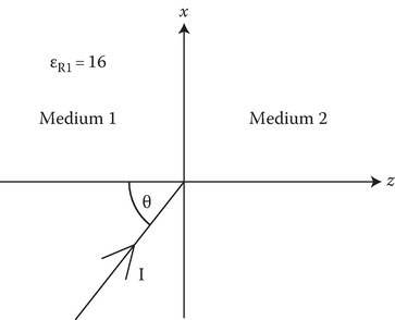
Medium 1 is a dielectric with relative permittivity εR1 = 16 and the frequency is 10 GHz.
Determine k1.
Let medium 2 be a perfect conductor. (i) Write down the expression for the vector magnetic field HR of the reflected wave. (ii) Reflection coefficient ΓS. (iii) Power reflection coefficient. (iv) Total magnetic field H(x, y, 0−, t). (v) Surface current K at the interface z = 0.
Let medium 2 be a dielectric with relative permittivity εR2 = 9. (i) Determine the critical angle θc. (ii) Take θ = θc + 5°. The time domain expression for the x-component of the reflected magnetic field may be written as HRx=Acos(ωt+bx+cz+2ϕ)
HRx=Acos(ωt+bx+cz+2ϕ) : determine ω, A, b, c, ϕ.The medium 2 is the same as part (c). A p-wave of double the electric field strength of s-wave is added to the incident wave.
Write down the expression for the electric field EI of the incident wave consisting of both s- and p-waves in terms of E0 and θ.
Determine the Brewster angle θB.
If θ = θB, write down the expressions for the time domain reflected electric field ER and the time domain transmitted electric field ET.
P2.28Figure P2.28 shows the circuit equivalent of a section Δz of a transmission line. Find the differential equation for the instantaneous voltage V(z, t). Your solution should not include the current variable I(z, t).

FIGURE P2.28
P2.29The region z > 0 is a perfect conductor and the region z < 0 is free space. Let the magnetic field in free space be given by H=ˆycos(3×10⁸t−4x)(A/m)
Determine the surface current density ⊥Js
⊥Js at P(4,2,0) at t = 5 ns.Determine the surface charge density ρs at P(4,2,0) at t = 5 ns.
P2.30The electric field intensity at the origin is 2ˆx−10ˆy+3ˆz(V/m)
If the origin lies on a perfectly conducting surface while the material adjacent to the origin has εR = 10, μR = 2, and σ = 0, find the magnitude of the surface charge density at the origin at t = 0.
P2.31Wave propagation in an unbounded good conductor may be studied through a transmission line model. The below figure shows the circuit equivalent of a section Δz of a transmission line.
Obtain the first-order coupled differential equations for V(z, t) and I(z, t). Eliminate V and obtain a second-order differential equation for I.
Assume that the voltage varies harmonically in space and time, that is,
I(z,t)=I0exp[j(ωt−kz)],I(z,t)=I0exp[j(ωt−kz)], find the relation between ω and k diagram.
Sketch the ω–k diagram.
Using your knowledge of wave propagation in a good conductor, express L′ and G′ of the figure in terms of μ and σ of the conductor.

P2.32The following figure shows two nonconducting media with a boundary at z = 0. The parameters of the medium and the electric field expressions in the two media are also written in the figure.
Find A, B, C constants in these expressions.
Determine the expression for the vector H2.

P2.33The oblique wave propagation from an optically dense medium (medium 1) to an optically rare medium (medium 2) exhibits the phenomenon of critical angle. Let n1 = 1.5 and n2 = 1.
Find the critical angle. If the incident wave is an s wave, determine the depth of penetration of the evanescent wave for an angle of incidence 5° more than the critical angle. Find the phase velocity of the evanescent wave along the interface. Express your answer in terms of the wave number in the second medium.
Now consider the propagation of a p wave. Find the Brewster angle.
P2.34In Section 2.4, the AC resistance RAC was obtained using (2.36). Another way of obtaining RAC is by calculating the impedance ZAC. Such an impedance is defined as the voltage difference at the top of the conductor divided by the current entering the conductor. Show you get the same answer for RAC as that of (2.38). Hint: See (8.135).
P2.35Do Problem P2.13 when ZL2 is an open-circuit.
P2.36Use (1.50) to obtain (2.121) by considering the dAz due to differential length along the z-axis and integrating for the infinite length line.
Chapter 3
P3.1Obtain Equations 3.29, 3.32, and 3.33.
P3.2A standard X-band rectangular waveguide with inner dimensions of a = 2.286 cm (0.9″) and b = 1.106 cm (0.4″) is filled with lossless polystyrene (εr = 2.56). For the lowest order mode of the waveguide, determine at f = 10 GHz the following values:
Cutoff frequency fC (GHz).
Guide wavelength λg (in cm).
Wave impedance.
Phase velocity.
P3.3Show that 1/λ2g=1/λ2−1/λ2c
P3.4The z = 0 plane is a sheet of current carrying a harmonic surface current density
Assume the medium is free space.
Write the differential equation for the phasor vector magnetic potential A.
What component of the vector potential will be nonzero? On what coordinate does this component depend? Write the ordinary differential equation satisfied by this component. Find its solution valid for z > 0. The solution will contain an undetermined constant A0.
Determine the vector phasor electric field E and magnetic field H in terms of A0.
Use Amperes law to relate A0 with K0.
Calculate the radiated power per square meter.
What will be the values of E and H if ω = 0.
Write down the electric and magnetic fields E and H for z < 0.
P3.5Design a circular waveguide filled with a lossless dielectric medium whose relative permeability is unity. The waveguide must operate in a single dominant mode over a bandwidth of 1.5 GHz. Assume that the radius of the waveguide is 1.12 cm.
Find the dielectric constant of the medium that must fill the waveguide to meet the desired specifications.
Find the lower and upper frequencies of operation.
P3.6Design a rectangular waveguide (determine a and b) for use in a microwave oven to operate at a frequency f = 900 MHz. Let a/b = 1.8. Choose a so that the frequency of the magnetron is 30% above the cutoff frequency of the TE10 mode, that is,
Determine the guide wavelength.
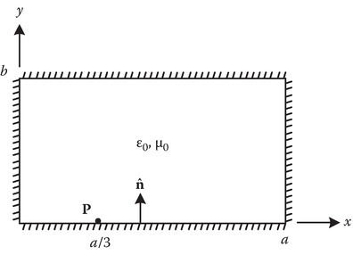
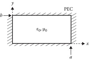
P3.7Refer to the figure, given that the electric field Ey = 0.5 sin(πx/a) e−jβz in a rectangular waveguide (TE10 mode), determines the surface charge density ρs on the bottom PEC plate at the point P (a/3, 0, 0).
P3.8Let a rectangular waveguide have a discontinuity in dielectric at z = 0, that is, ε1 and μ1 for z < 0, and ε2 and μ2 for z > 0.
Determine f/fc10 for which there is no reflection. In the above, f is the signal frequency and fc10 is the cutoff frequency of the TE10 mode.
Repeat for TMmn mode, that is, find f/fcmn for which there is no reflection (for TMmn mode).
P3.9a.Obtain the harmonic solution to the partial differential equation of Problem P2.28 by assuming V(z, t) = V0 ej(ωt−βz), that is, obtain the relation between ω and β.
b.A sketch of ω–β diagram is shown in figure (a). Obtain the value of ωc and the slope of the dotted asymptotic line.
c.Show that the transmission line in Problem P3.9 can be made to represent a TEmn mode of propagation in a waveguide by a proper choice of L′,L′1
d.Apply above results to TE23 mode in a rectangular waveguide shown in figure (b) and express L′1
e.Can the same transmission line represent TM23 mode. Give reasons for your answer.
P3.10The z-component of the magnetic field of TEz11
Determine
a
b
Cutoff frequency fc.
Assuming the signal frequency f = 1010 Hz, determine β.
c=1√μ0ε0=3×10⁸m/s.c=1μ0ε0−−−−√=3×108m/s.
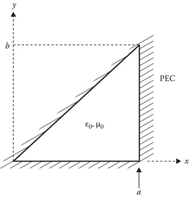
P3.11Figure shows a conducting waveguide with cross section of a right-angled isosceles triangle.
Part A:
For TM modes show that the z-component of the electric field:
Ez=Cmn[(sinmπxa)(sinnπya)−(sinnπxa)(sinmπya)].What are the allowed values of m and n?
Find the two lowest cutoff frequencies.
Part B:
For the TE modes, find Hz.
Find the lowest cutoff frequency of TE modes.
P3.13Obtain (3.54). Several steps are needed to obtain (3.54). These steps are as follows:
Show that
αc=−dPdz2P≈WL2P,where, P is the active power carried by the guide assuming the walls of the guide are perfect conductors, WL is the power loss per meter length.
Calculate WL using the surface resistance concept given in Appendix 4A.
Calculate P.
Simplify by expressing β and cosψ in terms of (fc/f).
Chapter 4
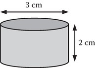
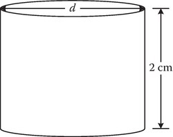
P4.1Find the three lowest resonant frequencies of the cylindrical cavity shown in the figure. Consider both TE and TM modes.
Note: After reviewing Section 3.7 on cylindrical wave guides and Sections 4.1 and 4.2 on rectangular cavities you can extend the theory to cylindrical cavities.
P4.2A circular cylindrical cavity excited in the TM011 mode appears to resonate at a frequency of 9.375 GHz. The cavity is made of aluminum (σ = 3.5 × 10⁷ S/m) walls and is of length 2 cm.
Find the diameter of the cavity.
If the cavity is completely filled with wet snow (dielectric constant = 3.5 − j0.1), what will be the new resonance frequency?
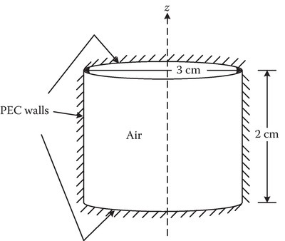
P4.3Find the resonant frequencies of the following modes of the cylindrical cavity shown in the figure.
TM212
TE222
P4.4Design a square-based cavity with height one-half (1/2) the width of the base to resonate at 1 GHz (a) when it is air-filled and (b) when it is polystyrene- filled. (c) Calculate the quality factor Q of the cavity if it is air-filled and the walls are made of copper.
P4.5In Section 4.3, we derived the expression for the Q of a cubic cavity for the TE101 mode. Do the same for TM111 mode.
Chapter 5
P5.1a.Write down the expression for ˜Fe in (5.23) for the lowest resonant frequency mode TMr101 of the spherical cavity. Use F101 as the mode constant.
b.Determine the expression for the electric and magnetic fields of this resonant mode.
c.What are the degenerate modes of this lowest resonant frequency mode? Write down the expression for ˜Fe of these degenerate modes.
P5.2Determine the next lowest resonant frequency of the spherical cavity. What are its degenerate modes? Write down the expressions for ˜Fe of these degenerate modes.
P5.3a.Design a spherical cavity (determine its radius a) with a difference of 1 GHz between its lowest resonant frequency and its next lowest resonant frequency. The medium in the cavity is air.
b.The radius a is reduced to half its size by using a nonmagnetic dielectric with the relative permittivity εr. Determine εr.
P5.4Repeat the calculations of P5.3, if you are restricted to TEr modes only.
P5.5Calculate Q of a spherical cavity of radius a =10 cm for the lowest resonant frequency.
P5.6Show that ejz=ejrcosθ=∑∞n=0jn(2n+1)jn(r)Pn(cosθ) (Harrington, p. 290).
P5.7Show that jn(r)=j−n2∫π0ejrcosθPn(cosθ)sinθdθ.
P5.8Prove the addition theorem for spherical Hankel functions:
where ξ is the angle between r and r′.
P5.9Assume a hemispherical cavity of radius a. Determine the dominant mode and the expression for its resonant frequency. Determine the Q of this cavity (P10.23, Balanis)
P5.10Consider a wedge consisting of two PEC plates of infinite extent, one described by ϕ = 0 and the other by ϕ = α. The field region is defined by, 0 < r < ∞, 0 < θ < ϕ, 0 < ϕ < α. (a) Describe its TEr modes. (b) TMr modes.
P5.11Convert the expression in (7.87) for the vector potential A of hertzian dipole into spherical Bessel function. Determine the E and H fields from this expression in terms of spherical Bessel functions and other functions (P10.1, Balanis).
Chapter 6
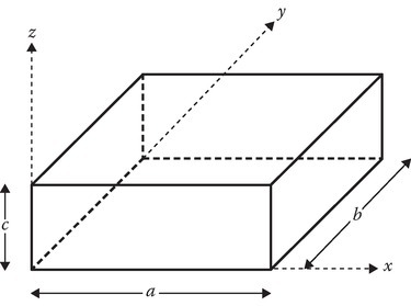
P6.1Consider a box having dimensions a × b × c in the x-, y-, z-directions, respectively. Choose the center of the rectangular coordinate system to be at one corner of the box so that the coordinates of all points in the box are positive.
The potential on the face of the box lying on the xy-plane is given by
The potential on the face of the box lying in the yz-plane is given by
The other four sides of the box are at zero potential. Find the potential at all points inside the box.
P6.2Consider a rectangular prism of width a in the x-direction and b in the y-direction with all four sides at zero potential extending from z = 0 to z = infinity. At z = 0, the cylinder has a cap with the following potential distribution:
Find V(x, y, z) within the prism.
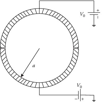
P6.3A cylindrical capacitor is shown in the figure below. Find the potential distribution inside and outside the capacitor.
P6.4Find a series for the potential inside the cylindrical region of figure below with end plates z = 0 and z = l at zero potential. The cylinder has a radius of a and is in two parts: From z = 0 to z = l/2 it is at potential V0 and z = l/2 to z = l, it is at potential −V0.

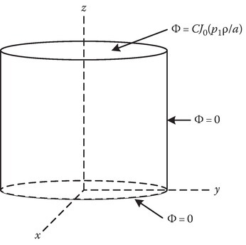
P6.5Suppose that the end plate at z = l of figure below is divided into insulated rings and connected to sources in such a way that the potential approximates a single J function of the radius given by
The end plate at z = 0 is at zero potential. Write the solution for Φ(ρ, z) at any point inside the cylindrical region.
P6.6In a region where the Laplace equation is satisfied, the potential can have neither a maximum nor a minimum. Prove this.
Consider a volume of free space bounded (enclosed) by a closed conducting surface at a potential 100 V. Can there be a point inside at 80 V? Or another point at 120 V? Can you find the voltage at the origin? Can you show that all points inside the closed surface have to be at 100 V? This is the principle of Faraday’s cage.
P6.7Find the electrostatic potential Φ at a general point P(x, y) in the region 0 < x < ∞, and 0 < y < b. The boundary potentials are shown in the figure.

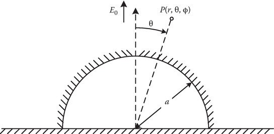
P6.8A conducting hemisphere is placed on a flat conducting infinite sheet, as shown in the figure. Before the hemisphere was introduced, the electric field everywhere above the sheet was normal to it and equal to E0. The radius of the sphere is a. The angle θ is measured from the normal to the sheet. The medium above the sheet is air. Assume the potential of the hemisphere and sheet to be zero. Find the potential everywhere above the sheet and the hemisphere. Find Φ(r, θ, ϕ). Note P1(cos θ) = cos θ, Pn(0) = 0 for n odd, and Pn(0)=(−1)n/21⋅3⋅5⋯(n−1)2⋅4⋅6⋯n for n even.
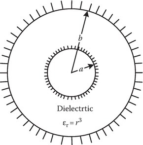
P6.9A spherical capacitor is filled with an inhomogeneous dielectric of dielectric constant εr(r) = r3. Determine its capacitance.
P6.10Suppose the end plate at z = 1 of the figure is at a potential
and the end plate at z = 0 is at a potential,
Here p1 and p3 are the first and third zeros of the Bessel function J0. The surface ρ = a is at zero potential. Write the solution for Φ(ρ, z) at any point inside the cylindrical region.

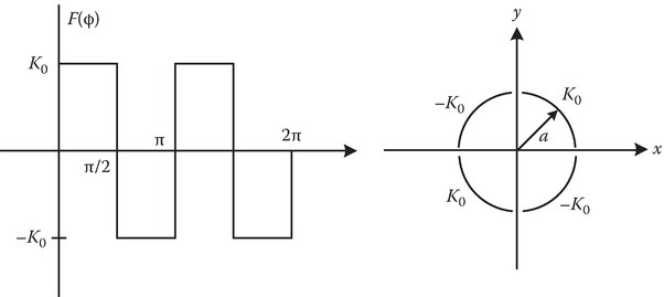
P6.11In this two-dimensional problem, the potential on the circle ρ = a varies as
Determine the potential at the point P (a/2,60°).

P6.12In a circular cylindrical region a < ρ < b as shown in the figure, the electrostatic potential V satisfies Laplace’s equation. The boundary conditions are:
Given that b = 2a and V(3a/2, 90°) = −4 V, find a.

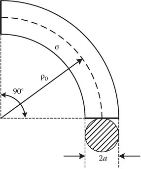
P6.13A piece of material of conductivity σ, of circular cross section 2a, is shown in the figure. Find the resistance R between the faces A (horizontal line) and B (vertical line). Show that the approximate value of
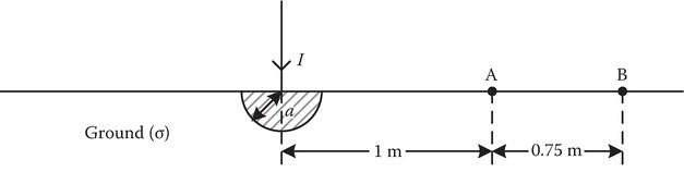
P6.14A hemispherical electrode of very high conductivity is buried in poorly conducting earth as shown in the figure below. Determine the resistance of such a grounding system. Given the following data (σ = 10−2, I = 1000 A), find the potential difference between A and B. If A and B represent the feet of a man would you consider the voltage dangerously high?
P6.15On the cylindrical surface ρ = a, a surface current K=F(ϕ)ˆz flows. Find B at all points. Use the vector magnetic potential A to solve the problem.
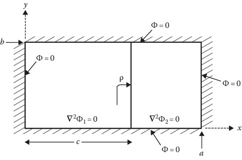
P6.16Determine the potential in the regions:
Region 1: 0 < x < c and 0 < y < b,
Region 2: c < x < a and 0 < y < b.
x = c is a sheet of surface charge of constant surface charge density ρs (C/m2).
P6.17a.In a region R bounded by a closed surface S, the potential V satisfies Laplace equation ∇2V = 0. Show that V can have neither a maximum nor a minimum in the region R.
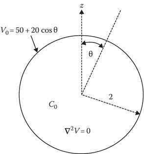
b.Refer to the figure below. Given that the potential V on the surface S (sphere of radius r = 2) is Vs = 50 + 20 cos θ. Show that we can put bounds for the potential V at a point C inside the sphere: that is, Vmin < VC < Vmax. Determine Vmin and Vmax.
c.It may be shown that the solution to the Laplace equation in spherical coordinates is given by
Here V is assumed to be independent of ϕ and r < 2. Pm (cos θ) is the symbol for Legendre polynomials and some of these are given in Table 5.3.
Determine VC, where C has spherical coordinates r = 0.5, θ = 30°, and ϕ = 120.
P6.18Consider a box having dimensions a × b × c in the x-, y-, and z-directions, respectively. The medium inside the box is free space and the potential on the faces of the box satisfy the following equations:
Find Φ(x, y, z) in the volume region: 0 < x < a, 0 < y < b, 0 < z < c.
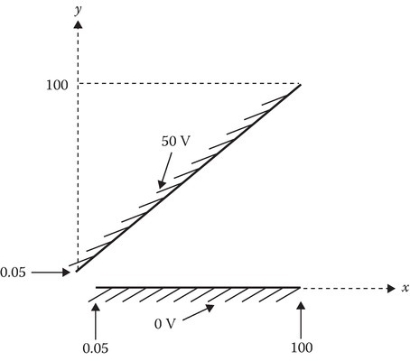
P6.19The figure shows the cross section in the x-y plane. Determine the potential at the point P(2, 1, 3). The conductors extend from −80 < z < 80. One conductor is at 0 V and the other is at 50 V. They are separated by a small insulating gap as shown in the figure. Use a suitable approximation.
P6.20This problem is a spherical-coordinate variation of the problem in P6.19.
A plane conductor (x–y plane) is at zero volts. The conducting surface of a cone making 45° with z axis (θ = 45°, in spherical coordinates) is at 50 volts. Determine the potential at P(1,2,3); the numbers in the parenthesis are the Cartesian coordinates. Assume there is a small insulating gap at the tip of the cone and the origin.
Chapter 7
P7.1Derive Equation 7.8.
P7.2Show that the group velocity in an empty waveguide is given by
P7.3Derive Equation 7.30.
P7.4Let ˜ˉG=ˆzG(ρ) and ∇2G+k20G=δ(ˉρ−ˉρ′).
Find the one-dimensional Green’s function G(ˉρ,ˉρ′).
P7.5Determine Green’s function of the differential equation
subject to the boundary conditions
P7.6Determine Green’s function G for the two cases given below:
d3Gdx3=δ(x−x′), the domain of x is 0 < x < L
G=0,x=0,dGdx|x=0=0,G(L)=0.d2Gdx2+k2G=δ(x−x′), the domain of x is unbounded, that is, −∞ < x < ∞
P7.7Refer to Section 7.3 and Figure P7.8.
Find the ABCD parameters and S parameter. Utilize the results to find the input reflection coefficient if the output is matched.
P7.8Given
Find ABCD parameters. Utilize the results to find the input reflection coefficient if the output is matched (Figure P7.8).
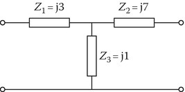
FIGURE P7.8
P7.9Consider the propagation of a p wave in a dielectric layer of width d as shown. Find the ABCD parameters (consider the positive-going and negative-going waves in the layer).
P7.10Repeat the above problem for an s wave.
P7.11Figure shows the circuit equivalent of a section Δz of a transmission line.
Derive the partial differential equation for the voltage V(z, t).
Assume V(z, t) = V0 ej(ωt−kz), find the relation between ω and k.
Draw the ω–k diagram and label it in terms of
ω1=1√L′1C′1,ω2=1√L′2C′2.
Suppose the above transmission line is to act as a filter, rejecting the frequencies of 5–10 GHz. Choose reasonable values for L′1, L′2, C′1, and C′2 that will accomplish this goal.
For these chosen values, determine the group velocity and phase velocity when the frequency of the signal is 12 GHz.
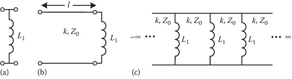
P7.12a.Find the ABCD parameters of the lumped inductor L1 of impedance Z1 shown in the figure.
b.A lossless air transmission line of length l and wave number k has a characteristic impedance of Z0 ohms. This line is loaded with the inductor as shown in figure b. Determine the ABCD parameters of this system.
c.The system shown in figure b is a unit cell of a periodic system with infinite number of cells to the left and the right as shown in figure c.
Obtain the dispersion relation of the periodic system relating the propagation constant β of the periodic system with the parameters of the unit cell.
d.Determine the first pass band of the system. Express your answer in the form ω1 < ω < ω2. Find ω1 and ω2.
P7.13a.Find the ABCD parameters of the lumped capacitor element C1 of admittance Y1 shown in figure a below.
b.A lossless air transmission line of length l and wave number k has a characteristic admittance of Y0 = 1/Z0. This line is loaded with the capacitor as shown in figure b. Determine the ABCD parameters of this system.
c.The system shown in Figure 7.13b is a unit cell of a periodic system with infinite number of cells to the left and the right as shown in Figure 7.13c. Obtain the dispersion relation of the periodic system relating the propagation constant β of the periodic system with the parameters of the unit cell.

P7.14A 1.5-m long dipole antenna is excited by a harmonic current of amplitude 8 A and frequency f = 1.5 MHz. Find the time-averaged power density radiated by the dipole at a distance of 5 km in a direction 60 degrees from the axis of the dipole.
P7.15A half-wavelength center-fed dipole is used as an antenna at 100 MHz. The current amplitude I0 is 10 A. The dipole lies along z-axis.
Determine the z component of the vector phasor ˜E at the following points described in spherical coordinates: (i) R = 100, θ = 90 degrees, ϕ = 90 degrees (ii) R = 100, θ = 30 degrees, ϕ = 90 degrees.
The antenna wire is made of copper (σ = 5.8 × 10⁷ S/m) and has a radius a = 0.4 mm.
Calculate the radiation resistance and the radiation efficiency of the dipole antenna.
P7.16A half-wavelength center-fed dipole is used as an antenna at 100 MHz. The current amplitude I0 is 10 A. The dipole lies along z-axis.
Determine the z component of the vector phasor ˜E at the point P described in spherical coordinates: R = 100, θ = 60 degrees, ϕ = 90 degrees.
The center of a vertical (parallel to z-axis) receiving antenna 3 cm long is located at the point P. Calculate the open circuit voltage ˜Voc induced on the receiving antenna. Assume the medium in which the antennas are located is air.
P7.17Derive the cylindrical wave transformations given by (7.124a) and (7.124b).
P7.18Derive the cylindrical wave transformations given by (7.125a) and (7.125b).
P7.19Derive the cylindrical wave transformations given by (7.126).
Chapter 8
P8.1Simple metal like sodium has a plasma frequency of ωp = 2 × 10¹⁶ rad/s and collision frequency of ν = 2 × 10¹³ rad/s. Plot α, β, nR, and nI as in Figure 8.6. Mark conducting, cutoff, and dielectric regions.
P8.2Let the plasma medium shown in Figure 8.7 have a collision frequency ν (rad/s). Determine the time rate of decay of plasma oscillations given by Equation 8.41.
P8.3Show that the group velocity in an unbounded plasma is given by
P8.4Find the cutoff frequency of a waveguide in which the medium is a plasma of frequency fp. Let fc be the cutoff frequency of the empty waveguide.
P8.5The intense friction around a space vehicle re-entering the atmosphere generates a plasma sheath which is 1 m thick and is characterized by an electron density of N0 = 1013/cm3, and the collision frequency ν = 1011/s. Calculate the power loss in decibels if the signal frequency f is equal to (a) 30 GHz, (b) 300 GHz, and (c) 350 GHz.
P8.6The dielectric function for water is given below.
where ε∞ is the infinite frequency relative permittivity, εs is the static relative permittivity at zero frequency, and t0 is the relaxation time.
Determine the (a) intrinsic impedance ηC, (b) phase velocity, and (c) group velocity at frequencies:
5 GHz,
20 GHz,
50 GHz,
Assume εs = 81, ε∞ = 1.8, t0 = 9.4 × 10⁻¹² s.
P8.7Calculate and plot the effective dielectric constant of a mixture of two media with εr1 = 2 and εr2 = 3 as a function of f, the fractional volume of inclusions of a material of dielectric constant εr2.
P8.8A super conductor thin film of thickness d where d is comparable to the London penetration depth λL is excited as follows:
Assume DC excitation and d << w.
Find the expression for H in the region −d/2 < z < d/2.
Find the expression for J the region −d/2 < z < d/2.

P8.9Derive Equations 8.124 and 8.130.
P8.10Starting from Equation 8.135, obtain Equation 8.141.
P8.11A superconducting microstrip has the following parameters:
Normal conductivity σn = 0.5 × 10⁶ (S/m).
London penetration depth λL = 0.14 × 10⁻⁶ m.
Calculate the surface resistance Rs of the superconducting strip and compare it with the surface resistance if it were a normal conductor with the value of σn given above. Take the frequency f = 10 GHz.
P8.12a.Refer to Figure 4.1. A rectangular cavity of square cross section (a = b) and height h utilizing the simple TE101 mode is to be designed for a millimeter-wave electron device for operation at fr = 0.2 THz. Height of the cavity must be kept small (take h = 1 mm) to minimize electron transit time. The medium in the cavity is air. The walls are made of copper σ = 5.8 × 10⁷ s/m. Design the cavity by calculating a, also calculate the quality factor Q of the cavity.
b.Suppose the walls of the cavity are made of superconducting material with the following parameters:
Normal conductivity σn = 5 × 10⁶ (S/m);
London penetration depth λL = 0.5 × 10⁻⁷ m.
Determine the Q of the cavity.
P8.13In the equivalent circuit of a transmission line (for a length Δz) shown in the figure, assume LR = CR = LL = CL = 1.
Sketch the ω–k diagram, for k varying from −∞ to ∞.
If ω = 0.8, determine (i) phase velocity vp, (ii) group velocity vg, and (iii) wavelength λ.
Repeat (b) if ω = 1.
Repeat (b) if ω = 1.1.
P8.14Determine the wave number kc and the wave impedance ηc for the case of propagation of L wave in a chiral medium.
P8.15A linearly polarized wave can be decomposed into circularly polarized waves, for example, ˆxE0=E0/2(ˆx+jˆy)+E0/2(ˆx−jˆy). This kind of decomposition could be useful in solving the problem. A chiral medium whose constitutive relations are given by Equations 8.174 and 8.175 has the following parameters at 10 GHz: ε = ε0εr, εr = 2, μ = μ0μr, μr = 1, ξc = 0.005. The electric field of a plane wave, propagating in the positive z-direction in this medium, is linearly polarized in x-direction at z = 0 and is given by E=ˆx3cos(2π×1010t)V/m.
Determine the electric field in this medium at z = 2 × 10⁻².
Determine the polarization of the wave and sketch it in the z = 2 × 10⁻² plane like one of the sketches in Figure 2.6.
Determine the magnetic field H of the wave at z = 2 × 10⁻².
P8.16a.Draw the ω–k diagram for an unbounded periodic media consisting of alternating layers of chiral media. Assume the following values for the parameters of the layers in a unit cell:
First layer: ε1 = 2ε0, μ1 = μ0, ξc1 = 10−3, L1 = L0 = 3 cm.
Second layer: ε2 = 3ε0, μ2 = μ0, ξc2 = −4ξc1, L2 = 2L0.
b.Determine the location of the center of the first stop band. Also, determine the bandwidth of this stop band.
c.Same data as above but ξc1 = 0, that is, the layers are not chiral. Determine the first stop band and its width.
Chapter 9
P9.1Let εp(z, ω) is given by
Show that the solution of Equation 9.15 in the two regions given below may be written as
where I, R, T, and A are constants and k1=k0√ε1 and k2=k0√ε2. Give physical reasons for setting A = 0. Note that if I = 1, R and T give the reflection and transmission coefficients. Assume the waves are propagating along z-axis.
P9.2Find an analytical expression for |R|2 if L = 0 in previous Equations P2.2 and P2.3.
P9.3Light of wavelength 0.633 μm is incident from air on to an air–aluminum interface. Take the dielectric constant of aluminum at 0.633 μm as εr = −60.56 − j24.86.
Plot reflectivity (ρ) versus θi of a s wave, where θi is the angle of incidence.
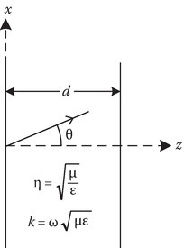
P9.4The geometry is given in Figure P9.4.
Find the reflectivitfy of a p-wave in free space incident on the metal at an angle of incidence of 45° when:
ω = 8.2 × 10¹⁵ rad/s.
ω=(1.1√2)8.2×10¹⁵rad/s.
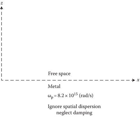
FIGURE P9.4
P9.5The geometry is given in Figure P9.4.
Investigate the propagation of a surface plasmon TM on this interface at ω = 4.1 × 10¹⁵ rad/s.
Determine the phase velocity of the surface charge wave on the interface.
Determine the distance, in meters, in which the z-component of the electric field in free space reaches 0.3679 (= e−1) of its value at the interface.
Determine the distance, in meters, in which the z-component of the electric field in metal reaches 0.3679 (= e−1) of its value at the interface.
P9.6The geometry is given in Figure P9.4.
Investigate the propagation of a surface plasmon TM on this interface at ω = 9.84 × 10¹⁵ rad/s.
Determine the phase velocity of the surface charge wave on the interface.
Determine the distance, in meters, in which the z-component of the electric field in free space reaches 0.3679 (= e−1) of its value at the interface.
Determine the distance, in meters, in which the z-component of the electric field in metal reaches 0.3679 (= e−1) of its value at the interface.
P9.7In this problem, we investigate the nature of the solution of Equation 9.15 in the domain 0 < z < L.
By introducing a new variable ξ=k20εP(z,ω), show that Equation 9.15 may be transformed to
where
Note that the solution of Equation P9.6 may be written in terms of Airy function Ai and Bi:
P9.8Determine the reflection coefficient R and plot the power reflection coefficient |R|2 versus L. Take ε1 = (4/3)2 and ε2 = 1. These data approximate the water–air interface at optical frequencies. Assume that the dielectric function is a linear profile given by
P9.9Discuss the possibility of having a TE surface wave mode at a metal–vacuum interface.
P9.10Derive the dispersion relation and draw the ω–β diagram of an unbounded periodic media consisting of alternating layers of dielectric layers. Assume the following values for the parameters of the layers in a unit cell
First layer: ε1 = 2ε0, μ1 = μ0, L1 = L0 = 3 cm.
Second layer: ε2 = 3ε0, μ2 = μ0, L2 = 2L0.
Determine the location of the center of the first stop band. Also, determine the bandwidth of this stop band.
P9.11The cutoff frequency of a waveguide with free-space medium is 4 GHz. The medium is a loss-free plasma of plasma frequency 3 GHz. The signal frequency is 6 GHz. Determine the b. Determine the group velocity.
P9.12Obtain (9.127) using ABCD parameter technique of Section 7.4.
Chapter 11
P11.1Derive Equation 11.25.
P11.2Show that Equations 11.25 and 11.28 are the same.
P11.3Given f = 2.8 GHz and B0 = 0.3 T, find the electron density of the plasma at which the L wave has a cutoff.
P11.4Given f = 10 GHz and B0 = 0.3 T, find the electron density of the plasma at which the R wave has a cutoff.
P11.5Faraday rotation of an 8 mm wavelength microwave beam in a uniform plasma in a 0.1 T magnetic field is measured. The plane of polarization is found to be rotated by 90° after traversing 1 m of plasma. What is the electron density in the plasma?
P11.6
For a whistler mode, that is, ω << ωp, ω << ωb, show that the group velocity is given approximately by
(P11.1)vg≈2c√ωωbωp.Assume that due to lighting, signals in the frequency range of 1–10 kHz are generated. If these signals are guided from one hemisphere to the other hemisphere of the Earth along Earth’s magnetic field over a path length of 5000 km, calculate the travel time of the signals as a function of frequency. Take the following representative values for the parameters: fp = 0.5 MHz and fb = 1.5 MHz.
P11.7Figure 11.1 shows the variation of the dielectric constant with frequency for the case of R wave propagation. The branch between 0 and ωb is the whistler mode. Obtain the frequency ω at which the εpR is minimum. What is the minimum value of εpR at this frequency?
P11.8A right circularly polarized electromagnetic wave of frequency f0 = 60 Hz is propagating in the z-direction in the metal potassium, at a very low temperature of a few degrees Kelvin, in the presence of a z-directed static magnetic flux density field B0.
Determine (a) the phase velocity and (b) wavelength of the electromagnetic wave in the metal.
Assume that electron density N0 of the metal is such that ωp = 1016 rad/s.
Assume that B0 value is such that the electron gyrofrequency ωb = 1012 rad/s.
Assume that the collision frequency ν is negligible.
The calculations become simple if approximations are made based on the inequalities mentioned above. Relate the specification of a very low temperature to one of the assumptions given.
P11.9Derive Equations 11.52 and 11.54.
P11.10Derive Equation 11.56, Equation 11.57 and Equation 11.58.
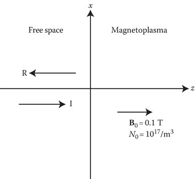
P11.11An x-polarized plane wave in free space of frequency f = 2 GHz is incident normally on a magnetoplasma. The electron density of the plasma and the strength and direction of the static magnetic field B0 of the magnetoplasma are shown in the figure. Determine the power reflection coefficient.
P11.12For a whistler mode, where the electron gyrofrequency ωb is only slightly more than the source frequency ω0 and ω2p is such that the inequality
is satisfied, show that the relative permittivity will be quite high so close to resonance. Obtain an expression for the group velocity. Calculate the group velocity if fb = 10.009 GHz, fp= 30 GHz, f0= 10 GHz.
P11.13For the mode and the inequalities described in P11.12, determine the attenuation constant α, if the collision frequency is ν rad/sec. Also determine the damping distance constant zp and the damping time constant tp.
P11.14For the mode and the inequalities described in P11.6, determine, α, zp, and tp.
P11.15Medium 1 in which the incident plane wave is traveling in the z-direction, is the half-space z < 0. The electric field of the incident wave is in x-direction. The frequency f = 6 GHz.
Medium 2 is a magnetoplasma with the parameters fb = 3 GHz and fp = 4 GHz.
Determine the power reflection coefficient in each of the cases given below
Case a: the static magnetic field is in x-direction
Case b: the static magnetic field is in y-direction.
Chapter 12
P12.1Biaxial crystal mica has the principal refractive indices nx = 1.552, ny = 1.582, and nz = 1.588. The electric field of a wave propagating in the x-direction at x = 0 is given by
Determine E at x = 1 m.
Determine H at x = 1 m.
P12.2Consider rutile (positive uniaxial crystal) with n0 = 2.616 and ne = 2.903. Let the optic axis of the crystal be perpendicular to the paper. If θI = 30°, determine the transmission angles θto and θte of the doubly refracted wave.

P12.3Crystal is rutile (data as in P12.2) but the optic axis of the crystal is along the x-axis. Determine the transmission angles θto and θte.
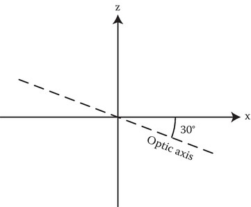
P12.4Crystal is rutile (data as in P12.2). The optic axis is in the x–z-plane making an angle of −30° with the x-axis as shown in the figure. Determine the transmission angles θto and θte.
P12.5Consider calcite (negative uniaxial crystal) with n0 = 1.658 and ne = 1.486. Let the optic axis of the crystal be perpendicular to the paper. If θi = 30°, determine the transmission angles θto and θte of the doubly refracted wave. (The figure is same as the figure of Problem P12.2 except the upper medium is calcite.)
P12.6Consider calcite (negative uniaxial crystal) with n0 = 1.658 and ne = 1.486. The optic axis of the crystal is along the x-axis. Determine the transmission angles θto and θte. (The figure is same as the figure of Problem P12.2 except the upper medium is calcite).
P12.7Consider calcite (negative uniaxial crystal) with n0 = 1.658 and ne = 1.486. The optic axis is in the x–z-plane making an angle of −30° with the x-axis as shown in the figure above. Determine the transmission angles θto and θte.
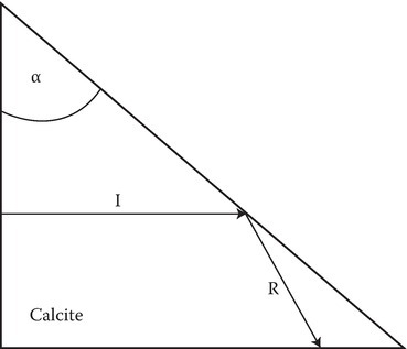
P12.8Consider a light beam incident on the plane boundary from the inside of a calcite crystal (n0 = 1.658 and ne = 1.486). Suppose the optic axis of the crystal is normal to the plane of incidence. Find the range of apex angles α so that the ordinary wave is totally reflected.
P12.9A p wave is propagating in the x–z-plane in an uniaxial dielectric crystal (optic axis along the z-axis) whose constitutive relations are given by
For an x–z-plane of propagation shown in the figure of Problem P12.8, the exponential phase factor has the form
Determine q in terms of n0, ne, and S.
A p wave in free space is incident on the uniaxial crystal as shown in the figure. Determine the relation between θt, θi, n0, and ne.
If n0 = ne = n = 1.5, θi = 30°, determine θt.
(Note: The p wave has ˜Ex, ˜Ez, ˜Hy components only.)

Chapter 13
P13.1Assume the data given in Example 13.8 except that the load end is not matched and RL = ∞. Sketch the load voltage.
P13.2Give sketches of VS(t) for Example 13.8 and Problem 13.1 above.
P13.3Suppose the voltage wave form V(0, t) described below is observed at the sending end of a 50 Ω transmission line in response to a step voltage introduced by a generator with Vg = 15 V and an unknown series resistance Rg.
The line is 1.2 km in length and its velocity of propagation 108 m/s, and it is terminated in a load of ZL = 75 Ω.
Determine Rg and the shunt resistance Rf and the location of the fault responsible for the fault [1].
P13.4TDR is useful in determining the inductance of a bonding wire between two microstrip interconnects. Reference 2 illustrates a suitable theory to facilitate such a measurement. Formulate the problem and explain how the inductance can be measured.
The device is called Time Domain Reflectometer. Its principle is illustrated through the example.
P13.5Show that the solution of (13.96) and transformation back to the lab frame in z, t gives (13.86).
P13.6Show that the x component of (13.172) can be written as (13.173).
P13.7Show that if L and hence H is not an explicit function of t, Equation 13.184 is satisfied.
P13.8The circuit representation of a differential length of a nonlinear transmission line with dispersion is shown in Figure 13.15. Show that the voltage of the transmission line satisfies (13.83) when the nonlinear capacitance is given by (13.82).
P13.9Derive the dispersion equation (13.84), when C′N=0 in (13.83).
P13.10In Section 13.7 EMP1, suppose G is a function of the voltage across the capacitor (G = G0V) and the current source has a double exponential variation given below:
Determine the voltage across the capacitor.
P13.11Show that the LHS of (13.249) can be combined into one term given by the LHS of (13.248).
P13.12Starting from (13.300), fill in the steps leading to (13.304).
P13.13Show that the RMS velocity, using Maxwellian distribution, is given by (13.318).
P13.14Derive (13.334) and prove the assertion that the force due to wave magnetic field can be neglected).
P13.15Derive (13.336).
P13.16Show that (13.339) reduces to (13.340) for the special case of the collision frequency ν independent of the velocity variable v.
P13.17See Figure P13.17a. A uniform plane wave traveling in free space to the right along z-axis has an electric field, EI=E0ej(ω0t−k0z)ˆax.
See Figure P13.17b. At t = 0 the whole medium is suddenly turned into a dielectric of dielectric constant εR. Assume that this sudden switching of the medium gives rise to a reflected wave (left-going) and transmitted wave (right-going) whose electric fields are written as:
Determine the relation between ωR and kR; ωT and kT.
Also determine ωR, kR, ωT and kT in terms of ω0, k0 and εR.
Assume that the suddenly switched dielectric medium is a plasma of plasma frequency 4 GHz. If ω0 is 3 GHz determine ωR and ωT.
Note: The dielectric constant of plasma is:
where ωp is the angular plasma frequency in rad/s and ω is the angular signal frequency in rad/s.

FIGURE P13.17
(a) Free space and (b) dielectric (εR).
P13.18Let ω1 be the frequency of a propagating wave in a plasma medium of plasma frequency ωp1. At t = 0, the electron density suddenly drops. Let ωp = ωp2 for t > 0, where ωp2 < ωp1. Find the new frequencies and fields of all the modes generated by the switching action.
Chapter 14
P14.1Refer to Figure 14.1. Determine the frequency of the reflected wave for normal incidence on a moving mirror. If the reflected wave frequency is (1 + 10−7) times the incident wave frequency, determine the velocity of the mirror. Is the mirror moving towards the source of EM radiation or away from the radiation.
P14.2Obtain (14.26).
P14.3What is the relation between angles α and α′? What is the value of α when the velocity v tends to c [1].
P14.4Two events occur at the same place in the laboratory at an interval of 2 s. What is the spatial distance between these two events in a moving frame with respect to which the events occur 5 s apart, and what is the relative speed of the moving and laboratory frames? [1]
P14.5A physicist, to avoid fine for driving through a red light, argues that the red light looked to him as green from his moving vehicle. The judge fined him $ 1 for every kilometer of speed in excess of 50 km/h. What is the fine? Wavelength: Green: 0.53 microns, Red: 0.65 microns [1].
P14.6Refer to Figure 14.4. If S′ is moving at a uniform velocity of 0.35 c in the z-direction with reference to S, determine the complex angle ψ [1].
P14.7aA linear accelerator accelerates the electrons to the full energy of 30 GeV. Calculate the mass of this electron [1].
P14.7bA proton has a kinetic energy of 450 million electron volts. Find the mass and velocity [1].
P14.8A charged parallel plate capacitor moves with a velocity v in a direction normal to the plates. The capacitor plates have an area A and are separated by the distance s. The electric field is E′ in the direction of the capacitor movement. Find V, vector potential A, and the fields E, B with respect to a stationary reference frame [1].
P14.9Show that Equation 14.76 is included in the four dimensional curl equation (14.77).
P14.10Determine the power reflection coefficient for normal incidence (wave propagating along z direction) of a plane wave on a moving dielectric half space moving along z direction with a velocity v0=ˆzv0=ˆzβc. Assume n = 2 is the refractive index of the dielectric measured in the rest frame of the moving dielectric. Sketch ρ (power reflection coefficient for the entire range of β from −1 to +1.
Appendix 1B
P1B.1A conducting filament extends from z = −5 to z = 5 m on the z-axis in free space and carries a current I = 4t in the ˆz-direction. Find and sketch A(t) at (0, 0, 10) for −0.1 ≤ t ≤ 0.1 μs.
P1B.2Given the retarded potentials Φ=x−ct,A=(x/c−t)ˆx, where c=1/√μ0ε0.
Show that ∇ ∙ A = −μ0ε0(∂Φ/∂t).
Find B, H, E, and D.
Show that these results satisfy Maxwell’s equations in free space.
P1B.3Given Ãz = C sin (πx/a) sin (πy/b) cos(πz/d), find the corresponding electric and magnetic field phasors. Find the electric and magnetic fields as a function of time.
P1B.4Given Ãϕ = CJ1 (kcr) e−jβz, find the electric and magnetic fields.
P1B.5Given that the vector potential in free space is given by
determine
Vector magnetic field phasor ˜ˉH
Vector electric field phasor ˜ˉE
Time-averaged power density at the point P (1, 2, 3).
A PEC plate is placed at z = 0. Determine the surface charge density ˜ρs on the plate.
A PEC plate is placed at z = 0. Determine the surface current density ˜ˉJs.
Appendix 2C
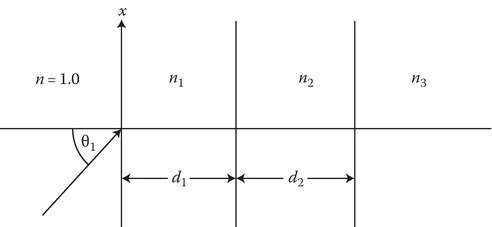
P2C.1An s-wave with free space wavelength λ0 = 3 cm is incident on the dielectric layers as shown in the figure. Calculate the reflection and transmission coefficients. n1 = 1.5, n2 = 2.0, n3 = 2.5, d1 = 1 cm, d2 = 1.5 cm, θi = 30°
Appendix 7A
P7A.1a.The cross section of a grounded cylindrical pipe is shown in the figure below. Show that the three-dimensional Green’s function G, satisfying Dirichlet boundary conditions on the surfaces ϕ = ϕ1, ϕ = ϕ2 and ρ = b is as given in Equation P2.1.
b.Given ϕ1 = 30° and ϕ2 = 120°, determine S in terms of m.
c.Determine (i) kS1 and (ii) kS2, if b = 2 and m = 1.

0 < ρ < b.
Note:
where λk is a root of Jn(λkc) = 0.
Appendix 13A
P13A.1Derive (13A.2).
P13A.2Obtain (14B.1a) and (14B.1b).
P13A.3Determine the pressure on the interface of two dielectrics due to electric fields with normal as well as tangential components. Express it in terms of the permittivities of the two media and the field components in medium 1.
P13A.4Determine the pressure on the interface of two magnetic media due to magnetic fields with normal as well as tangential components. Express it in terms of the permeabilities of the two media and the field components in medium 1.
Appendix 13B
P13B.1Use (1B.10) to derive the Biot-savart law for computing the B-field at a field point P due to a differential filamentary current element IΔL at the source point S.