
It is possible to change an object's surface visibility based on its distance from the camera. You can also get the distance to the next surface underneath it or behind it, even where it varies pixel for pixel. Some kinds of netted curtain fabric exhibit this effect; where the fabric is close to the window it is see through, and where it's further off the surface, it isn't. In a game environment, a fringe of transparency created by a DepthBiasedAlpha node is often used at the converging edge of water and land so that some of the shore is visible under shallow water, while the water opacity increases further out. It is also possible to create holographic or scanning effects using this node. In this recipe and the next we'll do both, creating a murky pool and a passageway scanner.
Coverage of DepthBiasedAlpha and other depth based Material nodes can be found at http://udn.epicgames.com/Three/MaterialsCompendium.html. Look up SceneDepth and PixelDepth too.
Open the scene Packt_09_DepthBiased_Start.UDK. You will see a large pool and an enclosed passageway, both filled with objects. The objects are there to help us get a sense of the changes in depth or distance in the scene. In this recipe, what we're interested is the Material on the surface of the pool.
- In the Content Browser, create a new Material: Yourfolder.Material.PoolDepth_mat. Apply it to the surface of the pool, which is a Mover animated to go up and down by a Kismet Matinee.
- Open your new Material in the Material Editor. Set its PreviewMaterial properties so Lighting Model is MLM_Unlit since it won't require scene lighting, and set the Blend Mode to BLEND_Translucent. That means it can handle variable transparency. Turn on Two Sided also, which means if you have the Material on a plane it will show on both sides.
- Right-click and choose Depth | New DepthBiasedAlpha and in its properties set the Bias Scale to 100. The Bias Scale value determines the extent of the alpha based on the distance between two surfaces. Hook up the DepthBiasedAlpha into the Opacity channel of the Material.
- Right-click and choose Utility | New ConstantClamp and hook this up into the DepthBiasedAlpha input. Set the Min value to 0.2 and the Max value to 0.95. Again, these values are fairly touchy, and it would be good at the end of the procedure to experiment with the effect of changing them.
- Hold L and click to add a Lerp. Hook this up to the ConstantClamp input. Hold 1 and click to add a Constant and then add another. Set the first to R = 0.5, name it
MINand then hook it up to the A nub of the Lerp. Set the second to R = 1.5, name itMAXand then hook it up to the B nub of the Lerp. Once again, the values entered here make a big difference to the final result. What these will finally control is the wideness of the blending at the surface. Hold D and click to add a Math | New Divide, and hook it into the Alpha input of the Lerp. - Hold 1 and click to add a Constant, name it Depth, and set R to 1024. This value determines the overall depth of the water, as a scalar value. Varying this, the Min and Max, as well as the Bias Scale affects the look of the transparency. Hook the Constant Depth to the B nub of the Divide.
- Right-click and choose Math | New Subtract, then hook it to the A nub of the Divide. Right-click and choose Depth | New DestDepth, then choose Depth | New PixelDepth. The DestDepth hooks into the A nub of the Subtract, and the PixelDepth hooks into the B nub of the Subtract.
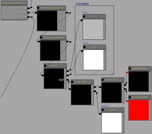
- Essentially that deals with the Opacity for the Material. The DestDepth node handles the depth from the camera to the nearest surface behind this Material (think of water and the bottom of the pool). The PixelDepth handles the depth from the camera to the surface. Subtracting PixelDepth from DestDepth gives us the depth of the water at every point.
- If you compile the Material, then build and PIE you should notice the water is a foggy black and static. Since the
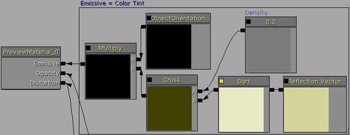
Lighting Modelis set to MLM_Unlit, it needs color, reflectivity, movement, and highlights to be driven through the other Material channels, such as a Distortion animation, and an Emissive tint. - There are many ways to proceed from here, so take this solution with a pinch of salt. Right-click in the Material Editor and choose Vector | New ReflectionVector. Right-click again and choose Math | New SquareRoot (Sqrt). Add a Constant, name it Density, and set its R value to 0.2. Right-click and add a Math | New CrossProduct (Cross) and hook up the Constant Density to its A nub and the ReflectionVector to its B nub.
- Right-click, choose Coordinates | New ObjectOrientation, then hold M and click to add a Multiply. Connect the ObjectOrientation to nub A of the Multiply, and connect the Cross to nub B. Hook up the Multiply to the Material's Emissive channel. This will allow you to produce a color tint for the water.
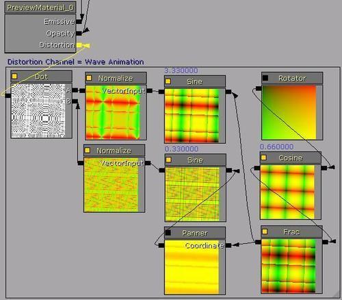
- Now for the Distortion of the surface, so we can ripple the water. There is a great deal of room to alter the values provided here. Right-click and add a Coordinates | New Rotator. Set its Center X property to 1.0, its Center Y property to 0.0, and its Speed property to 0.03 or thereabouts.
- Hook this up to a Math | New Cosine, and set the Period property of the Cosine to 0.66. Hook up the Cosine to a Math | New Frac.
- Hold P and click to add a Panner, and then set its Speed X property to 0.03 and its Speed Y property to 0.05. These values determine the speed of the texture across the water. It produces a sliding effect rather than a rippling effect.
- Right-click and choose Math | New Sine. A Sine is what adds a wave-like property to the pattern. Add another, and hook up the output of the Panner to it. For the second hook up the output of the Frac to it. Also hook up the Frac to the Panner node's input. The first Sine should have a Period of 0.33 and the other one a Period of 3.33 (or thereabouts). For each Sine, hook its output to a separate Normalize node (hold N and click). The period of the Sine creates an amplitude like effect in the wave.
- Right-click and add a Math | New DotProduct. A DotProduct creates a Falloff effect. Check out the example at http://udn.epicgames.com/Three/MaterialsCompendium.html#DotProduct.
- Feed one Normalized Sine into the A nub of the DotProduct and the other into the B nub. Connect the DotProduct output into the Distortion channel of the Material. These changes break up the ripple so it doesn't appear too uniform. Compile and check that the surface of the water is now rippling.
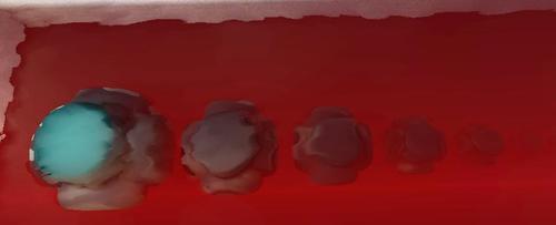
- If you start to vary the MIN and MAX Constant nodes you will notice that as you range up the values the apparent thickness of the water will change, and the apparent depth, and the apparent tilt of the water fog near the camera (since it's driven by PixelDepth), as in the next screenshot. The effect is actually best used from directly above the water so you'd expect to see it in a top down strategy game rather than a first person shooter.
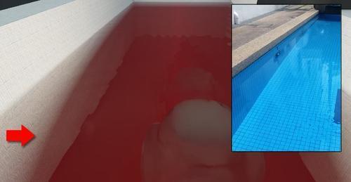
- At first I considered the curving tilt to be visually unpleasant and tried to fix it. Then I noticed a similar real-world effect, shown here, which is caused by refraction of the water. UDK doesn't even attempt to calculate refraction for transparent surfaces based on their Material, so maybe there's something here to chew on for those who ponder such problems.
- Compile and experiment with the value changes to see the range of looks the DepthBiasedAlpha network can produce. An example is provided: Packt_09_DepthBiased_DEMO.UDK.