
To start the Cylinder command, you can type the word CYLINDER (or just type CYL) and then press Enter, or you can click on the Cylinder button found in the Create panel in the 3D Basics workspace. If you are using the 3D Modeling workspace, you will find the Cylinder button in the Modeling panel under the Home tab, or in the Primitive panel under the Solid tab, as shown in the following screenshot:

To create a cylinder using the default settings, perform the following steps:
- Choose a location and click to specify the center point of the cylinder base.
- Move the mouse and click to specify the radius of the cylinder. Alternatively, you can use the keyboard to enter the radius value and then press Enter.
- Move the mouse cursor to specify the height and click to finish. Alternatively, you can use the keyboard to enter the height value and then press Enter.
The following screenshot is an illustration of the previous steps:

If you select the cylinder object, you will find a collection of different types of grab (control) points. These points can be divided into three categories as follows:
- On the circumference of the cylinder base, there are four small arrows to control the radius.
- At the center point of the bottom and top faces, there is a small blue arrow pointing out (normal to) the face.
- In the middle of the bottom face, you find the cylinder base point, highlighted as a small square:

Small arrows on the base circumference can be used to modify the radius as follows:
- Use the mouse cursor to pick one of the circumference small arrows.
- Move the arrow to modify the radius. Observe that the shape of the cylinder will change dynamically as the mouse moves. You can also enter the desired value using the keyboard.
- Click again to set the new radius.
The following screenshot is an illustration of the previous steps:

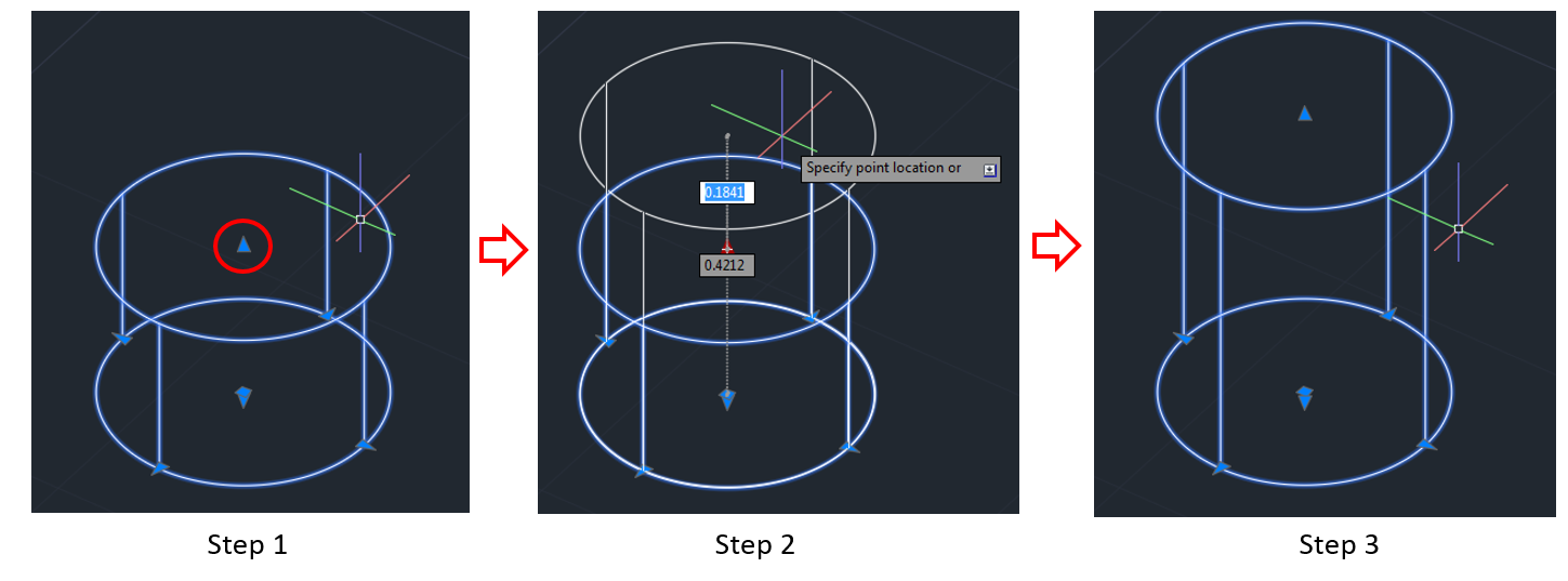
The top and bottom face center points can be used to change the height of the cylinder as follows:
- Pick one of the face center points (the blue arrow pointing outside the cylinder).
- Move the face to the new desired location. Observe that the shape of the cylinder will change dynamically as the mouse moves. You can also enter the desired value using the keyboard.
- When you arrive at the desired location, click to finish.
The following screenshot is an illustration of the previous steps:
And finally, the base point (highlighted as a square in the bottom face center point) can be used to pick and move the cylinder, and then paste it at the desired location.
There are a number of options associated with the Cylinder command. These options make provision for alternative methods in creating the Cylinders. The first set of options appears in the command bar right after you start the command:
![]()
The first three options in this set are alternative methods for creating the base circle, followed by an option to create the cylinder with an elliptical base:
- The first option is called 3P, which stands for three points. To choose this option, you can click on the option name in the command bar, or you can type 3P and then press Enter. When this option is selected, you will draw the base circle by specifying the location of three points situated on the base circle circumference:

- The second option is called 2P, which stands for two points. To choose this option, you can click on the option name in the command bar, or you can type 2P and then press Enter. When this option is selected, you will draw the base circle by specifying two points located on the diameter in the base circle, as shown in the following screenshot:

- The third option is called Ttr, which stands for Tangent Tangent Radius. This option can be selected by clicking on the option name in the command bar, or by just typing T and then pressing Enter. When you select this option, you can create the base circle to be tangent to any two other curves in the drawing, as shown in the following step-by-step example:
- Move the cursor near the first curve. The tangent icon will appear. Click to specify the first tangent curve.
- Move the cursor near the second curve. The tangent icon will appear. Click to specify the second tangent curve.
- Type the radius value and then press Enter. Alternatively, you can use the mouse to specify the radius.
The following screenshot is an illustration of the previous steps:

- The last option is called Elliptical. This option can be selected by clicking on the option name in the command bar, or by just typing E and then pressing Enter. This option allows you to draw the elliptical base instead of a circle, as shown in the following step-by-step example:
- Click to specify the location of the ellipse's first axis endpoint. You also have the option to specify the center by selecting the Center option from the command bar.
- Move and click again to specify the second point of the first axis.
- Move to specify the orientation of the ellipse and the length of the second axis, and then click to confirm.
- Specify the height of the cylinder as usual.
- The command terminates and the cylinder is created.
The following screenshot is an illustration of the previous steps:

The second set of options appear after you determine the center of the cylinder. This set contains one option called Diameter, and this allows you to enter the diameter of the cylinder instead of the radius in the default case, as shown in the following screenshot:
![]()
The third set of options appears after you draw the base. This contains two options, as shown in the following screenshot:
![]()
- The first one is called 2Point, which is an alternative method for specifying the height of the cylinder. It is exactly the same as the 2P method in the Box command (for more details on the 2P method, please refer to the Creating Boxes section).
- The second option in this set is called Axis endpoint. To select this option, you can click on the option name in the command bar, or you can type the letter A and then press Enter. The axis endpoint allows you to change the orientation of the cylinder, as shown in the following step-by-step example:
- Activate the Axis endpoint option.
- Move the mouse cursor to change the orientation of the cylinder axis.
- When you reach the desired orientation, click again.
The following screenshot is an illustration of the previous steps:

We have learned about the creation of two shapes. Now, let's take a look at the next 3D object, which is a cone.