
Chapter 30
Creating Assembly Drawings
Most of the actual tools that you might use for part drawings are the same for assembly drawings, with a few exceptions. This chapter covers these exceptions along with some special techniques that might make using assembly drawings easier or clearer.
Combining Parts and Assemblies on the Same Drawing
Every company seems to do things differently when it comes to assembly drawings. Some use the drawings for Bill of Materials (BOM) illustration, some to manufacture assembly instructions, and some to dimension assembly-based features that are applied only after the individual components are assembled.
There is nothing to prevent you from putting parts and assemblies on the same drawing or even in the same sheet. Some users place an exploded view of the assembly on the first sheet and then start detailing each part on the same sheet, using multiple sheets, so the single drawing file documents several individual parts and the assembly. This is usually the case only for simple parts. An assembly made from several complex plastic parts couldn't be done this way, because a single complex plastic part often requires multiple sheets on its own.
Dimensioning Assembly Features
One of the more difficult questions you must answer when dimensioning assembly features on an assembly drawing is what to use as your reference. Making cuts and measuring often takes place in some kind of fixture. Fixtures make excellent references in most situations. You might consider designing the fixture in some way that enables measurement from a fixed reference either on one of the parts or on the fixture itself. This would require a drawing that acts as a qualification reference to include the fixturing reference in the drawing. This is best done as a higher-level assembly rather than adding the fixture using configurations of the product-level assembly.
Measuring to reference planes in the assembly is fine for the design, but there are no reference planes in your manufacturing floor unless they are physical faces of fixtures created for the purpose of making measurements. If your measurement spans multiple parts, keep in mind that both the individual parts and the assembly have tolerances you must consider.
Assembly cuts often are used to create 3D cutaway views. SolidWorks can't create a section view where the section cut isn't perpendicular to the sheet of paper, so the workaround is to make a cut in the assembly (as a configuration) and to display the cut assembly using an isometric view. Another method is to use the 3D Rotate function to temporarily rotate the view and select something you can't see in that view. The result remains parametric.
Assigning the Document Driving the Custom Properties
When you have a drawing with multiple parts or assemblies on it, you can control which document drives the custom properties used in the title block for that sheet. If you have multiple sheets, you can have different models driving the properties on different sheets.
To use this feature, right-click the sheet in the FeatureManager or in the graphics window (but not on other items such as the format or views) to display the RMB menu shown in Figure 30.1. Make sure the gray area on the RMB menu is labeled Sheet rather than View, and select Properties from the menu. The Sheet Properties dialog box will appear, as shown in Figure 30.1.
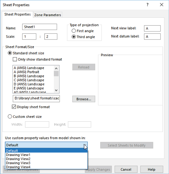
FIGURE 30.1 Assigning the driving document for a sheet
Click the drop-down list in the lower-left corner, labeled Use Custom Property Values From Model Shown In, and choose any view that's on the current sheet. This could be a single part or an assembly.
Remember also that when linking to a property, you can choose to link to properties of the current document (drawing), the model specified in the sheet properties, the component to which the annotation is attached, or the selected component. You can find these settings in the Link To Property dialog box, shown in Figure 30.2, by clicking the Link To Property icon in the Note PropertyManager.
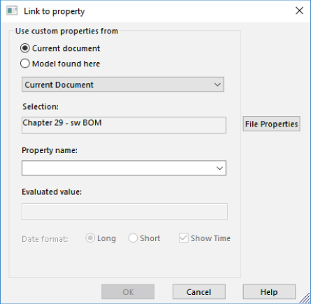
FIGURE 30.2 Linking a note to a custom property from one of various documents
Using Multi-Page Templates
Assembly drawings often become multi-page documents. To speed up your creation of these drawings, you should have multi-page templates available to use when you need them. Most of the aspects of single-page and multi-page templates are the same, such as custom property setup and formats, but adding the page gives you some options about which you need to be aware.
You can use a “page 2 format” for any page other than page one. Generally, page 2 formats are just a minimal version of a page 1 format, removing information that might be considered redundant on every page of the drawing and allowing more space for drawing content. Figure 30.3 shows page 1 and page 2 formats.
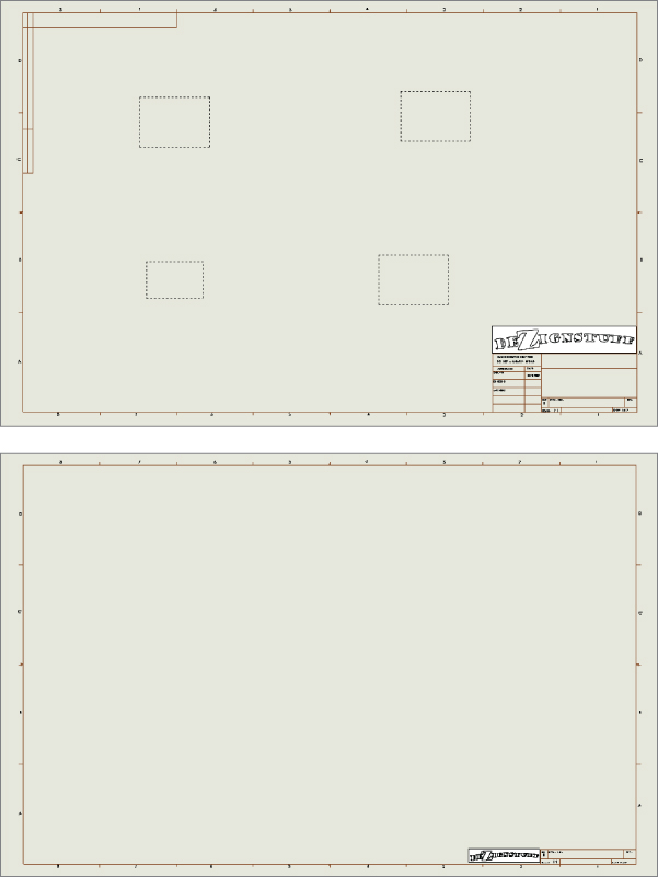
FIGURE 30.3 Using a different format for the first page and subsequent pages of a drawing
To make it easier to manage a large package of paper drawings, most multi-sheet drawings use the same size sheet for every sheet. However, every company has its own standards, conventions, customs, and needs.
To make a page 2 template from a page 1 template, follow these steps:
- Open a new drawing using the sheet format that you would like to make into a page 2 format.
- Right-click inside the sheet, but off of other items such as predefined views or the actual format, and select Edit Sheet Format from the menu.
- Edit the format to suit your needs. This might include moving, removing, or adding lines to the border, removing linked notes, or resizing or moving a logo or other items.
- Use a note linked on the drawing showing that the current page is Page X of Y. Both X (current sheet) and Y (total sheets) are available as properties you can link to the drawing from notes.
- When you have the format the way you want it, save it to a special location in your library for drawing formats. You should avoid putting customized documents in folders in the SolidWorks installation directories or in default folders created by SolidWorks. For example, you can put your format documents on the
D:drive (a physically separate drive from where the Windows operating system is installed) in a folder calledD:LibraryFormats. This ensures that installing or uninstalling SolidWorks or the operating system won't delete or overwrite your customized documents.
Using Views with Special Assembly Functions
SolidWorks has some drawing view types that have special functionality when used with assemblies. The main ones are alternate position views, exploded views (although an exploded view is not so much a function of the drawing), Broken-Out section views, and section views with alternating hatching.
Using the Alternate Position View
![]() The alternate position view is available only for views of an assembly and shows the assembly in two different positions (not from different viewpoints; this requires an assembly that moves). This is another view type that doesn't create a new view but alters an existing view. Figure 30.4 shows the PropertyManager interface for the alternate position view, a sample view that it creates, and the way it's represented in the drawing FeatureManager.
The alternate position view is available only for views of an assembly and shows the assembly in two different positions (not from different viewpoints; this requires an assembly that moves). This is another view type that doesn't create a new view but alters an existing view. Figure 30.4 shows the PropertyManager interface for the alternate position view, a sample view that it creates, and the way it's represented in the drawing FeatureManager.
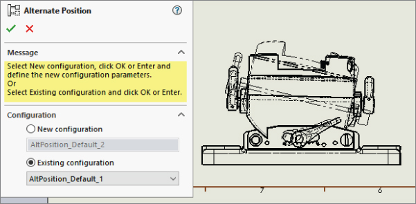
FIGURE 30.4 The alternate position view
To create an alternate position view, ensure that you have an assembly on the active drawing that can have multiple positions, and click the Alternate Position View button on the Drawings toolbar, or choose Insert ➢ Drawing View ➢ Alternate Position and then select the alternate position view.
Next, click in the drawing view to which you want to add the alternate position. The PropertyManager shown in Figure 30.4 will prompt you to select an existing configuration for the alternate position or to create a new configuration. If you choose to create a new configuration, the model window will appear, a new configuration will be created, and you will be required to reposition parts in the assembly. The alternate position is shown in a different line font on the same view and from the same orientation as the original.
To delete an alternate position view, select it in the drawing FeatureManager and press Delete.
Creating Views of an Exploded Assembly
![]() Assemblies are often depicted with the parts pulled apart in a structured way to illustrate disassembly or, more simply, the parts within the assembly. Exploded assemblies can be shown on assembly drawings using balloons with numbers corresponding to a BOM table.
Assemblies are often depicted with the parts pulled apart in a structured way to illustrate disassembly or, more simply, the parts within the assembly. Exploded assemblies can be shown on assembly drawings using balloons with numbers corresponding to a BOM table.
Here is the workflow for creating an exploded view:
- Open an assembly. Use the downloaded
rear derailleur.sldasmfor this example. - Click the ConfigurationManager tab at the top of the FeatureManager area.
- Activate the configuration you want to explode, right-click the configuration, and select New Exploded View from the menu. You are allowed to have more than one explode feature per configuration. Figure 30.5 shows the PropertyManager for the Explode command.
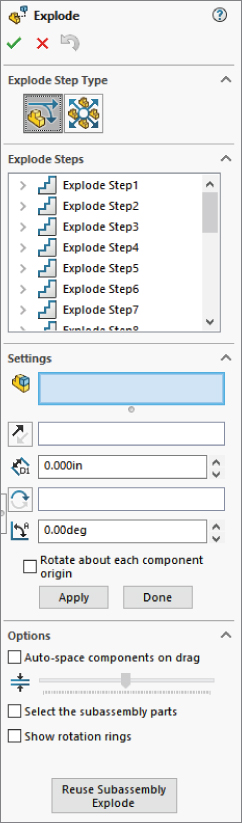
FIGURE 30.5 Starting to create an exploded view of an assembly
- Select a component to explode away from the rest of the parts. Usually, parts move axially if mated with a Concentric mate and perpendicularly away from the other parts if mated with a flat to flat coincident. Select the parts to be exploded together (in one move) in a group in the Settings selection box.
Making selections in the Settings box is not as fussy as making selections for mates or other purposes. It doesn't matter if you select a face or an edge; SolidWorks understands that you want to select the part.
- If you need to move the parts in a direction other than the assembly X, Y, or Z, use the Explode Direction box immediately below the bigger Components To Explode selection box in the Settings panel. In Figure 30.6, the Explode Direction box contains a temporary axis.
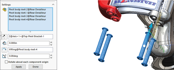
FIGURE 30.6 Selecting rivets to explode
- With the rivets selected and the direction established, drag one of the arrows on the Triad that appears in the graphics window, or type a number in the distance box in the PropertyManager. This brings up a ruler along which you can judge the explode distance.
This action produces the first explode step in the Explode Steps box in the PropertyManager. You can rename, edit, and delete the explode step.
- To make edits, select an explode step in the assembly FeatureManager. To select a step without editing it, use Ctrl+select. This enables you to change anything you used to create the step. You can use the orange arrows to change the explode distance or rotation.
Figure 30.7 shows a completed explode for the assembly.
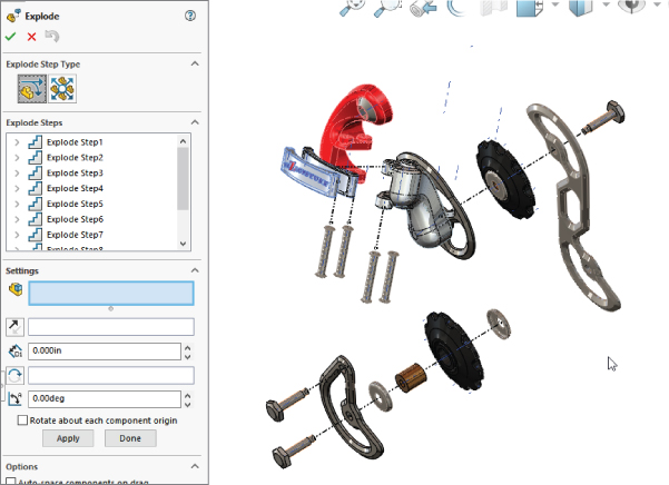
FIGURE 30.7 The completed explode for this assembly
- When you are finished with the Explode command, click the green checkmark icon to accept the results.
The completed results of an explode are displayed as an exploded view indented under the configuration from which you started the explode.
To collapse an exploded view, right-click it under the configuration and select Collapse. This will allow you to toggle back and forth between a collapsed and exploded view. Another option is Animated Explode/Collapse. This option uses the order in which the explode steps appear in the ConfigurationManager and a default speed.
ADDING EXPLODE LINES
![]() Explode lines are 3D sketch lines that show the explode path of the parts in an exploded view of an assembly. The Exploded View flyout toolbar is on the assembly toolbar by default. It includes three icons: Exploded View, Explode Line Sketch, and Insert/Edit Smart Explode Line Sketch.
Explode lines are 3D sketch lines that show the explode path of the parts in an exploded view of an assembly. The Exploded View flyout toolbar is on the assembly toolbar by default. It includes three icons: Exploded View, Explode Line Sketch, and Insert/Edit Smart Explode Line Sketch.
To use the route line as a part of the Explode Line Sketch, you simply click the features that you want to connect with an explode line, use the arrows that appear to determine which direction the sketch should connect to the part, and then click the RMB to accept the line and move on to the next. The process is shown in Figure 30.8.
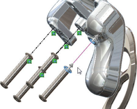
FIGURE 30.8 Drawing route lines in an exploded view
In cases where you want to move a line that the Route Line feature has created, move your cursor over the line; two small arrows will appear, as shown in Figure 30.9. They will enable you to move that line.
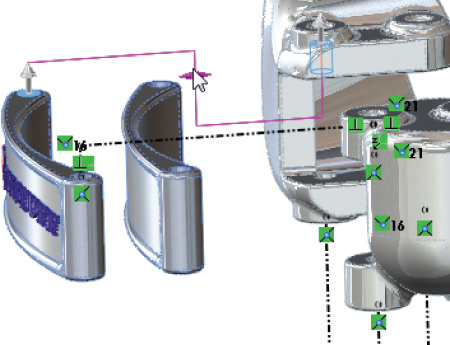
FIGURE 30.9 Moving a route line as it is created
![]() You might think that SolidWorks would be able to create these lines automatically from the data in the exploded view, and it can, to an extent, with Smart Explode Lines. To create Smart Explode Lines, right-click on the explode view in the ConfigurationManager and select Smart Explode Lines. This creates what is shown in Figure 30.10.
You might think that SolidWorks would be able to create these lines automatically from the data in the exploded view, and it can, to an extent, with Smart Explode Lines. To create Smart Explode Lines, right-click on the explode view in the ConfigurationManager and select Smart Explode Lines. This creates what is shown in Figure 30.10.
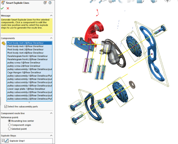
FIGURE 30.10 Adding Smart Explode Lines to an exploded assembly view
SHOWING EXPLODED VIEW
The best view orientation to use for an exploded view on a drawing is usually not one of the standard views. To create a custom view orientation, use the mouse to orient the view in the way that you want the assembly displayed on the drawing, and then open the assembly and press the spacebar to open the View Orientation box. Click the New View button and name the new view orientation.
Now you can place the new view on the drawing. To show the view in the exploded state, right-click inside the view (but off any part geometry), select Properties, and choose the Show In Exploded State option, as shown in Figure 30.11.
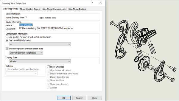
FIGURE 30.11 Showing the exploded state on the drawing
Creating Section Views
Section views are common enough in part drawings, but when you section an assembly, you must consider other things, such as not cutting fasteners and shafts. You can create assembly sections with the same options that you use for part sections, partial sections, aligned sections, and broken-out sections. Assembly sections can even be created in the model and dragged onto the drawing sheet from the View palette.
EXCLUDING PARTS FROM SECTION VIEWS
When creating a section view, you can exclude parts from being sectioned. Figure 30.12 shows the Section Scope tab of the Section View dialog box, which enables you to do this. You can also access this dialog box when editing a section view through the Section View PropertyManager by clicking the More Properties button at the bottom and then choosing the Section Scope tab.
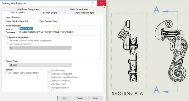
FIGURE 30.12 Excluding bolts and pins from the section view of this assembly
ISOMETRIC SECTION
To easily create an isometric section view, first create a regular section view, then right-click on it, select Isometric Section View from the menu, and place the new view. See Figure 30.13.
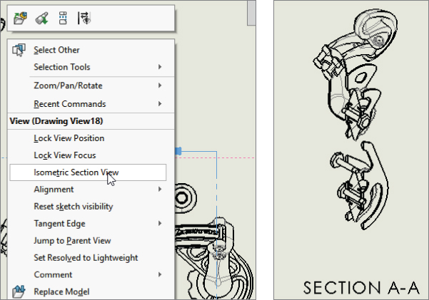
FIGURE 30.13 Isometric section
To undo this, or to set the view back to a regular section view, right-click in the view and select Remove Isometric View.
ALIGNING THE VIEW
In this case, the section line is slightly angled, and you would like to have the section view laid out straight. To orient a view in a particular way, select an edge that you want to be horizontal or vertical (assuming there is one; if not, you may have to use a sketch line or axis), and using the menus, select Tools ➢ Align Drawing View and then select either Horizontal Edge or Vertical Edge.
Remember that you can always rotate the view on the sheet with the Rotate button on the Heads-Up View toolbar on the drawing, or the 3D Rotate function. This displays a dialog box where you can type in a specific value.
ADJUSTING THE HATCHING
The default hatching may not be the right size for the parts you build. If you need to adjust the hatching—the size, the pattern, or the angle—just click the sectioned part, and the Area Hatch/Fill PropertyManager will appear. Figure 30.14 shows the PropertyManager and a hatched section view.
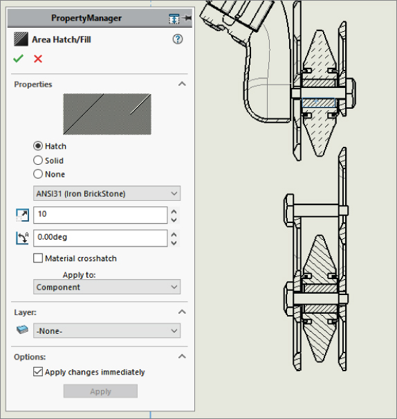
FIGURE 30.14 Using the Area Hatch/Fill PropertyManager
You can change hatching for each part (component), body, the entire view, or just the selected enclosed region. Be sure to make the right selection in the Apply To drop-down menu before you exit the Area Hatch PropertyManager.
Hatching is assigned with the material found at the top of the SolidWorks FeatureManager for each part. Each material has its own crosshatch. If a material is not formally assigned to a part, the default hatching is set in Tools ➢ Options ➢ Document Properties ➢ Material Properties settings. The default is ANSI31 (Iron BrickStone). The default can be set in part templates. This is also where the default density is established, as shown in Figure 30.15.
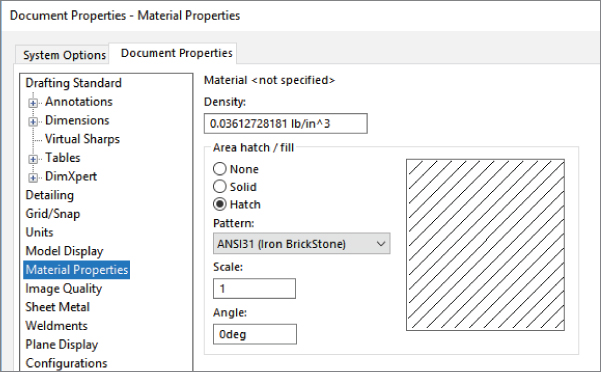
FIGURE 30.15 Changing the defaults for density and crosshatch
Broken-Out Section View
![]() The Broken-Out section view is a view type that alters an existing view rather than creating a new view. It also requires a closed-loop sketch to define the section. The Broken-Out section view is very useful when a set of parts is inside a housing and you want to show the inside parts without hiding the housing. Of course, you can also use a Broken-Out section view on single parts with internal detail.
The Broken-Out section view is a view type that alters an existing view rather than creating a new view. It also requires a closed-loop sketch to define the section. The Broken-Out section view is very useful when a set of parts is inside a housing and you want to show the inside parts without hiding the housing. Of course, you can also use a Broken-Out section view on single parts with internal detail.
A Broken-Out section view acts like a cut that's created from the drawing view. Any faces created by the cut are hatched. Figure 30.16 shows a simple assembly view using a Broken-Out section view. On the left is the view with the driving sketch (in this case, a closed-loop spline), and on the right is the finished view. You cannot create a Broken-Out section view using existing detail, section, or alternate position views.
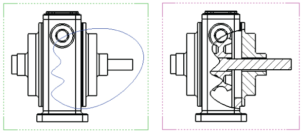
FIGURE 30.16 A Broken-Out section view
A Broken-Out section view requires you to specify a depth for the cut. You can use an edge selected from a different view or a distance to specify the depth. In the case of the broken-out section, the depth is into the screen; with the regular section, the depth is measured as a distance perpendicular to the section line.
DRAWING THE CLOSED LOOP
A Broken-Out section view is initiated from an existing view either with or without a pre-drawn closed loop. If the loop is pre-drawn, then you must select it before clicking the Broken-Out Section button on the Drawings toolbar or accessing the command by choosing Insert ➢ Drawing View ➢ Broken-Out Section.
A Broken-Out section view is traditionally created with a freehand sort of boundary, even when drawn manually.
Two basic workflows exist for creating a Broken-Out section:
The preferred method is to use a spline loop, as indicated here:
- Click the Broken-Out Section button.
- SolidWorks will automatically present you with the Spline sketch tool.
- Sketch a closed-loop spline.
- Select any excluded components (Section Scope).
- Select the depth of cut.
The pre-selected loop method is used for nonspline cutting loops, as indicated here:
- Sketch a loop using either spline or nonspline sketch elements
- Select the loop using Ctrl+select, box/lasso selection, or an RMB method such as Select Chain.
- Click the Broken-Out Section button.
- Select any excluded components (Section Scope).
- Select the depth of the cut.
SELECTING THE DEPTH
After you make the Section Scope selections, the next step is to set the depth of the cut. You can do this in several ways. A Broken-Out section view is usually cut to the center of a hole if a circular edge is selected. If you know the depth of the cut you want to make, you can enter it as a distance value. Of course, that raises the question, “Distance from what?” The answer seems to be “from the geometry in the view that is closest to the user.”
In situations when you want to cut to the center of a particular feature or up to an edge, it's far easier to simply select the geometry from a drawing view. It could be the same view as the Broken-Out section or a different view of the same document (part or assembly). For example, Figure 30.17 shows the PropertyManager interface where the depth of the cut is set. In this example, the edge of the shaft in the view to the right has been selected. This tells SolidWorks that the cut should go to the center of the shaft. Another possibility is to show the temporary axes, as shown in Figure 30.17, and to select an axis through the center of the shaft.
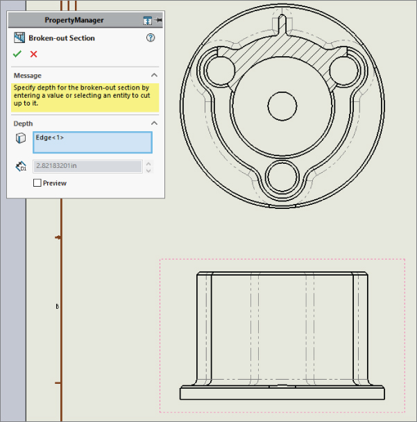
FIGURE 30.17 Setting the depth of the Broken-Out section view
EDITING THE VIEW
At this point, the view is finished. Now you may choose to edit the view in some way, such as by changing the sketch, the depth, the section scope, and so on. Figure 30.18 shows how the Broken-Out section view is positioned in the Drawing FeatureManager. It's listed as a modification to an existing drawing view. The Broken-Out Section RMB menu is also shown. Selecting Edit Definition displays the PropertyManager (refer to Figure 30.17). Selecting Edit Sketch enables you to change the section spline shape. Selecting Properties displays the dialog box shown in Figure 30.18. This contains options for the underlying original view as well as the Broken-Out Section modification to the original view. Only the Section Scope tab is added by the Broken-Out section view. The rest of the options are for normal view properties.
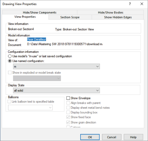
FIGURE 30.18 Editing the Broken-Out section view's properties
Using Color in Assembly Drawing Views
You can apply the same color to the wireframe display on the drawing that you have applied to the individual parts in the Assembly window. Colors on drawings help distinguish one part from another in assemblies, where the alternative is to look at a screenful of black lines.
On the other hand, sometimes light colors that show up well when the part is shaded on the screen don't look good when used in a wireframe line width on a white sheet. Also, with the use of part “appearances” where some people are using more realistic material displays for parts, part colors can be a range of gray to reflect surfaces such as aluminum or steel. Still, if you want to set your parts up with more abstract contrasting colors, it helps you to distinguish one part from another in the assembly model and on the drawing. Appearances, even realistic or reflective appearances, can have colors assigned to them, so you get a shiny, red steel part. The realism is far less important than the ability to tell one part from another, so the abstraction of colors that don't look realistic at all is often very helpful.
To make assembly drawings use part color, use the setting indicated by the cursor in Figure 30.19, Tools ➢ Options ➢ Document Properties ➢ Detailing ➢ Use Model Color For HLR/HLV In Drawings. You need to specify this document property setting in the drawing. (HLR stands for hidden lines removed, while HLV stands for hidden lines visible.)
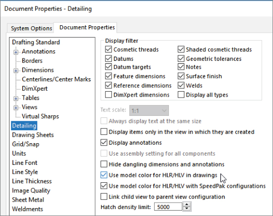
FIGURE 30.19 The Use Model Color For HLR/HLV In Drawings option
This is worth repeating: Even though this setting exists in both the assembly and the drawing, and even though there is a setting in parts that says to use the same color for shaded and wireframe, the only setting that matters in terms of getting color onto the drawing is Use Model Color Setting in the Drawing Document Properties.
Setting Up Drawings of Large Assemblies
You can use several tactics to try to minimize the overhead of working with large data sets in SolidWorks drawings. You have several options when working to improve the performance of large assembly drawings. Some of these options should be employed at the level of the assembly, and some you will use only in the drawing.
Using Detached Drawings
![]() Detached drawings don't have the 3D document files loaded in memory; they just let you work with the geometry as is in the drawing. They can be beneficial in two situations: first, to speed up large assembly drawings, and second, when you have the drawing but don't have the part and assembly files. You must set up a detached drawing before deciding to open the drawing without the parts. Detached drawings use the symbol at the top of this paragraph to denote their special status both in the Windows Explorer/Open dialog and in the drawing FeatureManager.
Detached drawings don't have the 3D document files loaded in memory; they just let you work with the geometry as is in the drawing. They can be beneficial in two situations: first, to speed up large assembly drawings, and second, when you have the drawing but don't have the part and assembly files. You must set up a detached drawing before deciding to open the drawing without the parts. Detached drawings use the symbol at the top of this paragraph to denote their special status both in the Windows Explorer/Open dialog and in the drawing FeatureManager.
To create a detached drawing, choose File ➢ Save As, and from the Save As Type drop-down list (shown in Figure 30.20), select Detached Drawing.
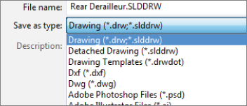
FIGURE 30.20 Saving a drawing as a detached drawing
You cannot perform some drawing operations with detached drawings, including these:
- Crop views
- Break views
- Section views
- Alternate position or relative views
- Insert model items
Detached drawings also cannot be lightweight.
Just like other operations in SolidWorks drawings, when the view needs to be updated, the view becomes hatched.
When you need to load the model to update changes or do one of the operations that require the part data to be present, right-click inside a view and select Load Model from the menu. When SolidWorks determines that you need to load the model, the software may prompt you to do this. Another option is to load the model from the File Open dialog.
You can only add certain types of views of parts—not the assembly (aux, projected, section, broken-out section), annotations, and reference dimensions to a detached drawing. So, there's a certain amount of work you can actually do with detached drawings. To remove these limitations, you can load the model.
If you save a drawing as detached, load the model, and then save the drawing and close it, the next time you open it, it will be detached. In other words, after you save a drawing as detached, it remains detached until you save it as a regular drawing. To do this, just choose File ➢ Save As, and in the File of Type drop-down list, select Drawing.
Further, be aware that Ctrl+Q (forced rebuild) will load the model without warning, while Ctrl+B (rebuild) at least gives you a warning. Also, if a drawing is linked to multiple parts, loading one will load all.
Working with Lightweight Drawings
Lightweight drawings have some similarities to lightweight assemblies. With lightweight drawings, SolidWorks loads only as much model data as it needs. If SolidWorks needs more data, it loads it. This helps assemblies and drawings to open more quickly, but some functions may be slower.
Using lightweight settings in the drawing works just like using lightweight settings in the assembly. Right-click in a view (either in the graphics window or the FeatureManager), and select Set Resolved To Lightweight, as shown in Figure 30.21. Doing this for one view sets all views to Lightweight (it is the assembly behind the view that is lightweight, not the view itself). You can resolve the assembly by choosing Set Lightweight To Resolved from the RMB menu.
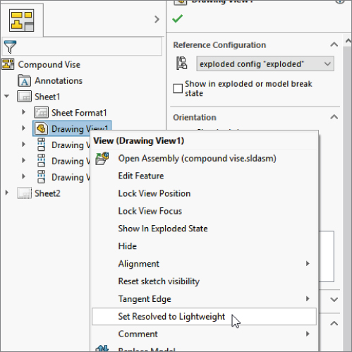
FIGURE 30.21 Using lightweight settings with assembly drawings
Using SpeedPak with Drawings
![]() SpeedPak is a derived assembly configuration type that uses selected geometry to simplify the display and amount of data SolidWorks needs to load a complex assembly, with the goal of speeding up loading and work in general. To create a SpeedPak, right-click on an existing configuration in an assembly and select Add SpeedPak, and then use selection techniques to select faces, bodies, reference geometry, sketches, and curves to be displayed as part of the SpeedPak. Your selections will be displayed in assemblies and drawings in place of the full configuration geometry.
SpeedPak is a derived assembly configuration type that uses selected geometry to simplify the display and amount of data SolidWorks needs to load a complex assembly, with the goal of speeding up loading and work in general. To create a SpeedPak, right-click on an existing configuration in an assembly and select Add SpeedPak, and then use selection techniques to select faces, bodies, reference geometry, sketches, and curves to be displayed as part of the SpeedPak. Your selections will be displayed in assemblies and drawings in place of the full configuration geometry.
The Quick Include functionality will automatically include geometry based on your selected position on the More To Less slider. It selects more or less detail for the views you specify in the SpeedPak PropertyManager interface, shown in Figure 30.22.
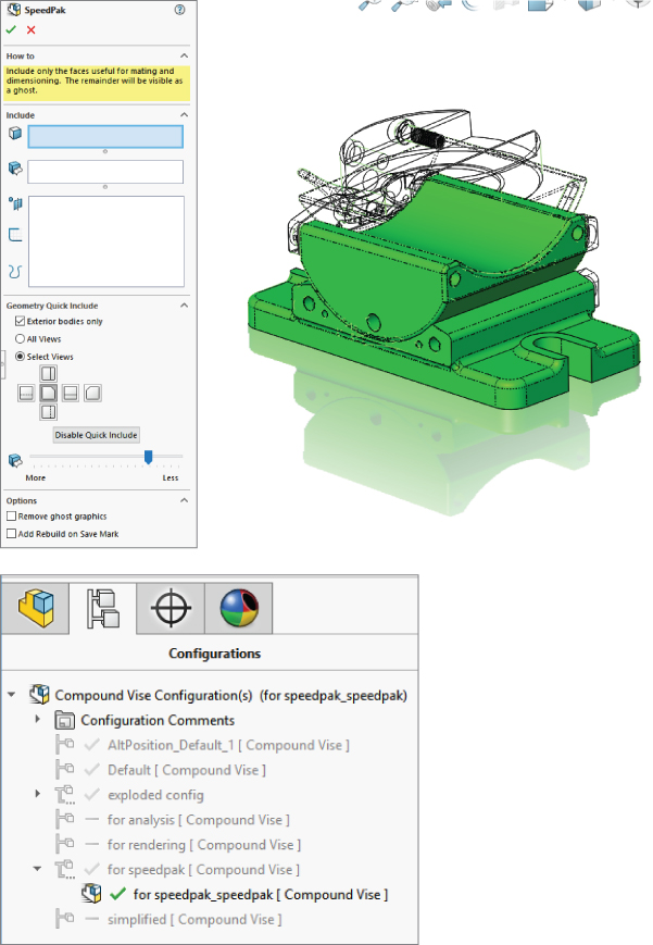
FIGURE 30.22 The SpeedPak PropertyManager
Once created, the SpeedPak is listed in the assembly ConfigurationManager under the configuration, like a derived configuration, but with a special SpeedPak icon, shown in Figure 30.22.
Ghost graphics are anything that is not selected in the Included boxes. Ghost graphics are visible, but not selectable. If you select the Remove Ghost Graphics option in the SpeedPak PropertyManager, only the items you have included will be visible when the SpeedPak is in use (either in the assembly or the drawing). Figure 30.23 shows the model with and without the ghost graphics.
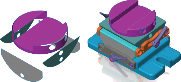
FIGURE 30.23 Model with and without ghost graphics
If you want to use a SpeedPak in a drawing, the SpeedPak must include edges to which you want to dimension. Anything that's part of the ghost data will be shown in gray by default, but this is sometimes changed to another convenient color such as black. To use an existing SpeedPak for an assembly, right-click a view and select Properties. In the Configuration information, use the named configuration option to select the derived configuration of the SpeedPak.
Using Draft Quality Views
![]() Draft Quality views are another way to speed up large assembly drawings. Figure 30.24 shows the difference between a Draft Quality view on the left and a High Quality view on the right. Each view starts as a Draft Quality view; however, when you change from Draft Quality to High Quality, the setting will no longer be available. You can find the Draft Quality and High Quality view settings in the view PropertyManager (just select a view, and the PropertyManager will appear on the left) in the Display Style panel. This will enable you to change from Wireframe to Shaded display modes. If the High Quality and Draft Quality toggles are not in the PropertyManager panel, then the view is already in High Quality mode. After you switch a view to High Quality, you cannot switch it back to Draft Quality.
Draft Quality views are another way to speed up large assembly drawings. Figure 30.24 shows the difference between a Draft Quality view on the left and a High Quality view on the right. Each view starts as a Draft Quality view; however, when you change from Draft Quality to High Quality, the setting will no longer be available. You can find the Draft Quality and High Quality view settings in the view PropertyManager (just select a view, and the PropertyManager will appear on the left) in the Display Style panel. This will enable you to change from Wireframe to Shaded display modes. If the High Quality and Draft Quality toggles are not in the PropertyManager panel, then the view is already in High Quality mode. After you switch a view to High Quality, you cannot switch it back to Draft Quality.
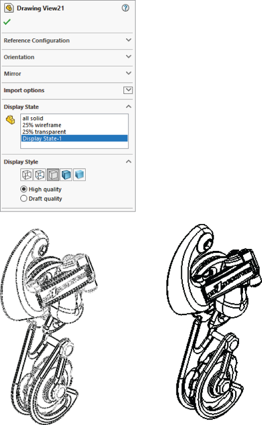
FIGURE 30.24 Comparing High Quality and Draft Quality views
You can change the defaults for this setting in the System Options at Tools ➢ Options ➢ Drawings ➢ Display Style ➢ Display Quality For New Views. As you might imagine, this is not a template setting; it's only a system option. To return to Draft Quality, first make sure your system is set up to create Draft Quality views, then simply switch from HLR or HLV to Shaded and back.
Keep in mind that it's easy to confuse the Cosmetic Thread Display with the Display Style. They both toggle between High Quality and Draft Quality, and when you are just looking for those features, you may settle on the first one you see with this label.
High Quality views store the detailed information (used in zoom operations) in the drawing, while Low Quality views have to go back to the model to get that data. Thus, while High Quality views take more memory, they are faster to zoom in and out. But you have to make sure your hardware can handle the extra memory requirements.
Tutorial: Creating a Simple Assembly Drawing
This tutorial guides you through creating a simple assembly drawing:
- Create a new drawing from the New dialog box. Select
Inch B Bible Template (no Views).drwdot; as the filename indicates, this template document has no predefined views. If you select a default SolidWorks template, you need to verify that the template uses third angle rather than first angle projection. An easy way to do this is to switch the drafting standard from ISO to ANSI in Tools ➢ Options ➢ Document Properties ➢ Drafting Standard. If the automatic Model View interface appears in the PropertyManager, click the red X icon to cancel out of it. - Expand the Task pane and activate the View palette (the tab that looks like a drawing icon). Click the ellipsis button (…) and browse for the assembly named
SF casting assembly.sldasm. The View palette is shown in Figure 30.25.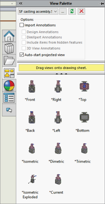
FIGURE 30.25 The View palette
- Drag the back view onto the drawing. Notice that when you use this technique, the views do not resize automatically, regardless of the setting at Tools ➢ Options ➢ Drawings ➢ Automatically Scale New Drawing Views.
- Delete any view you have created using this method. Open Windows Explorer, browse to the assembly, and drag it into the drawing. The views that you create using this method are equivalent to the Standard 3 View tool. This time, the views automatically size.
- Select the front view and change it to the back view. Use the Orientation panel of the View PropertyManager. Notice that the rest of the views change to reflect the new parent view. You will get a warning about this change.
- Zoom in on the back view. Change the view to show Tangent Edges With Font through View ➢ Display. You can also make this change from the view RMB menu, the Tangent Edge selection.
- Click the Alternate Position View toolbar button. Type a name in the PropertyManager for a new configuration and click the green checkmark icon. SolidWorks will open the Assembly Model window.
- Rotate the handle 90 degrees and click the green checkmark icon. SolidWorks will return to the drawing and show the new position in a dashed font, as shown in Figure 30.26.
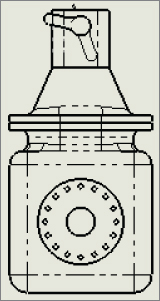
FIGURE 30.26 Creating an alternate position view
- Place an isometric view on the drawing. Change the Display mode to make it a shaded view.
- Right-click inside the view (but away from the parts) and select Properties. The Drawing View Properties dialog box will appear, displaying the View Properties tab, as shown in Figure 30.27. Make sure the view is set to use the Default configuration, with the Default display state, and select the Show In Exploded Or Model Break State option.
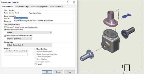
FIGURE 30.27 The Drawing View Properties dialog box
The Bottom Line
Working with assembly drawings requires many of the same skills as working with regular drawings, but with much less dimensioning, and much more pictorial and visualization capability. Sometimes, you must use the unique tools for assembly drawings to get the job done.
- Master It Create an exploded view of one of the assemblies provided with the download materials for this chapter or one of your own. Draw in the explode lines.
- Master It Use a template with a second page to create a new drawing. I suggest the template called
Mastering 2pg B size.Create a drawing of the assembly for which you created an exploded view. The first sheet should be automatically populated with three standard views and an isometric.
Show the isometric view of the assembly in its exploded state and apply balloons to all the parts.
Place a Bill of Materials table on the drawing that shows item numbers for each balloon.
- Master It Starting with the drawing from the last practice exercise, switch to the second sheet. Click on the Standard 3 View icon on the View Layout tab. Select one of the parts from the assembly. If you have not opened any parts individually, you'll have to browse for it.
Place the views on the drawing and add an isometric view.
Put some custom properties in the part and make sure that the title block on the second page format picks up some of the part information.