
Chapter 9
Patterning and Mirroring
Patterning and mirroring in SolidWorks are great tools to help you improve your efficiency. SolidWorks software provides many powerful pattern types that also help you accomplish design tasks. In addition to the different types of patterns, some options enable functionality that you may not have considered.
Patterning in a Sketch
You can use both pattern and mirror functions in Sketch mode, although sketch patterns are not a preferred choice because 3D patterning is generally more efficient. The distinction between patterning and mirroring in Sketch mode is important when it comes to sketch performance.
You might hear a lot of conflicting information about which features are better to use in different situations. Users coming from a 2D background often use a function such as sketch patterning because it's familiar, without questioning whether a better approach is available, and often without having a way of measuring how it performs. When in doubt, you can perform a test to determine which features work best for a given situation.
To compare the performances of various types of patterns, I made a series of 20 × 20 patterns using circles, squares, and hexagons. The patterns are both sketch patterns and feature patterns, and I created them with both Verification On Rebuild and Geometry Pattern turned on and off. Verification On Rebuild is an error-checking setting that you can access through Tools ➢ Options ➢ Performance. Geometry Pattern is a setting that is applicable only to feature patterns, and it disables the intelligence in patterned features.
Table 9.1 shows the rebuild times (in seconds) of solid geometry created from various types of patterns as measured by Performance Evaluation. (It is found at Tools ➢ Evaluate ➢ Performance Evaluation; this was formerly called Feature Statistics.) Sketch patterns are far slower than feature patterns, by a factor of about 10. The biggest speed reduction occurs when you use sketch patterns in conjunction with the Verification On Rebuild setting, especially as the number of sketch entities being patterned increases.
TABLE 9.1: Pattern Rebuild Times in Seconds
| PATTERN TYPE | DEFAULT | GEOMETRY PATTERN | VERIFICATION ON REBUILD |
| 20 × 20 sketch circle | .87 | n/a | 5.52 |
| 20 × 20 sketch square | 4.5 | n/a | 60 |
| 20 × 20 sketch hex | 9.6 | n/a | 126 |
| 20 × 20 feature circle | 0.06 | 0.53 | 0.08 |
| 20 × 20 feature square | 0.23 | 0.53 | 0.23 |
| 20 × 20 feature hex | 0.36 | 0.55 | 0.36 |
Generally, the number of faces and sketch relations being patterned has a significant effect on the speed of the pattern. The sketch pattern times are taken for the entire finished model, including the sketch pattern and a single Extrude feature, using the sketch with the pattern to do an extruded cut. The sample parts are in the download materials for this chapter for reference. Look for the filenames beginning with Reference1 through Reference7.
The most shocking data here is the difference between a sketch pattern of a hex when a patterned sketch cuts into a flat plate compared to a feature pattern of a single extruded hex with each using the Verification on Rebuild option—0.36 seconds compared to 126 seconds.
Always keep this general information about sketch patterns in mind:
- Sketch patterns are bad for rebuild speed.
- The more faces created by any pattern, the longer it takes to rebuild.
- The more sketch relations a sketch pattern has, the longer it takes to rebuild.
- Geometry Pattern does not improve rebuild speed unless a special end condition like Up To Surface has been used.
- Verification On Rebuild dramatically increases rebuild time with the number of faces but is far less affected by feature patterns than extruded sketch patterns.
Figure 9.1 shows one of the parts used for this simple test.

FIGURE 9.1 A pattern part used for the test
One interesting finding of this test was that if a patterned extruded feature creates a situation where the end faces of the extruded features have to merge into a single face, the feature could take 10 times the amount of time to rebuild as a pattern with unmerged end faces. This was an inadvertent discovery. I'm sure you will make your own discoveries if you investigate rebuild speeds for end conditions for cuts such as Through All, Up To Face, Up To Next, and so on, as well as the difference between cuts and boss features. Further, using Instant 3D can be an impediment when you're editing very large sketches simply due to the effects of the preview.
You should also note that the situation this simple test covers is very limited in scope. Because the plate is a constant thickness, the Geometry Pattern option actually works, which it wouldn't if the plate varied in thickness (with the through holes). It also tests only the Through All end condition, and the Geometry Pattern is best used to simply disable intelligent end conditions. I believe that many people use it as a random toggle trying to get patterns to work that SolidWorks would otherwise not allow to work.
I discuss the Geometry Pattern option in more detail later in this chapter. I wanted to start the chapter with a discussion that called attention to the common misperception that sketch patterns are somehow better than feature patterns.
Debunking More Sketch Myths
People often say that it is best practice to define your sketches fully. I completely agree with this statement. However, I have heard people say that fully defined sketches solve faster, with the rationale being that SolidWorks must figure out how to solve the under-defined sketch, but the fully defined sketch is already spelled out. Let's find out.
In this example, I created a sketch pattern of 4 × 4 rectangles and used the Fully Define Sketch tool to add dimensions. Then I copied and pasted the sketch and removed all the dimensions and relations. Figure 9.2 shows the Feature Statistic results.

FIGURE 9.2 Comparing the rebuild times of a fully defined sketch to a completely undefined sketch
Fully defined sketches are best practice, but it is not due to rebuild speed. Sketch relations are costly from a rebuild-time point of view. Patterning sketch relations are even more costly. The rebuild time does not even come close to the time that it takes the Fully Define Sketch tool to create all the dimensions and relations in the first place. This combination of geometry, software, and hardware took about 30 seconds of CPU time to add the relations and dimensions.
For most models that have fewer than 50 features, you may never notice this rebuild time, and the price you pay is certainly worth the peace of mind you get from having the stability of a fully defined sketch. For large models where you have hundreds of features, or features that use lots of very busy sketches, you should pay attention to how much information you put into the sketch and try to limit sketch patterns and even elements such as sketch fillets, using feature fillets instead where possible.
Patterning a Sketch
Sketch patterns are an available tool—they are valid, and in a few cases, they are truly necessary. It is best to preselect the sketch entities that you want to pattern before using the Sketch Pattern tool. If you do not preselect, then after the PropertyManager is open, you can only select entities to pattern one by one, because the window select is not available for this function. The RMB selection options, such as Select Chain, are also not available in this interface, reinforcing the need to treat sketch patterns as a preselection feature.
USING THE LINEAR SKETCH PATTERN
![]() The Linear Pattern PropertyManager is shown in Figure 9.3.
The Linear Pattern PropertyManager is shown in Figure 9.3.

FIGURE 9.3 The Linear Pattern PropertyManager
Unlike other PropertyManagers, the selected entities for the sketch pattern functions are found at the bottom of the PropertyManager instead of at the top. This is a little confusing. Sketch tool PropertyManagers, such as Convert Entities and Mirror, place the selection box at the top.
The Direction 1 panel works predictably by establishing the direction and spacing and then the number. The Angle setting enables you to specify a direction that does not rely on anything outside of the sketch.
The Direction 2 panel works a little differently. You must first specify how many instances you want, and then the other information will become available. The spacing is grayed out until you tell it you want more than one instance in Direction 2.
USING THE CIRCULAR SKETCH PATTERN
![]() The Circular Sketch Pattern option defaults to the sketch origin as the center of the pattern. You can move and position this point using the numbers in the PropertyManager, but you cannot dimension it until after the pattern is created. Again, this is another feature where you need to preselect because window selection is not available (patterned sketch entities must be selected one by one to go into the Entities to Pattern panel). Figure 9.4 shows the Circular Pattern PropertyManager.
The Circular Sketch Pattern option defaults to the sketch origin as the center of the pattern. You can move and position this point using the numbers in the PropertyManager, but you cannot dimension it until after the pattern is created. Again, this is another feature where you need to preselect because window selection is not available (patterned sketch entities must be selected one by one to go into the Entities to Pattern panel). Figure 9.4 shows the Circular Pattern PropertyManager.

FIGURE 9.4 The Circular Pattern PropertyManager
Mirroring in a Sketch
Mirroring in a sketch is a completely different matter from patterning in a sketch. It offers superior performance, and the interface is better developed. Mirrored entities in a sketch are instrumental parts of establishing design intent.
Two methods of mirroring items in a sketch are discussed here, along with a method to make entities work as if they have been mirrored when in fact they were manually drawn.
Using Mirror Entities
![]() You can use the Mirror Entities tool in two ways: with the interface or without the interface.
You can use the Mirror Entities tool in two ways: with the interface or without the interface.
Figure 9.5 shows the Mirror Entities PropertyManager.

FIGURE 9.5 Selecting items in the Mirror Entities PropertyManager
If you preselect the entities to be mirrored along with a single centerline and then click the Mirror Entities icon, you will never see the PropertyManager interface, and the regular sketch entities will be mirrored about the single centerline.
If you prefer to use the interface, just click the Mirror icon first and then select entities. If you use this method, you can mirror centerlines as well as regular lines, and you can select a regular line, an edge, or a plane in the Mirror About box. Also, you can turn off the Copy option to remove the original entities when creating the mirror. Using the interface allows you much more flexibility; avoiding the interface has some special requirements, but it's much faster.
Using Dynamic Mirror
![]() As the name suggests, Dynamic Mirror mirrors sketch entities as they are created. You can activate it by selecting a centerline and clicking the Dynamic Mirror button on the Sketch toolbar. Dynamic Mirror is not on the toolbar by default; you need to choose Tools ➢ Customize ➢ Commands to add it to the toolbar. You can also access Dynamic Mirror by choosing Tools ➢ Sketch Tools ➢ Dynamic Mirror from the menu.
As the name suggests, Dynamic Mirror mirrors sketch entities as they are created. You can activate it by selecting a centerline and clicking the Dynamic Mirror button on the Sketch toolbar. Dynamic Mirror is not on the toolbar by default; you need to choose Tools ➢ Customize ➢ Commands to add it to the toolbar. You can also access Dynamic Mirror by choosing Tools ➢ Sketch Tools ➢ Dynamic Mirror from the menu.
When you activate this function, there is no PropertyManager interface. The centerline displays with hatch marks on the ends and remains active until you turn off or exit the sketch. Figure 9.6 shows the centerline with hatch marks.

FIGURE 9.6 The Dynamic Mirror centerline with hatch marks
Using Symmetry Sketch Relation
![]() In some editing situations, you may not want to create new geometry, but will use existing entities with new relations driving them. To create the Symmetry sketch relation, you must have two similar items (such as lines or endpoints) and a centerline selected.
In some editing situations, you may not want to create new geometry, but will use existing entities with new relations driving them. To create the Symmetry sketch relation, you must have two similar items (such as lines or endpoints) and a centerline selected.
To add the symmetry relation after you have made the proper selection, use the pop-up toolbar interface or the Add Relation toolbar button. These two options are shown in Figure 9.7.

FIGURE 9.7 Two ways to add a symmetric sketch constraint
You can find more information on manipulating sketch relations in Chapter 3, “Working with Sketches and Reference Geometry.”
Using Mirroring in 3D Sketches
Chapter 6, “Getting More from Your Sketches,” deals with 3D sketches in more detail, but I discuss the mirror functionality here to connect it with the rest of the mirroring and patterning topics. You can mirror sketch entities in 3D sketches, when sketching in 3D space or on 2D planes. Mirroring in 3D space requires a plane to mirror about; then you can use the regular Mirror Entities tool that you use in 2D sketches.
Sketch patterns are unavailable in the 3D sketch, but you can use the Move, Rotate, and Copy sketch tools on planes in 3D sketches.
Working with 3D Patterns
Patterning 3D geometry—whether components, bodies, features, or faces—is extremely powerful. It saves design time, as well as compute time, when used correctly. Selecting the right type of entities to serve as the seed for the pattern can determine your success with this function.
One of the basic functions in patterns is determining the original instance (seed) from the patterned instances. These are determined by color when you select the pattern feature in the FeatureManager using the Selected Item 1 and 2 determined by the settings at Tools ➢ Options ➢ Colors. This coloring does not follow the same scheme that you see when editing or creating the feature, but at those times the seed should be obvious, as patterned instances are not shown shaded.
To be able to visualize the seed without selecting the feature, some users manually change the color of the seed.
Exploring the Geometry Pattern Option
The SolidWorks Help file says that the Geometry Pattern option in feature patterns results in a faster pattern because it does not pattern the parametric relations. This claim is valid only when there is an end condition on the patterned feature such that the feature will actually pattern the end condition's parametric behavior. The part shown in Figure 9.8 falls into this category. After you turn on the Geometry Pattern option, the improved rebuild time goes from 0.30 to 0.11 seconds. Although a 60-percent reduction is significant, the most compelling argument for the use of the Geometry Pattern has nothing to do with rebuild time. It is to avoid the effect of patterning the start- and end-condition parametrics. It ignores all settings in the feature definition. In effect, Geometry Pattern has much of the same effect as patterning faces, but with some differences.

FIGURE 9.8 A Geometry Pattern test
In fact, the Geometry Pattern option is intended to pattern existing geometry without the parametric intelligence. Geometry Pattern was not designed to improve rebuild speed.
Under some conditions, Geometry Pattern does not work. One example is any time a patterned face merges with a face that cannot be patterned. Figure 9.9 shows two patterns, one that can use Geometry Pattern and one that cannot.

FIGURE 9.9 Merged faces
The pattern of the rectangular bosses cannot use Geometry Pattern because the face that is merged is not merged in all pattern instances. The pattern of truncated cylinders shown on the same part as the pattern of rectangular bosses can use Geometry Pattern because the flat face is merged in every pattern instance. The circular pattern in the image to the right in Figure 9.9 also allows Geometry Pattern for the same reason.
In some situations, SolidWorks error messages may send you in a loop. As shown in Figure 9.10, one message may tell you that the pattern cannot be created with the Geometry Pattern turned on, so you should try to turn it off.

FIGURE 9.10 Geometry Pattern error message
When you do that, you may get another message that says the pattern will not work and that you should try to use the Geometry Pattern setting. In cases like this, you may try to use a different end condition for the feature that you want to pattern or change the selection of features patterned along with the feature, such as fillets. You may also try to pattern bodies or even faces rather than features. These last two options are covered in the following sections.
Patterning Bodies
I cover multibodies in depth in Chapter 31, “Modeling Multibodies,” but I will briefly discuss the topic here. No discussion of patterning is complete without a discussion of bodies.
SolidWorks parts can contain multiple solid or surface bodies. A solid body is a solid that comprises a single contiguous volume. A surface body is different—think of it as a sheet knitted together from several faces that does not have the requirement to enclose a volume—but it can also be patterned and mirrored as a body.
There are both advantages and disadvantages to mirroring and patterning bodies instead of features. The advantages can include the simplicity of selecting a single body for mirroring or patterning. In cases where the geometry to be patterned is complex or there is a large number of features, patterning bodies also can be much faster. However, in the example used earlier (Table 9.1) with patterning features in a 20 × 20 grid of holes, when done by patterning a single body of 1″ × 1″ × 0.5″ with a 0.5″ diameter hole, patterning bodies gives a rebuild time of about 60 seconds with or without Verification on Rebuild. The function that combines the resulting bodies into a single body takes most of the time. This means that for large patterns of simple features, patterning bodies is not an efficient technique. Although I do not have an experiment in this chapter to prove it, it seems intuitive that creating a pattern of a smaller number of complex bodies using a large number of features in the patterned body would show a performance improvement over patterning the features.
Another disadvantage of patterning or mirroring bodies is that it does not allow you to be selective. You cannot mirror the body minus a couple of features without doing some shuffling of feature order in the FeatureManager. In addition, the Merge Bodies option within the mirror feature does not work in the same way that it works for other features. It merges only those bodies that are part of the mirror to other bodies that are part of the mirror. Pattern Bodies does not even have an option to merge bodies. Both of these functions often require an additional combine feature (for solid bodies) or knit (for surface bodies) to put the final results together.
Some of these details may seem obscure when you're reading about them, but when you begin to work patterning bodies and begin trying to merge them into a single body, read over this section again. The inconsistency between the Merge option existing in Mirror but not in Pattern, as well as the functional discrepancy between the Merge in Mirror and the Merge Result in, for example, Extrude is unexplainable and is a possible opportunity for an enhancement request.
Patterning Faces
Most of the pattern types have an option for Pattern Faces. This option has a few restrictions, the main limitation being that all instances of the pattern must be created within the boundaries of the same face as the original. Figure 9.11 shows an example of the Pattern Faces option working with a Circular Pattern feature.

FIGURE 9.11 A circular pattern using the Pattern Faces option
To get around the same face limitation, you can knit faces together and pattern the resulting surface body, as shown in Figure 9.12.

FIGURE 9.12 Patterning a surface body
Patterning faces is another way of patterning geometry within SolidWorks without patterning the feature intelligence that was built into the original. It is also a way to make patterns on imported parts from existing geometry. Chapter 37, “Using Imported Geometry and Direct Editing Techniques,” addresses this topic briefly in the discussion on imported geometry and direct edit techniques.
Patterning faces is not a widely used technique; however, it should be somewhere in your toolbox of tricks. Although it may be lurking near the bottom of the pile, it is still useful in special circumstances.
Patterning Fillets
You may hear people argue that you cannot pattern fillets. This is only partially true. It is true that fillets as individual features cannot be patterned. For example, if you have a symmetrical box and a fillet on one edge and want to pattern only the fillet to other edges, this does not work. However, when a fillet is patterned with its parent geometry, it is a perfectly acceptable candidate for patterning. This is also true for the more complex fillet types, such as variable radius and full radius fillets. You may need to use the Geometry Pattern option, and you may need to select all the fillets affecting a feature, but it certainly does work.
Understanding Pattern Types
Up to now, I have discussed patterns in general; differentiated sketch patterns from feature patterns, face patterns, and body patterns; and looked at some other factors that affect patterning and mirroring. In this section, I will discuss each individual type of pattern to give you an idea of what options are available.
When we discuss component patterns in assemblies, keep in mind that component pattern types are limited, but you can use a feature pattern from a part to drive a component pattern in an assembly.
Using the Linear Pattern
![]() The Linear Pattern feature has several available options:
The Linear Pattern feature has several available options:
- Single Direction or Two Directions Directions can be established by edge, plane, planar face, sketch entity, axis, or linear dimension. If two directions are used, the directions do not need to be perpendicular to one another.
- Spacing The spacing represents the center-to-center distance between pattern instances. It can be driven by discreet spacing dimension or by an Up To Reference where the software automatically figures the spacing when you input the end reference, minimum end offset distance, and the required spacing.
The reference for spacing can be figured on the feature centroid or on a selected reference, such as a vertex, an edge, or a plane. This is most important to get the correct relationship between the last instance and the “up to” or end reference.
- Number of Instances This number represents the total number of features in a pattern, which includes the original seed feature. It can also be driven by an equation. Equations are covered in detail in Chapter 10, “Using Equations.”
These options are shown in Figure 9.13.

FIGURE 9.13 The Direction 1 panel of the Linear Pattern driving an Up To Reference pattern
- Direction 2 The second direction works just like the first, with the one exception of the Pattern Seed Only option. Figure 9.14 shows the difference between a default two-direction pattern and one using the Pattern Seed Only option.

FIGURE 9.14 Using the default two-direction pattern and the Pattern Seed Only option
- Instances To Skip This option enables you to select instances (individually or with a box or lasso) that you would like to leave out of the final pattern. On your monitor, the pink dots are the instances that remain, and the red dots are the ones that have been removed. Figure 9.15 shows the interface for skipping instances. Pink is used for the instances to be created and gray for the instances to be skipped.

FIGURE 9.15 Using the Instances To Skip option
- Propagate Visual Properties This option patterns the color, texture, or cosmetic thread display, along with the feature to which it is attached.
- Vary Sketch This option in patterns is often overlooked and not widely used or understood. Although it may have a niche application, it is a powerful option that can save you lots of time and open up design possibilities you may not have considered previously.
Vary Sketch allows the sketch of the patterned feature to maintain its parametric relations in each instance of the pattern. It is analogous to Geometry Pattern. Where Geometry Pattern disables the parametric end condition for a feature, Vary Sketch enables the parametric sketch relations for a pattern.
To activate the Vary Sketch option, the Linear Pattern must use a linear dimension for its Pattern Direction. The dimension must measure in the direction of the pattern, and adding the spacing for the pattern to the direction dimension must result in a valid feature.
The sketch relations must hold for the entire length of the pattern. Figure 9.16 shows the sketch relations and the resulting pattern. This feature does not have a preview function.

FIGURE 9.16 Using the Vary Sketch option
- Instances To Vary Instances To Vary is different from Instances To Skip and Vary Sketch. It allows you to make various edits to the pattern. This is extremely powerful stuff for patterning. Refer to Figure 9.17 to see the Instances To Vary PropertyManager panel of the Linear Pattern feature.

FIGURE 9.17 Instances To Vary gives you a lot of power to alter patterns.
- Direction 1 Increments Direction 1 Increments controls the pattern spacing for the current direction. So the first spacing is X, the second spacing is X + Y, then X + 2Y, and so on. Using this option, the spacing between pattern instances can either grow or shrink, because the increment can be positive or negative.
In the table below the Direction 1 Spacing Increments box, you can select additional dimensions from the patterned feature to increment in the same way. In Figure 9.17, you see the patterned feature gets further apart, narrower, taller, and moved to one side with each instance. The preview does not show the final variation of the instances unless you use the Full Preview toggle in the Options panel. The advantage of using the Partial Preview is the preview calculation speed for large or complex patterns.
- Modified Instances Modified Instances controls any further modifications you want to make to an individual instance. For example, in Figure 9.17, you can see that one instance has been pushed to the side, and one instance has been skipped. The familiar pink dots usually used for Instances To Skip are also used here, whereas the gray dot still means the instance has been skipped, but the green dot means that the instance has been modified. I recommend that you edit the part from the downloaded example files for this chapter named
Up to Reference pattern.sldprtand edit the LPattern1 feature to see the colors and the previews fully on your monitor.
Using the Circular Pattern
![]() The Circular Pattern feature requires a circular edge or sketch, a cylindrical face, a revolved face, a straight edge, an axis, or a temporary axis to act as the Pattern Axis of the pattern. All the other options are the same as for the Linear Pattern—except that the Equal Spacing option works differently.
The Circular Pattern feature requires a circular edge or sketch, a cylindrical face, a revolved face, a straight edge, an axis, or a temporary axis to act as the Pattern Axis of the pattern. All the other options are the same as for the Linear Pattern—except that the Equal Spacing option works differently.
Equal Spacing takes the total angle and evenly divides the number of instances into that angle. The name equal spacing is a bit misleading because all Circular Patterns create equal spacing between the instances, but somehow everyone knows what they mean.
Without using the Equal Spacing option, the Angle setting represents the angular spacing between instances.
The Vary Sketch option is available in Circular Pattern, as well. The principles for setup are the same, but you must select an angular dimension for the direction. The part shown in Figure 9.18 was created using this technique.

FIGURE 9.18 A Circular Pattern vary sketch
If you are creative with the sketch relations you apply to a sketch, you can obtain some pretty exotic results from patterns using the Vary Sketch option. Instances To Vary also is available in the Circular Pattern, with comparable functionality to the Linear Pattern described earlier.
Using a Curve-Driven Pattern
![]() The Curve Driven Pattern command does just what it sounds like: It drives a pattern along a curve. The curve could be a line, an arc, or a spline. It can be an edge, a loop, a 2D or 3D sketch, or even a real curve feature. An interesting thing about a curve-driven pattern is that it can have a Direction 2—and Direction 2 can be a curve. This pattern type is one of the most interesting and has many options.
The Curve Driven Pattern command does just what it sounds like: It drives a pattern along a curve. The curve could be a line, an arc, or a spline. It can be an edge, a loop, a 2D or 3D sketch, or even a real curve feature. An interesting thing about a curve-driven pattern is that it can have a Direction 2—and Direction 2 can be a curve. This pattern type is one of the most interesting and has many options.
For an entire sketch to be used as a curve, the sketch must not have any sharp corners: all the entities must be tangent. This could mean using sketch fillets or a fit spline. The example shown in Figure 9.19 was created using sketch fillets. This pattern uses the Equal Spacing option, which spaces the number of instances evenly around the curve. It also uses the Offset Curve option, which maintains the patterned feature's relationship to the curve throughout the pattern, as if an offset of the curve goes through the centroids of each patterned instance. The Align To Seed option is also used, which keeps all the pattern instances aligned in the same direction.

FIGURE 9.19 A curve-driven pattern using sketch fillets
Figure 9.20 shows the same part using the Transform Curve positioning option and Tangent To Curve alignment option.

FIGURE 9.20 Using the Transform Curve and Tangent To Curve options
Instead of an offset of the curve going through the centroids of each patterned feature instance, in the Transform Curve, the entire curve is moved rather than offset. On this particular part, this causes a messy pattern. The Tangent to Curve option gives every patterned instance the same orientation relative to the curve as the original.
The Face Normal option is used for a 3D pattern, as shown in Figure 9.21. Although this functionality seems a little obscure, it is useful if you need a 3D Curve Driven Pattern on a complex surface. If you are curious about this example, it is in the material from the download with the filename Reference 3d Curve Driven.sldprt.

FIGURE 9.21 Using a 3D curve-driven pattern
Using a Direction 2 for a curve-driven pattern creates a result that’s similar to what is shown in Figure 9.22. This is another situation that, although rare, is good to know about.

FIGURE 9.22 Using Direction 2 with a curve-driven pattern
The rest of the Curve Driven Pattern command works like the other pattern features that have already been demonstrated.
Using a Sketch-Driven Pattern
![]() Sketch-driven patterns use a set of sketch points to drive the locations of features. The Hole Wizard drives the locations of multiple holes using sketch points in a similar way. However, the Sketch Driven Pattern command does not create a 3D pattern in the same way that the Hole Wizard does. Figure 9.23 shows a two-directional sketch-driven pattern. A reference point is not necessary for the first feature.
Sketch-driven patterns use a set of sketch points to drive the locations of features. The Hole Wizard drives the locations of multiple holes using sketch points in a similar way. However, the Sketch Driven Pattern command does not create a 3D pattern in the same way that the Hole Wizard does. Figure 9.23 shows a two-directional sketch-driven pattern. A reference point is not necessary for the first feature.
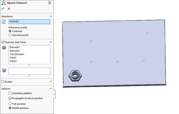
FIGURE 9.23 Using a sketch-driven pattern
The Centroid option in the Reference Point section is fine for symmetrical and other easily definable shapes such as circles and rectangles, where you can find the centroid just by looking at it; but on more complex shapes, you may want to use the Selected Point option.
Using a Table-Driven Pattern
![]() A table-driven pattern drives a set of feature locations, most commonly holes, from a table. The table may be imported from any source with two columns of data (X and Y) that are separated by a space, tab, or comma. Extraneous data will cause the import to fail.
A table-driven pattern drives a set of feature locations, most commonly holes, from a table. The table may be imported from any source with two columns of data (X and Y) that are separated by a space, tab, or comma. Extraneous data will cause the import to fail.
The X, Y origin for the table is determined by a Coordinate System Reference Geometry feature. The XY plane of the coordinate system is the plane to which the XY data in the table refers.
You can access the Coordinate System command by choosing Insert ➢ Reference Geometry ➢ Coordinate System from the menu. You can create the coordinate system by selecting a combination of a vertex for the origin and edges to align the axes. Like the Sketch Driven Pattern command, this feature can use either the centroid or a selected point on the feature to act as the reference point.
The fact that this feature is still in a floating dialog box points to its relatively low usage and priority on the SolidWorks upgrade schedule. The interface for the feature is rather crude in comparison to some of the more frequently used features. This interface is shown in Figure 9.24.

FIGURE 9.24 The Table Driven Pattern dialog box
Using the Fill Pattern
![]() The Fill Pattern feature fills a face or area enclosed by a sketch with the pattern of a selected feature or a seed cut. The type of pattern used to fill the area is limited to one of four preset patterns that are commonly used in gratings and electronics ventilation in plastics and sheet metal. These patterns and other options for the Fill Pattern feature are shown in Figure 9.25.
The Fill Pattern feature fills a face or area enclosed by a sketch with the pattern of a selected feature or a seed cut. The type of pattern used to fill the area is limited to one of four preset patterns that are commonly used in gratings and electronics ventilation in plastics and sheet metal. These patterns and other options for the Fill Pattern feature are shown in Figure 9.25.

FIGURE 9.25 Using the Fill Pattern feature
The Pattern Layout panel enables you to control spacing and other geometrical aspects of the selected pattern layout, as well as the minimum gap from the fill boundary. This is most useful for patterns of regularly spaced features with an irregular boundary.
Using a Variable Pattern
The Variable Pattern command combines techniques from the table-driven pattern with design tables. You control all the parameters of multiple instances of a table-patterned feature. The name might be misleading, because there is no actual pattern. The command just places a parametric copy of features wherever you want them.
One of the biggest distinguishing characteristics of the Variable Pattern command is that it records failed instances. The alternative is for the entire feature to fail rather than just a single instance, as will happen with other pattern features.
As you might expect with anything so powerful, there are limitations. For example, it will not allow you to pattern Hole Wizard holes or other patterns. Also, it will not accept a 3D sketch as reference geometry. Being such a highly parametric feature, the Variable Pattern command tends to be susceptible to some long-standing difficulties in SolidWorks, such as getting directions confused when spinning an angle.
Most of the examples of this function you will see around the Internet are simplistic, 2D, and don't really capture its unique capabilities, nor do they offer any compelling reasons to use it. I have two examples for you here. One is rather abstract and presented to show the concept. The other shows a slightly more plausible application. The difficulty with spinning angles is the reason most of the examples you see involve XY-grid sort of parametrics. You can get it to work, but it may be easier to do a different way. Let's start with a simple example.
Figure 9.26 shows an arrow-shaped feature, which is placed on the curvy surface at random points and rotated at various angles. The feature is always extruded normal to the surface. The Variable Pattern function enables you to simply create multiple instances of the feature, and apply different dimensions to it. It's like a design table where you have all the possible configurations at the same time.
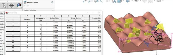
FIGURE 9.26 A simple, variable-pattern Waffle Mat.sldprt
Here is how this particular feature is set up:
- Section Plane a plane that is offset from the end of the solid by a certain dimension, D1@Section Plane.
- Intersection Sketch is a sketch with an intersection curve between Section Plane and the curvy surface, so as Section Plane moves, Intersection Sketch will undulate.
- There is a sketch point in Intersection Plane some distance (D5@Intersection Sketch) from the left edge of the solid.
- Tangent Plane is a plane that is tangent to the curvy surface at the sketch point.
- Arrow Sketch is a sketch on the Tangent Plane of an arrow that can rotate and change length, driven by an angle and a length dimension.
- Variable Pattern is a feature that can place multiple Arrow features simultaneously with various values for the following dimensions/parameters:
D1@Section Plane (position of intersection sketch)
D1@Arrow Sketch (rotation of arrow)
D3@Arrow Sketch (length of arrow)
D5@Intersection Sketch (position of tangent point)
The name Variable Pattern may be somewhat misleading, because technically, it's not really a pattern, in that there is no discernable recurring pattern; it's just a collection of several versions of a single feature in different positions and orientations.
Let's move on to a more complex but less abstract example. I will set it up the same way: several parametrically driven entities that enabled me to position, size, and orient one or more features, which are placed in any way that the parametric scheme allows. In this case, I patterned a flower around an irregularly shaped bottle.
The first try at this didn't work. Well, it worked all except getting the feature to pattern all the way around the bottle; it only worked on the front half, as shown in Figure 9.27. The error here says that “Some instances were disjoint,” which to me suggests that the Extrude features are pointing off into space instead of toward the bottle. So I simplified it by applying the same pattern to a cylinder, which could more easily be done with a circular pattern. I got the cylinder to work, as shown in Figure 9.28.

FIGURE 9.27 Patterning around an irregular shape works only on the front half, Variable Pattern Bottle3.sldprt.

FIGURE 9.28 Variable Pattern around a cylinder works all the way around, Variable Pattern cylinder.sldprt.
In the end, I was not able to get this to work 100 percent on complex geometry, and the matter has been forwarded to SolidWorks as a technical support issue. I got one row to go around the part all the way, but other rows would project the back side features onto the front, so there were no back features and double the front features. This is shown in Figure 9.29, and you can look at the file named Variable Pattern Bottle4.sldprt. I have a feeling this has to do with the overall propensity in SolidWorks to flip planes as they rotate.

FIGURE 9.29 Variable Pattern flips when driving a sketch plane.
The reason all of the Internet examples of this function are simplistic seems to be that it is not really capable of full 3D function, and this appears to expose underlying weaknesses in the SolidWorks parametric function that have been there all along. If you need to do more complex patterning, you will need to make copies of your features manually or use mirroring or more conventional patterning.
Cosmetic Patterns
Cosmetic Patterns are not patterns in the same sense as all the other pattern types in SolidWorks. The Cosmetic Patterns feature does not actually create any geometry, just the appearance of geometry. Cosmetic Pattern features are applied using RealView functionality, which may or may not be available to you depending on your hardware, in particular your video card.
Cosmetic Patterns are appropriate if your manufacturing method does not require actual geometry. For example, rapid prototyping requires explicit geometry in order to build a part, but a perforated sheet metal panel or a knurled cylindrical handle may require only a note on a drawing for the shop to set up a manufacturing process to create the geometry.
To apply a Cosmetic Pattern to a face, feature, body, or entire part, click the Appearances, Scenes, And Decals tab from the Task pane, and choose Appearances ➢ Miscellaneous ➢ Pattern Or Appearances ➢ Miscellaneous ➢ RealView Only Appearances. Drag and drop the desired pattern onto the model, and use the pop-up menu to apply it to a face, feature, body, or the entire part. Figure 9.30 shows the Appearances, Scenes, And Decals tab of the Task Manager with some of the Cosmetic Pattern options.

FIGURE 9.30 Cosmetic Pattern options in the Appearances, Scenes, And Decals tab of the Task Manager and the Cosmetic Pattern PropertyManager
Mirroring 3D Solids
![]() Because symmetry is an important aspect of modeling parts in SolidWorks, mirror functions are a commonly used feature. This is true whether you work on machine, sheet metal, injection-molded, cast, or forged parts. I discussed sketch-mirroring techniques earlier in this chapter, and now I will discuss 3D mirroring techniques.
Because symmetry is an important aspect of modeling parts in SolidWorks, mirror functions are a commonly used feature. This is true whether you work on machine, sheet metal, injection-molded, cast, or forged parts. I discussed sketch-mirroring techniques earlier in this chapter, and now I will discuss 3D mirroring techniques.
Mirroring Bodies
Earlier in this chapter, I discussed patterning bodies. I mentioned that the patterning and mirroring tools in SolidWorks do not have adequate functionality when it comes to body management (specifically the merge options). Neither tool allows the patterned or mirrored bodies to be merged with the main body if the main body is not being patterned or mirrored. Here you can see that the Pattern function has no provision whatsoever for merging bodies. The Mirror appears to have the functionality, but it applies only to bodies that are used or created by the mirror feature and ignores any other bodies that may exist in the part.
Mirroring Features
Features can be mirrored across planes or flat faces used as the plane of symmetry. If you are mirroring many features, then it is best to mirror them all with a single mirror feature rather than to make several mirror features. You may have to do this by moving the mirror feature down the tree as you add new features. Depending on your part and what you are trying to accomplish, it may be better to mirror bodies than to mirror features, but you should not go too far out of your way or model in a contrived manner to make this happen.
Mirroring Entire Parts
Often when modeling, you are required to have a left-handed part and a right-handed part. For this, you need to use a method other than body or feature mirroring. The Mirror Part command creates a brand-new part by mirroring an existing part. The new part does not inherit all the features of the original, so any changes must be created in the original part. There is an external link (remember the → symbol) that links the parts, but they must both be open to update changes. If you want different versions of the two parts, you need to use Configurations.
You can use the Mirror Part command by preselecting a plane or planar face. You should be careful when choosing the plane because the new part will have a relationship to the part origin, based on the plane on which it was mirrored. The Mirror Part command is one of the few remaining features that relies completely on preselection techniques.
The Mirror Part command is found in the Insert menu, but it is not highlighted unless a mirror plane is selected. When mirroring a part, you can bring several entity types from the original file to the mirrored part. These include axes, planes, sketches, cosmetic threads, and surface bodies. You can also bring over features and even break the link to the original file.
Mirror Part invokes the Insert Part feature, which is covered in more detail in Chapter 31, Modeling Multibodies, and Chapter 33, “Employing Master Model Techniques.”
One of the options available when you make a mirrored part is to break the link to the original part. This option brings forward all the sketches and features of the original part, and then adds a Move/Copy Body feature at the end of the tree that simply mirrors the body. Figure 9.31 shows the PropertyManager for the Insert Part feature.

FIGURE 9.31 Selecting items to bring into the mirrored part
Tutorial: Creating a Circular Pattern
Follow these steps to get practice and create Circular Pattern features:
- Draw a square block on the Top plane centered on the origin, 4 inches on each side, .5-inch-thick extruded Mid Plane with .5-inch chamfers on the four corners.
- Preselect the top face of the block, and start the Hole Wizard. Select a counterbored hole for a 10-32 socket-head cap screw, and place it as shown in Figure 9.32.

FIGURE 9.32 Start drawing a plate with holes.
- Create an axis using the Front and Right planes. Choose Insert ➢ Reference Geometry ➢ Axis. Select the Two Planes option, and then select Front and Right planes from the flyout FeatureManager. (Click the bar that says Axis at the top of the PropertyManager to access the flyout FeatureManager.) This creates an axis in the center of the rectangular part.
- Click the Circular Pattern tool on the Features toolbar. Select the new Axis in the top Pattern Axis selection box in the Circular Pattern PropertyManager. Select the Equal Spacing option, and make sure that the angle is set to 360 degrees. Set the number of instances to 8.
- In the Features To Pattern panel, select the counterbored hole. Make sure that Geometry Pattern is turned off.
- Click OK to finish the part. The result should be as shown in Figure 9.33.

FIGURE 9.33 The finished circular pattern
Tutorial: Mirroring Features
Follow these steps to get some practice and create mirror features:
- Open the
Chapter9 Tutorial2.sldprtfile from the download material. - Open a sketch on the side of the part, as shown in Figure 9.34. The straight line on top is 1.00-inch long, and the angled line ends 2.70 inches from the edge, as shown.

FIGURE 9.34 The sketch for the Rib feature
- Click the Rib tool on the Features toolbar, or select it from the menu at Insert ➢ Features ➢ Rib. Set the material arrow to go down toward the block and the thickness setting to go to the inside by .375 inches. The PropertyManager and the preview should look like Figure 9.35.

FIGURE 9.35 Applying the Rib feature
- Create a linear pattern using the rib, making the pattern reach 2 inches into the part.
- Create a chamfer on the same side of the part as the original rib, as shown in Figure 9.36. The chamfer is an Angle-Distance using 60 degrees and 0.5 inches.

FIGURE 9.36 Additional features on the part
- Create a round hole, sized and positioned as shown.
- Mirror the hole and the chamfer about the Right plane. The parametrics of the chamfer will have difficulty patterning, so you need to use the Geometry Pattern option. The finished part is shown in Figure 9.37.

FIGURE 9.37 The finished part
Tutorial: Applying a Cosmetic Pattern
Follow these steps to practice creating a cosmetic pattern:
- Open the
Chapter 9 – tutorial – cosmetic pattern.sldprtfile from the download materials for Chapter 9. - Click the Appearances tab in the Task pane. These steps work whether or not you have RealView selected.
- Expand the Appearances heading, then the Metal heading, then Steel, and then drag the Sandblasted Steel icon from the lower panel onto the part. When the pop-up menu appears, select the Part icon to apply the appearance to the entire part. Figure 9.38 shows the Task pane and the pop-up menu.

FIGURE 9.38 Applying an appearance to a part
- Expand the Miscellaneous listing (under Appearances) and the Pattern heading. Drag the Waffle Pattern onto the large cylindrical face of the part, and then Alt+click the Face icon in the pop-up toolbar. Using the Alt key while dragging or to select face, feature, body, or part automatically activates the PropertyManager to edit the appearance. Figure 9.39 shows the Appearances PropertyManager.

FIGURE 9.39 The Appearances PropertyManager
- In the Mapping tab of the Appearances PropertyManager, select the cylindrical mapping under the Mapping Style section of the Mapping Controls panel.
- Change the Rotation to 45 degrees, and choose the smallest Mapping Size.
The Bottom Line
Feature patterns and mirrors are powerful tools, but you must have some discipline to benefit from their usefulness. Patterns in particular are extremely flexible, with many types of functions and options available. You should avoid sketch patterns if possible, not only because of performance considerations, but also because complex sketches (sketches with lots of entities and relations) tend to fail more often than simple sketches.
- Master It Create an irregular sketch region on a flat face of a solid part of your choosing, add a hole inside the irregular region, and then use the Fill Pattern feature to fill the region with patterned holes.
- Master It Create a two directional linear pattern where the directions are not perpendicular to one another.
- Master It Create a pattern feature and use the Instances to Skip to remove a couple of instances of the patterned feature.