
Chapter 2
Navigating the SolidWorks Interface
The SolidWorks interface offers a wide range of tools. You'll find more than one way to do almost everything. There is no single best way to use the interface; this book generally shows the most standardized and quickest methods.
In this chapter, I start by displaying the entire default interface, but in the rest of the book, I will show only a reduced interface, mainly to save space and keep the focus on the graphics window.
After you have mastered the various interface elements and customized your SolidWorks installation, working with the software will become much more efficient and satisfying.
Identifying Elements of the SolidWorks Interface
The major elements of the SolidWorks interface are the graphics window, where all the geometry is shown; the FeatureManager, which is the list of all the features in the part; the PropertyManager, where most of the data input happens; and the CommandManager and toolbars, where you access most of the commands in the software.
Each interface element identified in Figure 2.1 is explained in detail in this chapter.

FIGURE 2.1 Elements of the SolidWorks interface
You might want to bookmark the next page and refer to Figure 2.1 often, because much of the interface discussion refers to elements illustrated in this figure. You'll never see all the interface elements shown in Figure 2.1 on the screen at the same time; this image has been composited for illustration purposes. It shows the default interface with a couple of exceptions. First, I pinned the title bar menu in place. Second, I detached the PropertyManager.
Using the CommandManager and Toolbars
In some respects, the CommandManager resembles the Microsoft (MS) Ribbon interface, but it is not a strict implementation, because SolidWorks wanted to add more customizability. In this section, I show you how to make the CommandManager work for you and how to use regular or flyout toolbars to replace it effectively.
EXPLORING THE COMMANDMANAGER
The CommandManager is an area of the interface that you can use to flip between sets of related commands. The main purpose of the CommandManager is to give you easy access to commands without cluttering the entire screen with toolbars.
The CommandManager accomplishes this by providing small tabs under the left end of the toolbar area to enable you to switch the collection of tools that appears. Figure 2.2 shows the CommandManager in Customize mode, showing all the tabs available in a default setup. To get the CommandManager into Customize mode, right-click one of the CommandManager tabs and select Customize CommandManager.
Customizing the CommandManager
The best way to get the most efficiency from the SolidWorks interface is to customize it. Notice the last tab along the bottom of the CommandManager on the right. If you want to add another tab, you can right-click this tab and select the tab you want to add. You also can select to add a blank tab and then rename it and populate it with individual buttons. Figure 2.3 shows a detail of the Add Tab menu options that opens after you right-click the right-most tab.
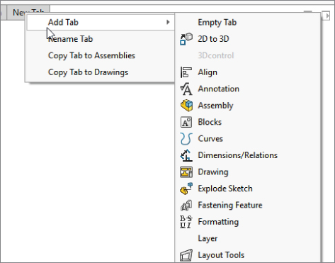
FIGURE 2.3 Adding or removing tabs from the CommandManager
To add individual buttons to the CommandManager, follow these steps:
- Choose Tools ➢ Customize from the menu bar.
- When the Customize dialog box opens, find the button you want to add.
- Click the Commands tab in the Customize dialog box, and then switch the CommandManager to the tab to which you want to add the button.
- Drag the button from the Customize dialog box to the CommandManager.
You can remove buttons from the CommandManager by dragging them into the blank graphics window area.
Docking the CommandManager
In SolidWorks, you can undock the CommandManager and leave it undocked, pull it to a second monitor, or dock it vertically to the left or right. To undock it, click and drag on any tab of the CommandManager. To redock an undocked CommandManager double-click the title area. To change its docking location, drag it onto one of the docking stations around the screen. Figure 2.4 shows the CommandManager undocked. You can also double-click on the command manager title in order to dock it back in the last parking position.

FIGURE 2.4 The undocked CommandManager with text labels
Using Auto Collapse
The small box with the arrows in it in the upper-right corner of the undocked CommandManager and the undocked PropertyManager is the Auto Collapse option. When the option is active, the PropertyManager expands and collapses automatically when your mouse goes over it. This can be very handy because it saves lots of space on the screen, but at the same time, it requires additional mouse movement to open it up. This is the common trade-off in this interface: You can trade screen space for additional mouse movement or clicks.
Mixing the CommandManager with Toolbars
To put a toolbar inline with the CommandManager, drag the toolbar close to the right end of the CommandManager. A space on that row or column opens up. The amount of space that opens up depends on the CommandManager tab with the longest set of icons, even if that tab is not showing.
Basing Tabs on Document Types
SolidWorks remembers which tabs to show on a per-document-type basis. This means that when you are working on a part document, you have one set of tabs. When you switch to an assembly document, you see a different set of tabs. The same goes for drawings. Notice that in Figure 2.3, in the right mouse button (RMB) menu, the Copy Tab To Assemblies option and the Copy Tab To Drawings option appear. These options make it easier to set up customizations that apply for all document types.
Changing the Appearance of the CommandManager
You can turn off the text in one of two ways. The easiest way to do this is to right-click in the CommandManager and deselect the Use Large Buttons With Text option, as shown in Figure 2.5.

FIGURE 2.5 Adding or removing text from the CommandManager buttons
I will use the interface with the hidden text for the rest of the book, primarily to save space on the printed page. Remember that if you need help with the name of an icon, you can hover the cursor over the icon to see a tool tip that tells you what it is.
You can scroll through the tabs of the CommandManager by pressing Ctrl+PageUp or Ctrl+PageDown. These key combinations can be controlled at Tools ➢ Customize ➢ Keyboard.
The most streamlined and space-efficient way to set up the CommandManager is to remove the text. Notice that the CommandManager without text takes up the same amount of height as a normal toolbar, with the added room for the tabs at the bottom. The text can be useful for new users or features that you do not commonly use.
The final setting for the CommandManager's appearance is the size of the icons. You have control over the size of the icon images in the CommandManager. You can find this setting in the Options flyout on the Title Bar toolbar shown in Figure 2.6. The difference between large and small icons is shown in the lower part of the figure.

FIGURE 2.6 Setting large icons
This setting applies to all the toolbar icons except the menu bar, RMB menu, and context bar icons. The setting may not take full effect until you restart SolidWorks. Large icons can be useful on displays with very high resolution; in particular, on laptops where the screen itself may be small but the resolution is very high. All the screenshots in this book are taken with the Large Icons option turned on for improved visibility.
Recognizing the Limitations of the CommandManager
If you undock the CommandManager, you cannot reorient the tabs horizontally. They remain vertical. In addition, you cannot place multiple rows of toolbars on the same row as a CommandManager using large buttons with text. You cannot dock the CommandManager to the bottom of the SolidWorks window. Another minor limitation is that although SolidWorks allows you to place toolbars at the right end of the CommandManager and above the CommandManager when the CommandManager is docked at the top, it does not allow you to place them to the left of the CommandManager or below it.
USING TOOLBARS
Interface setup is frequently about compromise or balancing conflicting concerns. In the case of the CommandManager, the compromise is between screen space, mouse travel, and clicks. You may find yourself clicking frequently back and forth between the Sketch and Features tabs. For this reason, you may find it valuable to put the Sketch toolbar vertically on the right side of the graphics window and remove it from the CommandManager. This enables you to see the Sketch and Features toolbars at the same time and greatly reduces clicking back and forth between the CommandManager tabs.
The SolidWorks interface performs best with some customization. No two people set it up exactly the same, but everyone needs some adjustment because he or she might be working on specialized functionality (such as molds or surfacing) or might work with limited functionality (such as predominantly revolved features). Of course, customization can accommodate personal preferences—for example, if one user prefers to use hotkeys and another uses menus, gestures, or the S key.
To enable or disable a toolbar, you can right-click in a toolbar area and choose the toolbar you are interested in enabling from a list of all the toolbars in SolidWorks. Another way to do this is to use the Customize dialog box by choosing Tools ➢ Customize, or the Customize option near the bottom of the RMB toolbar list. Yet another way is to choose View ➢ Toolbars.
Exploring the Heads-Up View Toolbar
The Heads-Up View toolbar appears along the middle of the top edge of the graphics window. Figure 2.7 shows the default arrangement of the Heads-Up View toolbar, and it is shown in relation to the rest of the interface in Figure 2.1.

FIGURE 2.7 The Heads-Up View toolbar
You can customize the Heads-Up View toolbar by using the Toolbars dialog box (Tools ➢ Customize ➢ Toolbars). Customization includes turning the Heads-Up View toolbar on or off and adding or removing buttons. If you have multiple document windows or multiple view ports showing, the Heads-Up View toolbar shows only in the active window or view port. This toolbar often overlaps with other interface elements when the active window is small.
Exploring the Title Bar Toolbar and Menu
The Title Bar toolbar is found just to the right of the SolidWorks logo on the title bar in the top-left corner of the SolidWorks window. By default, it contains most of the elements of the standard toolbar, and it is available even when no documents are open. It uses mostly flyout toolbar icons, so again it follows the trend of saving space at the expense of an extra click. This toolbar can be customized in the same way as other toolbars in the Customize dialog box in the Commands tab. This toolbar cannot be turned off, but you can remove all the icons from it.
There is also a Title Bar menu, which is hidden by default. The SolidWorks logo in the upper left of the SolidWorks window or the small triangle next to the logo serve as a flyout to expand the main SolidWorks menus. You can pin the menus in place using the pushpin.
Notice that on low-resolution or non-maximized SolidWorks windows, you can run into some space problems if the Menu Bar menu is pinned open. You need to examine customizations to the SolidWorks interface with display size in mind. You might consider having different sets of settings for using a laptop at a docking station with a large monitor, using the laptop with a small monitor, and using the computer with a low-resolution digital projector.
A setting exists to help you control the display for these situations. Figure 2.8 shows the View ➢ Workspace menu. This gives you the options of Default, Widescreen, and Dual Monitor. With dual monitors, you can put some elements of the interface on the second monitor to save graphics space. You will also see a Touch Mode option in the View menu, which will help you set up the display for touch screens and tablets.

FIGURE 2.8 The Workspace and Touch Mode interface settings
Looking at the Flyout Toolbar Buttons
SolidWorks saves space by putting several related icons on flyout toolbars. For example, the Rectangle tool has a button for each of the several different ways to make a rectangle, and they are all on the rectangle flyout. To see all available flyouts, choose Tools ➢ Customize ➢ Commands ➢ Flyouts.
Flyouts primarily save toolbar space when several tools are closely related. SolidWorks has set up flyouts in two configurations: flyouts that always maintain the same image for the front button image (such as the Smart Dimension flyout) and flyouts that use the last-used button image (such as the Rectangle flyout).
Exploring the Context Toolbars
Context toolbars are toolbars that appear in the graphics window and in the FeatureManager when you right-click or left-click something. When you right-click, a context toolbar appears at the top of the RMB menu and shows the functions that SolidWorks deems the most commonly used functions. The advantage of this block of tools is that because they are more commonly used, you should be familiar with the icons, so they don't need supporting text titles, as do the less commonly used tools on the RMB menu. Figure 2.9 shows the RMB menu with context bar.

FIGURE 2.9 The right-click menu and context toolbar
When you left-click an item, the context toolbar appears by itself; the rest of the RMB menu does not appear. If you do not recognize an icon on the context toolbar, you can refer to its tool tip. Context toolbars are editable in two ways. First, you can turn them off and restore the RMB menu to its complete configuration. To turn off the context toolbars, click the context toolbar and choose Tools ➢ Customize. Use the options on the right side of the main Toolbars tab. (refer to upper right corner of Figure 2.10) Second, you can add or remove icons on specific context toolbars by right-clicking the toolbar itself and selecting Customize.
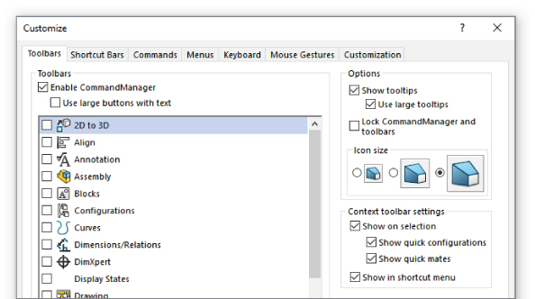
FIGURE 2.10 SolidWorks uses large tool tips by default.
The purpose of the context toolbars is to save space by condensing some commands into a toolbar without text instead of a menu with icons and text. The left-click and right-click context toolbars are the same, but they work differently. The left-click context toolbar fades as you move the cursor away from it and becomes darker as you move the cursor toward it. After it fades completely, you cannot get it back without reselecting the item.
Exploring the Shortcut (S) Toolbar
The Shortcut toolbar is also known as the S toolbar because, by default, you access it by pressing the S key. You can customize this toolbar so it has different content for sketches, parts, assemblies, and drawings. To customize the S toolbar, right-click it when it is active and click Customize from the RMB menu.
Users claim to have customized the S toolbar to such an extent that they have been able to remove the CommandManager and all other toolbars from their interface or if the Shortcut Toolbar is used in conjunction with well-customized Context Toolbars. This is possibly true if you use a limited number of sketch entities, sketch relations, and feature types, or if you make extensive use of flyouts on the S toolbar. However, if you work with a wide range of tools (say, surfacing, sheet metal, and plastic parts), you may need some additional toolbar space. It is completely believable to have access to most of the software's functions with the S toolbar and either the Menu Bar toolbar or the CommandManager. CommandManager by far gives you the most flexibility, but it also requires the most space.
The S key shortcut may conflict with another keyboard customization. To change the S toolbar key to another character or to reassign it, follow the directions for creating and maintaining hotkeys later in this chapter in the section on customization. It is referenced as the shortcut bar in the Keyboard list (Tools ➢ Customize ➢ Keyboard).
USING TOOL TIPS
Tool tips come in two varieties: large and small. Large tool tips show the names of the tools and available shortcut keys, along with brief descriptions of what they do. Small tool tips show only the tools' names and shortcut keys. To change the tool tip display from large to small, or to deselect the tool tip display altogether, choose Tools ➢ Customize. The options for sizing tool tips and showing tool tips appear in the upper-right corner. In addition to the tool tip balloons, tips also appear in the status bar at the bottom of the screen when the cursor is over an icon. Figure 2.10 provides the options for tooltips and shows a comparison between large, medium, and icons.
In addition to the tool tips, this area of the Customize dialog also controls icon size and the setting to show or hide context toolbars.
MANAGING TOOLBARS
After all that, if you still feel you need to work with standard toolbars, it is easy to move, select and deselect, and add icons to toolbars. It is important to remember that different document types retain different toolbar settings; for example, the toolbars that you see with a part open are different from the toolbars that you see for drawings. For this reason, when you change from a part document to a drawing document, you may see your display adjust because the changing toolbars increase or decrease the amount of space that is required.
Moving Toolbars
To move a toolbar, you can click with the cursor at the dotted bar on the left-most or top edge of the toolbar. Figure 2.11 shows the dotted bar on the top edge of a toolbar. When the cursor changes to a four-way arrow, you can drag the toolbar where you want it. Toolbars dock either vertically or horizontally. You can resize undocked toolbars so they have rows and columns. This arrangement is typically used with the Selection Filter toolbar, which is often left undocked and compressed into a block that is three or four columns wide.

FIGURE 2.11 Dotted bars enable you to move toolbars.
Using Flyout Toolbars
You can use any toolbar as a flyout toolbar. Figure 2.12 shows the list of all flyout toolbars; it is the same as the list of all toolbars. To use a toolbar as a flyout, select it from the flyout toolbars list and drag it onto an existing toolbar. It displays with an arrow to the right. Clicking the arrow causes all the tools to scroll out temporarily until you click a toolbar icon or anything else.

FIGURE 2.12 The flyout toolbars are on the Commands tab in the Customize dialog box.
To add icons to a flyout toolbar, temporarily show the regular toolbar that corresponds to the flyout toolbar and add icons to the regular toolbar. When you are finished adding or removing icons, turn off the regular toolbar; the changes will be applied to the flyout. Some flyout toolbars are not available, such as the Rectangle flyout, but you can use this technique on toolbars that are used as flyouts, such as the Reference Geometry toolbar.
Working in Various Screen Configurations
Full Screen mode enables you to toggle quickly to the display so that only the graphics window and the Task pane appear. The FeatureManager, menus, toolbars, and status bar are all hidden. Alternatively, you can hide just the FeatureManager or the toolbars.
In Full Screen mode, you can still access the menus by clicking with the cursor along the top border of the window:
- F8 toggles the DisplayPane.
- F9 toggles the FeatureManager.
- F10 toggles the toolbars.
- F11 toggles Full Screen mode.
Under View ➢ Workspace, you find other screen setups, including Widescreen and Dual Monitors. Widescreen puts the CommandManager to the left of the FeatureManager, and Dual Monitors puts the CommandManager and PropertyManager on the second screen.
Controlling Menus
Everyone has his or her own style of working. For example, some people like to use menus, and others do not. Some like to use hotkeys, and others like the mouse.
Most users avoid menus because they seem like an old way of working. However, some commands, such as Modify Section View, are available only through the drop-down menus. Also, SolidWorks users who use a wide range of features wind up using the menus more often than users who use a more limited set of tools.
The most frequently used menu items are in the View, Insert, and Tools menus. All the menus shown in this section have all the possible options shown. Customizing menus is rarely done, although it is possible. To customize a menu, activate the menu and select Customize Menu from the bottom of the menu, as shown in Figure 2.13.
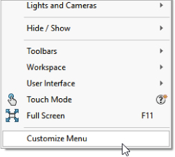
FIGURE 2.13 Access to customize a menu
You use the View menu primarily for turning visibility on or off for entity types such as planes, sketches, or temporary axes. You can also do this by using hotkeys or via the Heads-Up View toolbar.
The Insert menu is used mostly for creating feature types for which you do not have a toolbar icon on the screen. For example, although the Move Face tool is on the Mold Tools toolbar, you can also find the Move Face tool on the Direct Editing toolbar. Move Face has many uses aside from mold design. You can find the Move Face tool by choosing Insert ➢ Face.
You can customize menus by adding or omitting items. By using the Customize Menu option at the bottom of any menu—including shortcut (RMB) menus—you can remove items from any menu by clearing the check boxes next to tools you do not use. To bring back the removed items, you can go back to Customize Menu or choose Tools ➢ Customize ➢ Options and click the Reset to Defaults buttons for menu and shortcut customization.
While omitting items may not sound like much of a benefit, some of these menus are so long that they may not fit on your monitor—even a large monitor—and they may include tools that you never use. So, sometimes trimming down a menu to make it fit the interface better is a good choice for your particular situation. You may also find administrative reasons to remove certain commands from the available list (to prevent users from adding certain features to the tree).
Changing Cursors
SolidWorks cursors are context-sensitive and change their appearance and function depending on the situation. Sketching cursors display a pencil and the type of sketch entity that you are presently sketching. Sketch cursors also display some dimensional information about the entity that you are sketching, such as its length or radius. Sketch cursor feedback is necessary for fast and accurate sketching.
To learn more about sketch cursor feedback, see Chapter 3, “Working with Sketches and Reference Geometry.”
The select cursor changes depending on the item over which it is positioned. Cursor symbols also help remind you when selection filters are active. Figure 2.14 shows various cursors and their significance.

FIGURE 2.14 Various SolidWorks cursors
Working with Models in the FeatureManager and PropertyManager Windows
The FeatureManager and PropertyManager are windows in the interface where you will spend much of your time. You can manipulate the content inside the windows in various ways.
USING THE FEATUREMANAGER
The FeatureManager window is the panel to the left of the screen; it shows the features describing how the part was built. SolidWorks users spend a fair amount of time using the FeatureManager to edit or inspect models. You can use the tree (as it is known informally) to see items in the order in which they were created or to search for specific items. You can put parts or features in folders for organization. Using the Display pane, you can turn visibility on or off for bodies, parts, reference geometry, and other items. You can use it to display names, descriptions, and other metadata.
Figure 2.15 names the various parts of the FeatureManager interface.

FIGURE 2.15 The parts of the FeatureManager
Figure 2.16 again shows the FeatureManager for a simple model, this time using the options for Dynamic Reference Visualization (DRV). Parent features are typically above the selected feature, and are indicated by the blue DRV arrows. Child features are typically below the selected feature and are indicated by purple DRV arrows. (Child features can sometimes be found below the selected feature due to SolidWorks method of putting sketches below the feature. Using the shortcut Ctrl+T will switch the FeatureManager to a more literal representation of the feature order where all child features come after the parents.) You will learn more about this in Chapter 12, “Editing, Evaluating, and Troubleshooting.”

FIGURE 2.16 Dynamic Reference Visualization
The DRV enables you to instantly understand the parent/child relations between the various features in the part. The setting to enable or disable DRV is at View ➢ User Interface, as shown in the image to the right in Figure 2.16.
A splitter bar at the top of the FeatureManager (see Figure 2.15) enables you to split the FeatureManager window into two windows. This enables you to display the FeatureManager and another window, such as the PropertyManager (refer to Figure 2.17). The tab on the right of the FeatureManager (or the F9 key) can collapse the FeatureManager to save space.

FIGURE 2.17 Split FeatureManager with PropertyManager on the bottom
Looking at the Display Pane
You can open the Display pane flyout from the FeatureManager by using the arrow at the top-right corner of the FeatureManager. The Display pane helps you to visualize where appearances (colors), display styles, or hidden bodies have been applied in a part document and additional functions in an assembly document. The Display pane is helpful when you're looking for colors that are applied to the model at some level other than the part level.
Appearances are covered in more detail in Chapter 5, “Using Visualization Techniques.”
Looking at the Rollback and Freeze Bars
The Rollback bar at the bottom of the FeatureManager enables you to see the part in various states of history. Features can be added while the rollback bar is at any location. The model also can be saved while rolled back.
A bar at the top of the FeatureManager is called the Freeze bar (refer to Figure 2.15), and it locks the features that are above it from being rebuilt or edited. To enable it, go to Tools ➢ Options ➢ General. You can position it just like the Rollback bar.
Looking at the FeatureManager Filter
One of the most useful elements of the FeatureManager is the FeatureManager filter. The filter resides at the top of the FeatureManager. If you type text in the filter, SolidWorks searches feature names, descriptions, comments, tags, and dimension names for text matching the string, and it shows only matching features in the window. This also works in assemblies, where you can filter for part names or document properties. The filter is very useful for quickly finding parts, features, mates, or anything else that shows up in the part or assembly FeatureManager.
Looking at Folders
The FeatureManager allows a couple of different types of folders. One type enables you to group features together, which is especially useful when you have long feature trees and you want to put all the fillets together into one folder. It is also useful in assemblies when you want to group certain types of parts together, such as fasteners.
Another type of folder is the special-use folders at the top of the FeatureManager for things such as solid bodies, surface bodies, sensors, and Favorites. You can add features to the Favorites folders by right-clicking the feature and selecting Add to Favorites.
These special-use folders are not all turned on by default. To turn them on or off (or allow them to be turned on only if they have content), go to Tools ➢ Options ➢ FeatureManager, where you will find a list of tree items, including these special-use folders. Figure 2.18 shows a FeatureManager with several kinds of folders in use.

FIGURE 2.18 FeatureManager folders of various types in use
USING THE PROPERTYMANAGER
The PropertyManager is where you set most of the feature parameters and where you edit the properties of selected items such as sketch elements. You can manually switch to the PropertyManager using the tabs on the top of the Display pane or allow it to pop up automatically when your input is needed.
One of the benefits of putting all the data entry into the PropertyManager is that it saves lots of space on the screen. On the other hand, you will often need to make a selection from the FeatureManager at the same time the PropertyManager pops up and takes its place. You can disable this automatic pop-up behavior by choosing Tools ➢ Options ➢ System Options ➢ General and selecting the Auto-show PropertyManager setting.
My favorite option for dealing with the PropertyManager is to detach it from the FeatureManager so I can see the two side by side instead of one or the other. To detach the PropertyManager, drag its icon from the tabs out into the graphics area and release. You can see the detached PropertyManager in Figure 2.1. After the PropertyManager is detached, you can move it to a second monitor, float it within the SolidWorks window, dock it, or reattach it. To put it back in its place under the FeatureManager, just drag it back on top of the FeatureManager using one of the docking station symbols on the screen, allow it to snap into place, and release it.
You can also use the splitter bars (shown in Figure 2.1 in the upper-left corner) to put the FeatureManager on top and the PropertyManager beneath, or you can use the flyout FeatureManager. When creating or editing a feature, you can access the flyout FeatureManager by double-clicking the name of the feature at the top of the PropertyManager. The flyout FeatureManager is displayed just to the right of the regular FeatureManager, in the main graphics window; it's transparent to enable you to see the model through it. The various ways of combining the FeatureManager and PropertyManager are shown in Figure 2.19.

FIGURE 2.19 The detached PropertyManager, the split FeatureManager, and the flyout FeatureManager
INTRODUCING THE DISPLAYMANAGER
The DisplayManager helps you understand the various display-related items applied to your part or assembly. This includes lights, scenes, backgrounds, appearances, colors, textures, and decals. Figure 2.20 shows the DisplayManager with the Appearances active. Chapter 5 discusses the DisplayManager in more depth.

FIGURE 2.20 The DisplayManager helps you sort through everything that affects how the model looks.
Getting Around the Task Pane
By default, the Task pane sits to the right of the SolidWorks screen, although you can undock it entirely. If you want to keep it open, click the pushpin in the upper-right corner of the pane. The Task pane is shown in Figure 2.21. If you cannot see the Task pane, it may be turned off. You can turn it and other interface elements on or off using the View menu (refer to Figure 2.16).

FIGURE 2.21 The Task pane, Home tab
The Task pane is the home for several panels:
- Home Tab: This tab enables access to the Welcome screen as well as several miscellaneous SolidWorks tools. You can also access the Subscription Services from here.
- Design Library: This includes locally stored libraries, Toolbox, and 3D Content Central. It also contains “SolidWorks Content,” which can be downloaded directly from the Task pane.
- File Explorer: You can use this Windows Explorer interface to browse for files.
- View Palette: This palette enables you to visually select views and drag them onto a drawing sheet.
- Appearances, Scenes, and Decals: This panel enables you to select appearances and scenes for your SolidWorks documents. SolidWorks has also moved decals into the SolidWorks Standard level of the software instead of being part of the rendering software.
- Custom Properties: The Custom Property tab in the Task pane enables you to create a custom interface that goes inside this Task pane tab, which will help you enter custom property data quickly, easily, and accurately.
- SolidWorks Forum: This tab shows some of the latest comments on the SolidWorks forums. Clicking a link in this panel launches a web browser window for more convenient access.
- Recovered Documents: After a crash, auto-recovered documents are listed in this special-purpose Task pane tab.
Getting Familiar with the Status Bar
The status bar nonintrusively communicates SolidWorks information back to users, and it contains some interactive options. It is located at the bottom of the screen, and you can enable it from the View menu. Figure 2.22 shows the status bar in action.

FIGURE 2.22 The status bar showing sketch information
The status bar can display the following information, indicators, and icons:
- Progress as parts, assemblies, or drawings load
- Change units
- Tool tips feedback for commands
- Measurement results
- The sketch status for an active sketch
- In-context editing
- Suspend automatic rebuilds
- Quick Tips toggle
- Tags data-entry window toggle
- The sheet scale for drawings
- The cursor position for drawings and sketches
- Whether you are editing the sheet, sheet format, or view of a drawing
- Window expander when SolidWorks is not maximized
ASSIGNING TAGS
Tags work like document keywords. Tags can be searched using either SolidWorks Explorer or the FeatureManager Filter. You can assign tags by clicking the tag icon in the lower-right corner of the SolidWorks status bar. (Refer to Figure 2.1.)
Using SolidWorks Search
You can find SolidWorks Search in the upper-right corner of the SolidWorks application window, on the title bar, as shown in Figure 2.23. This is different from the FeatureManager Filter, which enables you to search within a part, assembly, or drawing for feature names or other types of data.

FIGURE 2.23 SolidWorks Search options
SolidWorks Search enables you to search the SolidWorks Help, Knowledge Base, commands, or community forums for information (some of these require an Internet connection and login) and to look for SolidWorks models on your local or network drives.
SEARCHING FOR FILES
The file searches include 3D ContentCentral, SolidWorks Explorer, and SolidWorks PDM, if it is installed.
To configure where SolidWorks is going to search for files, you can use the options at Tools ➢ Options ➢ File Locations ➢ Search Paths. Remember that SolidWorks follows search rules that force it to look in directories that may not be obvious to you, including recent folders where you have saved documents and other directories.
You also can select custom properties to search from the drop-down list.
Making the Interface Work for You
As engineers and designers, we all like to tinker with things to optimize efficiency and to apply our personal stamp. When the SolidWorks software is installed, the interface is functional, but not optimal. Earlier in this chapter, I discussed managing and customizing toolbars and menus. In the remainder of this chapter, I will focus more on customizing the interface and suggest some strategies that you might use to help customize your work environment.
Customizing Colors
Before you change the standard colors in the SolidWorks interface, you need to be aware of a few things. The first is that SolidWorks does not automatically alter text color to contrast with your background. As a result, if you set the background to black and the text is black, you won't be able to see the text. This may seem obvious to some people, but AutoCAD automatically changes text color to contrast with the view port background, so AutoCAD users may take this functionality for granted.
Also, be aware that the colors in the SolidWorks interface have been chosen carefully to offer good contrast between elements that may be adjacent or superimposed on one another. In most cases, colorblindness has been factored in to the selections, so you probably won't see blue and green right next to one another where it matters in the interface.
EXPLORING DEFAULT SELECTION COLORS
All the interface colors are controlled in the Systems Options Colors dialog box. You can access the dialog box by choosing Tools ➢ Options ➢ Colors, as shown in Figure 2.24.

FIGURE 2.24 Controlling interface colors
Notice that you can set a color scheme. If you want to change the colors used in the interface, I recommend that you save the settings as a color scheme so the scheme can be re-created easily later or copied to another computer. Color schemes are stored in the Windows Registry, not as separate files. To transfer color settings to another computer, you need to either use the Copy Settings Wizard or manually copy data from the Windows Registry.
Before making changes, you might consider saving your initial settings as a separate scheme so you can get back to them if necessary.
SELECTING BACKGROUND OPTIONS WISELY
You should avoid some colors for the background, or you should make some changes if you choose these colors. Black is used with fully defined sketches, dimensions, FeatureManager text, and annotations. Blue can mask the underdefined sketch color and some dimensions. Bright green can cause problems with seeing selected items. Bright red, aside from being a terrible color to stare at all day, also does not contrast well with some of the red highlights and error colors. Even gray masks reference dimensions.
You might think that no matter which color background you select, aside from the default, something will become difficult to see. For this reason, many users choose a gradient or image background, which enables them to pick colors where items are always visible on one half of the screen. Staring at a white screen all day can be uncomfortable for your eyes, so pick colors that enable you to see everything with “reasonable” contrast, yet are not glaringly bright. Very high contrast is hard on the eyes, and low contrast may make it difficult to distinguish items on the screen.
You have to consider the purpose of the background. Some people doing presentations may want the background to be attractive while otherwise staying out of the way. Others may need the background only to contrast with whatever is in front of it in a way that does not strain the eyes. For writing a book, the background generally needs to be white to match the page. No one scheme will suit all needs.
In addition to colors and gradients, you can use an image as the graphics window background. This gives you a wider range of customization capabilities, and several sample images are already available in the default settings. Also, be aware that document scene backgrounds are document-specific but can be overridden by system options.
RealView also adds some capabilities with scenes. Scenes can be applied from the Appearances, Scenes, And Decals tab on the Task pane. Most of the display settings work in conjunction with RealView, which is an advanced display mode. Depending on your graphics card, your computer may or may not be capable of using RealView. SolidWorks offers three different types of scenes: Basic, Studio, and Presentation. Of these, I find the Studio scenes to be the best when I need a reflective floor with shadows; otherwise, I stick with the Basic scenes. I find it distracting to use either reflections or shadows in models while working. However, adding a nice, shiny RealView appearance to the part is often useful, especially for visualizing curvature on curvy parts.
I describe RealView, along with scenes, in more detail in Chapter 5.
Customizing Strategies
You can easily customize many aspects of the SolidWorks interface, including the following:
- Toolbars
- Menus
- Background colors or images
- Task pane location
- Hotkeys
- Macros
- Custom application programming
Whether you should customize each of these items depends partially on how much time and energy you have to spend, how much you work with others, whether you share your workstation with other users, and how much money you are ready to dedicate in the case of custom programming.
CONSIDERING HOTKEY APPROACHES
Any command that you use more than a few times an hour is worth assigning to a hotkey. I like to use alliteration when assigning keys to help with my faulty memory. The most frequently used commands are assigned single-letter hotkeys, and the less frequently used commands are assigned combinations. Thus, Tools Options is linked to O, Measure to M, Select Vertex to Shift+V, and Curve Projected to Ctrl+J. (Ctrl+P is the Windows standard for the Print command.) Some of the settings I like to use conflict with the default settings. SolidWorks has a nice mechanism to deal with entering conflicts—it will warn you of the conflict, and you can choose to proceed with the change or not. Other people like to group keys into easy-to-reach combinations; this is why the Q, W, A, S, Z, and X keys are often assigned first for right-handed mouse users.
ORGANIZING HOTKEYS
Hotkeys are assigned and organized in the Keyboard dialog box (Tools ➢ Customize ➢ Keyboard), as shown in Figure 2.25. This interface enables you to see all the hotkeys (called shortcuts in the list) easily. If you try to enter an existing hotkey, SolidWorks issues a prompt, telling you that the key is assigned to another command and its name. The prompt asks whether you want to clear the other instance of the hotkey and make the new one active. You can print or copy to the Clipboard a list of commands that use hotkeys.

FIGURE 2.25 The Keyboard dialog box (Tools ➢ Customize ➢ Keyboard)
Because the list of commands is so long, a Search function is available, and a drop-down arrow makes visible only the commands from a selected menu. The list of commands is organized by menu name, and the menus are listed as they occur in the interface. Fortunately, you can use the Keyboard tab to sort and list menus, commands, or hotkeys in alphabetical order just by clicking the corresponding column header. This is a highly usable interface and one of my favorite interface changes in the last several releases.
Hotkeys for menu items are listed on the right side of the regular drop-down menus. They serve more as learning aids than interface elements.
I have included a spreadsheet of the default hotkeys in SolidWorks 2018 with the download materials for Chapter 2. You can save the list of settings by using the Copy List button in the dialog shown in Figure 2.25. If you do a lot of customizations, it might be handy to print them out and tape them to the side of your monitor. It is a little pointless to have to refer to a chart to remember shortcuts, but you might think of it more as a training aid or a means to allow other people to use your workstation effectively.
USING MOUSE GESTURES
You can customize and use a mouse-gestures interface, shown in Figure 2.26. To make the interface appear, just drag the RMB slightly, about ¼ inch. After you get used to the interface, a drag of about ¾ inch in a single motion activates the commands.

FIGURE 2.26 The mouse-gestures interface
You can establish the donut in four or eight segments; it comes set to four by default. You can also do the customization in the Customize dialog box (Tools ➢ Customize) using the Mouse Gestures tab. The advantage of this interface is that it is very easy to invoke. I like the way you can use the default setup to control views. The mouse moving in a particular direction is easily associated with a view direction, so it should be easy to remember.
Mouse gestures will probably not replace hotkeys or the S toolbar, but they do add effective quick access for a few functions.
USING THE KEYBOARD
Moving between the mouse and the keyboard can be bothersome and time-consuming. In addition to the hotkey approach, you can use another keyboard method to save time. Many users become adept at using the Alt-key combinations to invoke menu items. Most menu items in Windows applications contain a single underlined letter.
To access a top-level menu, you can hold down the Alt key, press the underlined letter for that menu, and then just press an underlined letter in the menu to access specific commands. This decidedly old-school technique enables you to navigate most of the interface without using the mouse. For example, to exit SolidWorks, instead of using the mouse to click the red X in the upper-right corner, you could press Alt+F, X. In Figure 2.27, you can see that the F in File is underlined, as is the X in Exit.

FIGURE 2.27 Alt keys in the Window menu
You may potentially run into conflicts when using Alt keys for menu functions. A combination of Alt plus another keyboard key is valid for use as a hotkey combination. If you use any Alt-hotkey combinations, it is likely that you have seen a conflict like this. In cases of conflict, the hotkey combination seems to gain priority over the Alt-key accelerator.
MINIMIZING ICONS
In order to maximize valuable space on the monitor, many SolidWorks users strive to minimize the number of toolbar icons on the screen or confine them to two rows of toolbars. You can do this by using the CommandManager, flyout toolbars, the S toolbar, right-click and left-click toolbars, and hotkeys, and by removing unused icons, as well as the other techniques discussed here.
Having an uncluttered workspace is definitely a plus, but having easy access to commands is the real purpose of an interface in the first place. You need to strike a balance between too much and not enough. The more kinds of work you do in SolidWorks, the more tools you will need to have available. If you create only relatively simple, machined parts and drawings, you will need fewer tools available than someone who creates complex plastic part assemblies with rendering and animation.
CONTEMPLATING DEVICE APPROACHES
If you have never used a 3D mouse or equivalent view-manipulation device, you should consider it. They are wonderful devices and do far more than just spin the view. Most of the devices also have several programmable buttons that you can link to menu items. They can move drawing views, move parts within assemblies, and even manipulate selected objects in other Office applications and Web browsers. You can, from time to time, find these devices on auction sites. Be careful, however, since the older devices use serial ports rather than USB connectors.
Mice are the standard input device, and many of them are recommended for CAD work, but you might also consider a trackball. I've been using a Kensington Slimblade trackball for several years in CAD and normal office computing, and it takes up a lot less space on the desk. It does take some time to get used to it. It is wired, but it doesn't move around.
USING TOUCH AND MULTI-TOUCH SUPPORT
I have written portions of this book on a tablet PC. A tablet might not be ideal for long periods of SolidWorks usage, but I use it regularly for presentations and even modeling when I really want to get the feel of drawing a line by hand. The stylus is not quite as intuitive as a pencil, but it is less of an impediment to the tactile feel of actual drawings than a clunky mouse. Tablets are a great option when used in combination with the touch functions in SolidWorks, such as mouse gestures.
The mouse-gestures functionality is considered a tool well-suited to a tablet interface, where flicking the stylus is easier than mouse clicking. This is a single-touch technique, because the stylus typically adds only a single point of contact with the screen.
SolidWorks 2018 has added a new Touch mode, enabled via View ➢ Touch Mode. Touch mode changes the size of interface elements to make them easier to select, and it also adds a Touch Mode toolbar, as shown in Figure 2.28. The tools on the toolbar are Escape, Shortcut to the S menu, Multi-select (like pressing Ctrl), Delete, and Lock 3D Rotate, to prevent view rotations while sketching.

FIGURE 2.28 The Touch Mode toolbar
Multi-touch devices are becoming more widely available in CAD-worthy configurations, including the Microsoft Surface Studio, a full-size touch display that can be set up horizontally like an old drafting board or used vertically like a large monitor. In preparation for this future functionality that seems ideally suited to visual applications such as CAD and 3D, SolidWorks has added functionality to take advantage of these tools. Multi-touch Action Mappings, as the SolidWorks Help refers to them, are intuitive two-finger motions that enable you to control the view for actions such as these:
- Zoom in or out
- Rotate
- Pan
- Roll
- Zoom to fit
- Right-click
Accessing the Pen and Touch Interfaces
![]() The Pen tool is found on the Sketch Ink toolbar. It enables you to create freeform strokes as a feature within a sketch. Pen is used in conjunction with the Pen Sketch and Touch tools on the Sketch toolbar.
The Pen tool is found on the Sketch Ink toolbar. It enables you to create freeform strokes as a feature within a sketch. Pen is used in conjunction with the Pen Sketch and Touch tools on the Sketch toolbar.
This topic will be covered in more depth in Chapter 6, “Getting More from Your Sketches.”
ACCESSING MACROS
A macro is a short snippet of programming code that has a particular function. Most macros are small and intended for simple tasks that are repeated many times, such as changing selected dimensions to four decimal places or zooming the screen so it is sized 1:1 (actual size). Macros may be recorded, be written from scratch, or be a combination where you record a particular action for use as a starting point and then embellish it manually from there. Recorded macros may not always record the parts of the action that you want to make into a macro, but you can edit them manually to include anything that you can program with the SolidWorks API (application programming interface), which is included with the base SolidWorks package at no extra cost.
To access macros by using hotkeys, follow these steps:
- Make a folder in your SolidWorks installation directory called “macros.”
- Copy macros into this folder.
- Start (or restart) SolidWorks.
- Choose Tools ➢ Customize ➢ Keyboard.
- Scroll to the bottom of the list under the Macros category, and assign hotkeys as you would for standard SolidWorks commands.
Whether you are skilled at writing or recording macros, or you are just using macros collected from other people, they can be huge time-savers and offer functionality that you would not otherwise be able to access. You might want to consider joining the SolidWorks Community to share macros and other work with other users. The SolidWorks Community can be accessed through the Task pane within the SolidWorks software or via the SolidWorks website.
SAVING CUSTOM INTERFACE SETTINGS
After you have set up your menus and toolbars, worked out all the custom colors, figured out your hotkey usage, and connected your macros, you won't want to lose these settings when you reinstall the software or move to a different computer. Another user may want to share your settings, or you may want to transfer them to your home computer (for modeling the new deck or the doghouse, of course). Fortunately, these settings are very portable.
You can use the Copy Settings Wizard to save these settings to a file. Access the wizard by choosing Start ➢ SolidWorks 2018 Tools ➢ Copy Settings Wizard. This creates a file with asldreg file extension. You can restore settings by double-clicking this file on a computer that has SolidWorks installed on it.
The SolidWorks settings are actually Windows Registry settings. The file that is saved by the wizard is just a Registry file that has a different extension to prevent it from being applied too easily. Saved Windows Registry files have a reg file extension, and you can integrate them into the Registry by simply double-clicking them. If you are not familiar with the Windows Registry, you should not make direct changes, because even small changes can cause serious problems with your operating system, installed software, or even hardware. The settings that are saved by the Copy Settings Wizard are safe to transfer between computers. In order for the Copy Settings Wizard to work, you need to have Administrator-level access to your computer. The Copy Settings Wizard is shown in Figure 2.29.

FIGURE 2.29 The Copy Settings Wizard
Working with Multiple Document Windows
You may sometimes have the luxury of working on a single part at a time, but more often, you will find yourself with several documents open at once. This is a common situation for most users. Fortunately, SolidWorks has several methods for dealing with “information overload” to help you sort through it all.
GETTING THE MOST FROM THE OPEN COMMAND
![]() The Open dialog box presents some options that you will learn more about in later chapters. Figure 2.30 shows this interface.
The Open dialog box presents some options that you will learn more about in later chapters. Figure 2.30 shows this interface.

FIGURE 2.30 The Open command interface
You can use the Open dialog box just as you would use an open Windows Explorer window. That means you can copy, paste, rename, delete, and move files while you are deciding which one to open. You can also show a preview window and control the size of the icons. The SolidWorks-specific controls you may use most are the Quick Filter controls to narrow the display to just the types of files you're seeking. The icon to the far right of the Quick Filter list shows only top-level assemblies (assemblies that are not a subassembly in another assembly).
If you have other types of files to open, you can use the Custom button for the traditional SolidWorks file type list.
Also notice the Mode button. This button allows you to open a part in Resolved (normal, editable) mode or Quick View (view only). Configurations and Display State buttons are topics covered in later chapters—they allow you to more quickly access the information you are looking for rather than having to open the file and then switch to a different configuration.
MANAGING OPEN FILES
Pressing the combination Ctrl+Tab brings up the Open Documents window, shown in Figure 2.31. To keep the window open, continue to hold down the Ctrl key. Press Tab again to cycle through the open documents. Use the mouse to click an X in any of the thumbnails to close that document. You also can click a link to show that document in its own folder. To close the preview without changing documents, you can press Esc; however, Ctrl+Esc opens the Windows Start menu.

FIGURE 2.31 Ctrl+Tab displays all the open documents.
MANAGING RECENT DOCUMENTS
The list of recently used documents is available from the File menu or by pressing the R hotkey. This is actually just a tab in the Welcome dialog, which is also available by pressing Ctrl+F2. The Recent file list can also be accessed using File ➢ Open Recent, which gives a text-based list. The documents within the window can be opened or pinned in place so they always remain on the Recent Documents list. Figure 2.32 shows this dialog box.

FIGURE 2.32 Pressing R accesses the Recent Documents tab of the Welcome dialog.
The Folders option at the top gives you a view of the paths to all of the recent documents, and the Browse button takes you to a Windows Explorer view of the folder.
If you hover over an icon in the Documents list, a small double arrow appears in the lower-right corner of the icon. Clicking on that double arrow displays certain information and allows you to open that document in particular configurations, particular display states, open as read-only, or access the references. This is shown in Figure 2.33. A lot of capability is packed into this Welcome box.

FIGURE 2.33 More functionality behind the Recent Files list icons
MANAGING WINDOWS
Like most Windows applications, SolidWorks can arrange the open document windows in one of several ways that are available through the Window menu:
- New Window: Opens a new window of the active document. Dynamic highlights and selections in one window appear in both.
- Cascade: This is most useful for accessing documents that are to be edited one-by-one.
- Tile Horizontally: This is most useful for comparing wide and short parts side-by-side.
- Tile Vertically: This is most useful for tall, narrow parts or documents where you want to compare items in the FeatureManager.
- Arrange Icons: When windows are minimized to icons, this menu selection arranges the icons neatly, starting in the lower-left corner of the window.
- Close All: Closes all open windows. This option may prompt you to save modified documents.
SPANNING MULTIPLE MONITORS
SolidWorks has tools to help you manage the display across multiple monitors. Figure 2.34 shows the document and application window control buttons in the upper-right corner of the SolidWorks window. In addition to the usual Minimize, Maximize, and Close, the application window controls add the Span Displays tool, which makes the SolidWorks window use both displays in a dual display arrangement.

FIGURE 2.34 Multiple monitor controls
The document window controls add Tile Left and Tile Right, which force the current document window onto the left or right monitor, respectively. When accessing the Tile Left/Right icons on a single monitor, the documents will be sent to the left or right half of the screen. Multiple monitors work best if they have the same vertical resolution; for example, a 1920 × 1200 wide screen and a 1600 × 1200 normal aspect-ratio monitor would work well side by side, but mixing with a 1024 × 768 screen would not. When monitors of different vertical resolutions are used, SolidWorks sizes to the lowest resolution monitor (the second number listed is the vertical resolution).
The Bottom Line
- Learn the different parts. The SolidWorks interface has many elements because SolidWorks has so much functionality. You can access most elements multiple ways, which can be liberating because it offers options, but it can also add to the confusion because there is so much to know. You do not need to know every way to do everything; you only need to know the best way for you.
- Master It Identify each area around the SolidWorks window.
- Customization is key. Customization opportunities in SolidWorks are vast. Everyone has different tastes and preferences when it comes to running the interface. Some prefer the keyboard, some the mouse. Some prefer the touch interface. There are different strategies that depend on your specific situation—for example, saving space, saving mouse travel, or saving mouse/keyboard clicks. SolidWorks has touch interface options, as well as various accessibility tools intended to accommodate special needs, such as different input devices or color blindness.
- Master It Create some simple keyboard shortcuts (hotkeys) for the functions you think you will use the most.
- Manipulate multiple windows. Manipulating multiple windows is important in all computer use, but especially in CAD, where you work with enormous amounts of data and numbers of documents that surpass other types of programs.
- Master It Open several sample documents from the Wiley download data and practice manipulating the windows.