
Chapter 39
Using Mold Tools
The SolidWorks Mold tools give you a process by which you can take parts designed for the injection molding process and split cavity and core blocks for them, as well as additional core pins or slides. This process often requires manual intervention.
To work with the tools in this chapter, you must understand how surfaces work. Features such as the Boundary Surface, Knit, Trim, and others are covered in Chapter 32, “Working with Surfaces.”
This chapter introduces you to both the formal Mold Tools process and the less-formal manual Mold Splitting methods used in the industry.
Working with the Mold Tools Process
The goal of the Mold Tools process is to start with the CAD data of a part engineered for molding, and from that data, produce geometry that can be used to create the cavity and core for injection molding that part. Figure 39.1 shows a solid block with a cavity and a parting surface, along with the individual blocks created by the split.

FIGURE 39.1 Visualizing the goal of splitting a cavity/core block
The tools and process are generic enough that you could use them to create casts, forging dies, powder metal dies, and tooling for most plastic forming processes. SolidWorks doesn't provide libraries or functionality for building the entire mold or mold components. Mold tools require you to follow a semiautomatic process, with the tools appearing on the toolbar in the order in which they are intended to be used, from left to right.
Mold tools rely heavily on surfacing and require a fair amount of manual intervention for certain types of parts. The first half of this chapter deals with the semiautomatic process—the way it is supposed to work. The last half of the chapter deals with the manual side of the process—the way things really work with day-to-day models.
The general workflow for using Mold tools to create cavity and core blocks for a mold is as follows:
- Create split lines on the as-designed plastic part to add draft where needed.
- Create draft as needed.
- Scale the part up to compensate for shrinkage during molding.
- Identify the parting lines that separate cavity faces from core faces.
- Create shut-off faces, which are surfaces that close any through holes in the part and represent places where the steel from the cavity side of the mold directly touches steel from the core side of the mold. These openings in the part are capped by Surface features.
- Create parting surfaces. These are the faces outside the part where the steel from opposite sides of the mold touch.
- Create the tooling split. The Tooling Split feature uses the faces of the shut-offs and parting surfaces and the faces of either the cavity or the core side to split a block into two sides.
- Create any core features. In SolidWorks, the word core refers to the material used to make core pins, side action, slide, lifter, or pull in a mold.
With the formal SolidWorks process, you start in the part file with just the final plastic part in it and then build both the cavity and core blocks around the plastic part. You also build any side actions or core pins within the part file. This uses a master model approach.
Figure 39.2 shows the part of the Mold Tools toolbar that identifies the process. This toolbar also includes many surfacing and plastics analysis tools, but only the tools directly related to the Mold Tools process are shown in Figure 39.2.

FIGURE 39.2 The Mold tools
Mold tools are really meant for tooling engineers, but part designers often use the first part of the process to apply draft to parts. Tooling engineers often need to add or correct draft to the plastic parts they receive from part designers when these parts are without draft or aren't designed with any process in mind.
If you were to create a mold with manual modeling functions, you might go through roughly the same steps in the same order. The SolidWorks process often runs into problems in the automated surface modeling areas, such as shut-offs and parting surfaces. You may need to intervene in the process manually for these steps. Fortunately, the SolidWorks process is flexible enough to allow manual modeling as needed.
Each of these process steps may have several steps of its own. The process of creating a cavity and core is far from a push-button operation, but when you understand the overall process, the detailed steps become clearer.
Preparing the Plastic Part for Mold Tools
The Mold Tools process formally starts with identifying edges as parting lines. Before you get to that point, you must do some things to the plastic part model, such as shelling the part, creating draft, and accounting for shrinkage.
For this example, you'll use a part, shown in Figure 39.3, from the download files. This part uses a master model technique to create multiple parts from a single surface model, and then it's inserted into a new part for the Mold Tools process, so three levels exist for the part. The one you're concerned with in this example is called Mold Tools medical device.sldprt, which contains a single feature: an inserted part called Medical Device Frame.sldprt.

FIGURE 39.3 The plastic part for the example in this chapter
SHELLING THE PART AND APPLYING DRAFT
Shelling and applying draft to a plastic part isn't something you can cover in a couple of paragraphs. Shell and Draft features, including the evaluation techniques to determine the wall thickness, direction, and amount of the draft that was applied, are covered in detail in Chapter 38, “Using Plastic Features.”
ADDING THE PLASTIC PART TO A BLANK PART
The Mold Tools process works in Multibody mode rather than in Assembly mode. This makes sense as long as you don't start by putting all the Mold Tools features into the same file that contains all the Plastic Part features. This would make a single part with many features that exist for different purposes.
When you're preparing a part for Mold tools, the best practice to follow is to insert the designed plastic part into a new part using the Insert Part feature at the top of an empty new part. This does a couple of things. First, it separates the rebuild time for the Mold Tools from the rebuild time for the plastic part. In addition, if you're just working on the plastic part, you don't want to have to worry about the Mold Tools features. Second, it separates the features of the Mold tools so you're not working with the live plastic part data when all you need is the final geometry.
This step is just a recommended part of the process that has been added; it isn't part of the process that SolidWorks has established for the tools, but you'll probably find it useful.
USING THE SCALE FEATURE
![]() The Scale feature is used to make the plastic part slightly larger to compensate for plastic shrinkage during molding. Scale is driven by a multiplier value, so a part that's twice as big gets a scale factor of 2, and one that's half as big gets a scale factor of 0.5. Plastic materials have a shrink rate that's usually measured in thousandths of an inch of shrink per inch of part. Five thousandths inch per inch is equal to a 1.005 scale factor. If the part is 4 inches long, the mold cavity to produce it must be 4.020 inches with that material.
The Scale feature is used to make the plastic part slightly larger to compensate for plastic shrinkage during molding. Scale is driven by a multiplier value, so a part that's twice as big gets a scale factor of 2, and one that's half as big gets a scale factor of 0.5. Plastic materials have a shrink rate that's usually measured in thousandths of an inch of shrink per inch of part. Five thousandths inch per inch is equal to a 1.005 scale factor. If the part is 4 inches long, the mold cavity to produce it must be 4.020 inches with that material.
Some materials have anisotropic shrink rates, meaning they shrink different amounts in different directions, with the primary direction being considered the direction of the molten plastic through the mold cavity. SolidWorks has a means to compensate for this, although it may not always be practical. Usually the shrink directions are identified as in the direction of flow or across the direction of flow, and the direction of flow of molten plastic inside a mold cavity isn't always a straight line. Any anisotropic shrink applied to a part in SolidWorks is an approximation at best. If you deselect the Uniform Scaling option in the Scale feature, SolidWorks enables you to set different scale factors for X, Y, and Z directions. The Scale PropertyManager is shown in Figure 39.4.

FIGURE 39.4 The Scale PropertyManager
Where you should put the Scale feature is debatable. Some people argue that it should be placed in the plastic part file, so it's ready to create the mold geometry. Others believe it should be placed in the part file in which the Mold tools are created, because you might design a mold for polypropylene differently from a mold for 20 percent glass-filled nylon—so the mold is at least in some ways specific to the material.
This is where the story begins for the medical device example. Follow these steps to scale the part:
- Start a new part, and as the first feature, create an Insert Part feature. Use the
Chapter 39 - Handle Main Body.sldprtfile in the download materials. - Delete the top and bottom bodies from the inserted part.
- Scale the part about the origin. Figure 39.5 shows the FeatureManager and PropertyManager for the new feature.

FIGURE 39.5 Adding a Scale feature to start the Mold Tools process
Inserting Mold Folders
![]() The first step in the process of using SolidWorks Mold tools is to insert Mold folders. Mold folders are subfolders in the FeatureManager that the Mold tools add under the Surface Bodies folders. You can add these folders manually using the Insert Mold Folders button on the Mold Tools toolbar. They are used to organize the different groups of faces used in separating the cavity and core solid bodies. The folders that are added are shown in Figure 39.6.
The first step in the process of using SolidWorks Mold tools is to insert Mold folders. Mold folders are subfolders in the FeatureManager that the Mold tools add under the Surface Bodies folders. You can add these folders manually using the Insert Mold Folders button on the Mold Tools toolbar. They are used to organize the different groups of faces used in separating the cavity and core solid bodies. The folders that are added are shown in Figure 39.6.

FIGURE 39.6 Adding the Mold Tools folders to the Surface Bodies folder
Parting Lines
![]() The Parting Lines feature identifies (semiautomatically or manually) the edges that separate the cavity faces from the core faces. Follow these steps to establish the parting line around the part.
The Parting Lines feature identifies (semiautomatically or manually) the edges that separate the cavity faces from the core faces. Follow these steps to establish the parting line around the part.
- Click the Parting Lines toolbar icon in the Mold Tools toolbar.
- With the first selection box in the Mold Parameters panel active, select the Right (YZ) plane and make sure the arrow is pointing in the direction of pull for the inside of the part, as shown in Figure 39.7.

FIGURE 39.7 Setting the Mold Parameters for the parting lines
- Set the draft angle to 1 degree, which is the minimum angle allowed for this mold. In practice, the minimum draft applied to this mold is 1 degree, so you could use .5 degrees here.
You should have done the draft analysis before getting to this point so that you aren't depending on this analysis to make sure everything is okay. For example, this draft analysis inside the Parting Line PropertyManager cannot tell you how many faces need draft.
- Select an edge that is between a green and red face. The wavy edge along the finger grip area is a good one. SolidWorks cannot identify the parting line as the set of all edges that share green and red faces, so you'll perform this step semiautomatically.
The easiest way to do this is to click the wavy edge and then click the Propagate tag that appears as shown in Figure 39.8.

FIGURE 39.8 Propagating the parting-line edge selection
This propagating selection should select all the parting-line edges automatically, and it does, but in the example shown in Figure 39.9, it also selects some redundant edges. SolidWorks labels the redundant edges on the screen to help you see which ones need to be deselected. Notice that the message box at the top of the Parting Line PropertyManager tells you that the feature is not yet ready.
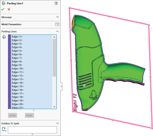
FIGURE 39.9 Correcting redundant selections
After deselecting the redundant edges, the message box in the PropertyManager turns yellow, because the Parting Line feature doesn't split the mold. In this case, the part has screw holes that go through the part, so you need to create shut-off surfaces to close them. However, you're now done with the Parting Line feature. Remember the tools to select edges; manual selection, Propagate, the Yes/No toggles, and so on. You may have to use one or more of these tools to complete the task.
- Click the green checkmark icon to accept the feature.
Thirty-five edges should be selected in the Parting Lines selection box.
Initiating the Shut-Off Surfaces
The mold industry is full of terminology that may not be familiar to some designers. Shut-offs, in mold lingo, are just locations inside the mold where the two sides of the mold dies touch one another. Shut-offs in the mold usually create holes within a plastic part. The shut-off surface—where the steel from one side of the mold touches the steel from the other side of the mold—is usually flat. Shut-off faces touch each other with significant pressure, so they are usually flat and perpendicular to the clamp force so they don't induce lateral forces. However, angled shut-offs can exist, and passing shut-offs are highly angled—as much as 80 degrees or so.
![]() The screw holes that go through the plastic part require shut-off faces in order to create the mold cavity and core. You can't just seal off any end of the holes; you must pay attention to which end of the hole is where the drafts in opposite directions meet. In this case, the counterbored holes from the outside must be drafted from the outside, so they must be sealed or shut off from the inside.
The screw holes that go through the plastic part require shut-off faces in order to create the mold cavity and core. You can't just seal off any end of the holes; you must pay attention to which end of the hole is where the drafts in opposite directions meet. In this case, the counterbored holes from the outside must be drafted from the outside, so they must be sealed or shut off from the inside.
When you initiate the Shut-Off Surfaces feature, SolidWorks identifies some of the necessary shut-offs for you, as shown in Figure 39.10.

FIGURE 39.10 Creating shut-offs
To use the Shut-off Surfaces feature, follow these steps:
- Click the Shut-Off Surfaces toolbar icon on the Mold Tools toolbar. SolidWorks should automatically select the inside edges of any screw holes, but there aren't any in this part.
- Locate the slanted ventilation slots in the plastic part, right-click the edge of one of them, and choose Select Tangency from the RMB menu. Four edges are added to the list box for each slot, and there are five slots.
When all 27 edges are selected, the message box at the top of the Shut-Off Surface PropertyManager turns green, as indicated in Figure 39.10.
- Ensure that the center option (All Contact) is selected in the Reset All Patch Types section before you finish.
- When you are satisfied with the results, make sure the settings match those in Figure 39.11, and click the green checkmark icon to accept the feature.

FIGURE 39.11 The default parting surface on the medical device part
When all the appropriate edges around all the holes and slots are selected, the Shut-Off Surfaces PropertyManager message window turns green and displays the message, “The mold is separable into core and cavity.”
The tags on the loops in the graphics window display the text “No Fill,” “Contact,” and “Tangent.” The No Fill condition means that you do not want SolidWorks to create the shut-off surfaces. You'll do these manually. Sometimes shut-off surfaces require complex or multifeature shut-offs, which you must do manually. The Contact condition means that the shut-off surface just needs to touch the edges, usually at a right angle. The Tangent option creates a surface that's tangent to the surrounding faces all the way around.
Sometimes you need a combination of conditions in a single shut-off, in which case you must finish the feature manually. When the parting line and shut-off surfaces are complete, SolidWorks automatically knits together all the surfaces in each Cavity and Core folder into a single surface body.
Parting Surface
![]() The Parting Surface feature in SolidWorks Mold tools works best on planar parting lines that are convex all the way around. On the sample medical device part used in this chapter, Figure 39.11 shows what SolidWorks makes of the parting surface.
The Parting Surface feature in SolidWorks Mold tools works best on planar parting lines that are convex all the way around. On the sample medical device part used in this chapter, Figure 39.11 shows what SolidWorks makes of the parting surface.
It's a mess. Therefore, SolidWorks isn't going to create the entire parting surface for this part automatically.
USING THE MANUAL OPTIONS
From the disappointing result shown in Figure 39.11, you can just change to Manual mode and change the Parting Surface distance to 1 inch.
In Manual mode, you drag the pink dots around the black rectangle until the resulting surface makes sense. The pink dots are like connectors in a Loft feature. At some point, SolidWorks will display a black dot on the black rectangle, which is where the pink dot should snap. Why the software knows this now and not before is a little baffling, but at least it gives you the option to semiautomatically fix this surface.
To get this to work, you must arrange the pink dots around the perimeter such that none of the black lines overlap one another or the part to be molded. In the area where the inset face curls around the bottom of the part, this becomes difficult and causes SolidWorks to create bad faces. If you are doing this exercise on your own, try to arrange the pink dots as shown in Figure 39.12. If you see a gap in the surface along the edge or a place where it appears to overlap itself, this will cause an error in the finished surface. This isn't an ideal method for creating tooling surfaces, but it does work.
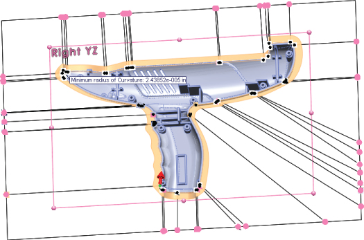
FIGURE 39.12 Using Manual mode
There are still some things to change here, and every mold designer might do this differently. You can even stop using the SolidWorks process and create the surface using your own methods if you choose.
REPAIRING THE MANUAL MODE PARTING SURFACE
To repair the surface made in the previous procedure, follow these steps:
- Use Delete Face (with the Delete option) to delete portions of the parting surface that will not work to split the mold. Delete Face can be found on the Surfaces toolbar or through the menus at Insert ➢ Face ➢ Delete.
- When you delete the face, right-click the Parting Line feature in the FeatureManager and hide it.
- Start the boundary surface from the Surfaces toolbar and fill in the missing gaps in the parting surface with Boundary, Loft, or Planar Surface features.
- You should finish with a surface as shown in Figure 39.13.

FIGURE 39.13 The completed boundary surface
The last thing that needs to be done to the parting surface is to knit it together into the core surface and the cavity surface. Follow these steps to accomplish this:
- Use Knit to knit together the boundary surface and the parting surface body resulting from the Manual Mode process.
- Make sure this knit surface goes into the Parting Surface Bodies folder, as shown in Figure 39.14.

FIGURE 39.14 The completed parting surface and feature tree
The parting surface is larger than you need it to be, and it's not a pretty shape, but neither of those issues matters.
Tooling Split
![]() Assuming you have completed the parting surface either manually or through the SolidWorks Mold tools, the next step is the tooling split. If you complete the parting surface manually, make sure it's knit together as a single surface body, and then in the Surface Bodies folder, drag the knit surface into the Parting Surface folder. The Tooling Split feature doesn't work unless all the surface bodies are in their correct folders.
Assuming you have completed the parting surface either manually or through the SolidWorks Mold tools, the next step is the tooling split. If you complete the parting surface manually, make sure it's knit together as a single surface body, and then in the Surface Bodies folder, drag the knit surface into the Parting Surface folder. The Tooling Split feature doesn't work unless all the surface bodies are in their correct folders.
Initiate the Tooling Split feature and select a planar face, approximately the parting plane. SolidWorks doesn't give you very good instructions about what it expects, but next you should sketch the mold insert block, which is typically rectangular, square, or circular, and centered on the molded piece. If this is a multicavity mold, make something you can pattern later. Once you have created and exited the sketch, the software will start to extrude it and send you to the Tooling Split PropertyManager, shown in Figure 39.15, where you can preview the feature. The feature produces two solid bodies, representing the cavity and core blocks of the mold. This model is included in the download material for this chapter.

FIGURE 39.15 The Tooling Split PropertyManager and the finished product
Make the block size approximately 4 inches on each side of the mold. Notice how the PropertyManager has picked up the surface bodies from each of the Core, Cavity, and Parting Surface folders.
When you accept the feature, SolidWorks splits your solid mold block into two using the parting surface. This is where some of your multibody and assembly visualization skills will become useful, as shown in Figure 39.16.

FIGURE 39.16 Visualizing the cavity between blocks and the parting surface
A tooling engineer would certainly change a few things about the layout of this split, but for learning how the tools work, this is sufficient. From here, you might want to continue to add gates, runners, sprue, and so on. To send the cavity and core blocks to a shop for mold building, you probably want to separate the multibody part into individual part files.
Using the Core Feature
![]() The following example is a version of the previous example that included the screw bosses. It uses the Core feature to create a set of core pins. All the standing steel that creates the counterbores for the screw bosses is made from separate replaceable pins. You can use many techniques to locate pins rotationally. This isn't a lesson in mold design—only in mold modeling techniques.
The following example is a version of the previous example that included the screw bosses. It uses the Core feature to create a set of core pins. All the standing steel that creates the counterbores for the screw bosses is made from separate replaceable pins. You can use many techniques to locate pins rotationally. This isn't a lesson in mold design—only in mold modeling techniques.
You can either create a sketch beforehand or just make a sketch when the Core feature asks you for it. The Core feature is looking for a sketch that will cut out the block of mold material from which you want to make a core. Again, you can use this for side cores or core pins. In this case, you'll make several core pins.
To start, activate the Core feature; then sketch circles centered on each of the screw boss cores in the cavity body. When you exit the sketch using the Confirmation Corner, SolidWorks will prompt you for an extrusion depth for the sketch to create the feature. The Core PropertyManager and the feature preview are shown in Figure 39.17.

FIGURE 39.17 The Core feature
Again, you can save these core pins as individual part files. You can use similar techniques to create side cores, lifters, or other types of side actions.
Working Manually with Mold Tools
You can conduct the entire mold modeling process manually, without using any of the semiautomated tools from Mold tools. You may even come across situations where you don't need to use surface modeling at all. These situations will often involve parts with a planar parting line, with no shut-offs or cores.
Experienced mold designers tend to use different techniques, from cutting away chunks with solids to using all manual surfacing methods to using about 80 percent Mold Tools techniques and manual surfacing for the other 20 percent.
You'll next run through two examples of manually intervening in the Mold Tools process. In the first, you will learn how to create a passing shut-off, and in the second, you will learn how to create the parting surface.
Passing Shut-Offs
Plastic Snap features are often created in molds by using passing shut-offs rather than some sort of lifter or horn pin slide. Eliminating actions from a mold can be economical, as long as the passing shut-off doesn't introduce wear or alignment problems. When you’re creating parts that require this sort of feature in the mold, consult your mold builder.
Passing shut-offs can be difficult to visualize. It might be helpful to open the part passing shut off.sldprt shown in Figure 39.18 and study the geometry.

FIGURE 39.18 A part that requires passing shut-offs
Two pairs of passing shut-offs are modeled in this part.
Using the Part Reviewer (Tools ➢ SolidWorks Applications) is probably the best way to see what's going on with this part. You will also need to use Ctrl+Shift+Tab and Tab to hide/show solid and surface bodies. Looking at the part and studying the steps involved will help you learn and understand. The basic steps to create the surface body called Shut-off 1 are as follows:
- Create a ruled surface for the planar edges.
- Loft surfaces between the parting line edges and the ruled surface.
- Extrude a flat shut-off face at the parting line of the Snap feature.
- Use the cavity or core knitted body to trim the extruded surface.
- Use the extruded surface to trim the ruled and lofted surfaces.
- Knit the surface bodies together.
The hardest part of creating this passing shut-off is visualizing what the interface between the steel from opposite sides is going to look like. Keep it as simple as possible. Tool builders request a wide range of angles for the passing shut-off (mold steel touching at steeply angled faces). The minimum draft they can possibly stand ranges from 5 to 15 degrees of draft. You should try to give at least 8 degrees and more if you can. The tool builder also looks for a minimum land (flat steel making contact from either side) on the top of the shut-off boss, generally not less than 1 mm, or approximately 0.050 inches, to work with round numbers.
Don't be discouraged if you don't completely understand this the first time around. The concept itself is difficult, and visualizing the geometry is even more difficult.
Creating Nonplanar Parting Surfaces
The method SolidWorks uses to create the parting surface is adequate for simple tasks, such as molding a Frisbee or dinner plate, but it won't work well for more complex projects such as handheld medical devices. Figure 39.19 shows the part in the download material named frame parting surface.sldprt. The result is entirely unacceptable for several reasons, including big gaps in the parting surface and unnecessarily complex parting surface (which in practice have to perfectly seal off against one another under pressure).

FIGURE 39.19 An automatically created parting surface for the handheld medical device
From the examples shown here, you can see that the SolidWorks Mold tools are not entirely reliable for nonplanar parting lines. Flat parting-line disks and boxes work well. Beyond that, you should expect to do some manual surface modeling.
To manually create the parting surfaces for this part, you'll tackle the difficult step first, which turns out to be easy after you know a couple of tricks. The first step is to create a sketch and use it to lay out directions that you can pull off the nonplanar sections of the parting line. Figure 39.20 shows three lines that identify the nonplanar top, base of grip, and trigger areas. The sketch lines lead in directions where those edges can be projected without running into other geometry.

FIGURE 39.20 Projecting nonplanar sections
Then the edges of each nonplanar portion of the parting line can be converted into sketch entities in a 3D sketch and extruded as a surface along each of these three directions. From there, it's simple to create planar surfaces between the nonplanar sections. This technique may not work for all nonplanar parting lines, but it does work for this one.
The Bottom Line
SolidWorks Mold tools establish a method you can use for the semiautomated tasks involved in creating parting line, cavity, core, and parting surface entities and even pins, pulls, and slides. For more involved nonplanar parting lines, you will probably want to intervene manually, which will call on your skills with surfaces, bodies, and visualization.
- Master It Understanding the draft analysis is the first real skill you need to have to create mold geometry in SolidWorks—aside from being able to create drafted parts, of course.
- Open the downloaded part named
Chapter 39 - Master It start 1.sldprt. - Run a draft analysis on it with the draft angle set to 1 degree and using the Face Classification setting. Face Classification counts the numbers of each type of face (positive, negative, requires draft and straddle—needs to be split). The Draft Analysis button stays depressed after you exit the command so that it retains the colors (rather than actually changing face colors). While in this mode, you can still work on the model, and additional features will be draft analyzed as well.
- To exit this mode and set the colors back to model color, turn off the Draft Analysis icon in the Mold Tools toolbar. Save the model.
- Open the downloaded part named
- Master It Starting from where you left off in the previous exercise, follow these steps:
- Use the SolidWorks Mold tools to add the Mold folders to the FeatureManager.
- Expand the Surface Bodies folder to make sure it has subfolders called Cavity Surface Bodies, Core Surface Bodies, and Parting Surface Bodies.
- Initiate the Parting Line command and use the same Pull Direction reference as you did for the draft analysis previously. Set the draft angle to 1 degree and click the Draft Analysis button.
- Examine the part to make sure that the face coloring hasn't changed.
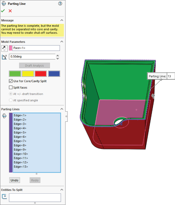
- Notice that SolidWorks has identified a parting line with 13 entities, and that the message at the top of the PropertyManager is yellow (the warning is shown in the following graphic.
- Accept the feature and initiate the Shut Off tool.
- The shut-off may identify both the top and the bottom of the hole as shut-offs, but they will be identified as redundant. You need only one shut-off for this part. The shut-off edge needs to have all red faces on one side and all green faces on the other. So, you should delete the edge that has the same color on both sides. The PropertyManager message should read “The mold is separable into core and cavity” and be in a green field.
- Accept the feature and save your model.
- Master It To finish this simple mold, you need to create a parting surface and split the cavity/core block.
- Initiate the Parting Surface tool. Set the Distance to 4 inches. Your model should look like the following graphic. This is a relatively simple nonplanar parting line, and SolidWorks gets this one correct.

- Initiate the Tooling Split tool and select the big flat face of the parting surface.
- Sketch a square centered on the hole, 6 inches on each side, and exit the sketch.
- Set the block size to 4 inches, and do not use the Interlock option.
- Use F8 to show the Display pane, and expand the Solid Bodies folder and the Parting Surface Bodies folder.
- Make sure to turn off the Draft Analysis mode at this point.
- Designate the top mold as Insert Body and the parting surface as Wireframe, and hide the cavity and core surface bodies as well as the original part.
- Initiate the Parting Surface tool. Set the Distance to 4 inches. Your model should look like the following graphic. This is a relatively simple nonplanar parting line, and SolidWorks gets this one correct.