
Chapter 34
Using SolidWorks Sheet Metal Tools
SolidWorks contains two completely separate methods for working in sheet metal, and they both use regular SolidWorks parts (*.sldprt). In one method, you can use dedicated Sheet Metal features from the start, and in the other method, you build a part using thin features and other generic modeling tools, and then convert it to sheet metal so you can flatten it.
The reason for two methods is that the generic modeling method came first, and then SolidWorks introduced a more powerful set of dedicated Sheet Metal features. You can use these tools together or separately, and either way you get an accurately flattened part at the end. Situations where you might want to use one or the other are covered in this chapter.
Sheet metal tools don't always represent real-world sheet metal manufacturing processes 100 percent accurately, because some shapes that result from bending processes are too complex to easily represent in a CAD model. Sometimes you still have to use your imagination, particularly where bends intersect or overlap.
It is assumed that any cuts to a sheet metal part are sheared normal to the face of the part, unless otherwise specified.
Using the Base Flange Features
The features used in the Base Flange method are easy to grasp conceptually, and they have many individual controls. These are the tools that represent the newer method of building sheet metal parts from dedicated Sheet Metal features. You can edit many of the features by pulling handles, by using spin arrows, or by entering specific numbers or dimensions. Maybe best of all, SolidWorks knows to change the thickness for the entire part at once.
The SolidWorks sheet metal Base Flange method works on a straight brake-press basis. This means that you can place straight bends of a constant radius. The software doesn't behave well when bends intersect, and it doesn't allow bends to cross. SolidWorks doesn't flatten anything where the material deforms or do anything other than a straight bend. The exceptions to this are the lofted bends, swept flanges, and edge flange on a curved edge. You should use these three features sparingly, and you should always verify the results before depending on the flat patterns you get from these features.
You will most often design a part in 3D and then flatten it for manufacturing, but SolidWorks also offers a workflow where you start with a flat pattern and add bend lines to it. Both methods work, but designing in 3D is most effective when you are trying to make a sheet metal part fit together with other parts.
Understanding sheet metal manufacturing processes is very helpful for using SolidWorks sheet metal tools to design functional and manufacturable parts. SolidWorks helps you by not allowing you to create a part that cannot be flattened, but it's still easy enough to model a part that cannot be manufactured or cannot be manufactured economically. You may find it useful to rely on the expertise of either designers with experience or shop personnel to help you learn how to design for sheet metal processes.
You can access the Sheet Metal features by clicking the tool you need in the Sheet Metal tab of the CommandManager or by choosing Insert ➢ Sheet Metal from the menus and selecting the appropriate tool.
Using the Base Flange/Tab Feature
![]() The first feature you add to a sheet metal part is the Base Flange feature. In addition to letting SolidWorks know that the part is a dedicated sheet metal part, the Base Flange/Tab tool has three functions:
The first feature you add to a sheet metal part is the Base Flange feature. In addition to letting SolidWorks know that the part is a dedicated sheet metal part, the Base Flange/Tab tool has three functions:
- By drawing an open contour in the first feature, the Base Flange tool creates a thin feature-like extrusion that includes the rounded corners of the bends.
- By drawing a closed contour in the first feature, the Base Flange tool creates a flat pattern sheet that is shaped like your sketch so you can start.
- When the Base Flange tool is used at any time other than the first feature, it functions as a tab.
Figure 34.1 shows these three functions of the Base Flange/Tab feature.
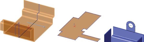
FIGURE 34.1 The three functions of the Base Flange/Tab feature
Notice that the sketch of the part shown in preview in Figure 34.1 has all sharp corners and that the bend radius is automatically added to each corner by the software. SolidWorks automatically adjusts when bend directions are combined to make sure that the inside radius is always the same, regardless of bend direction.
The bends are shown as BaseBend features in the FeatureManager. You can change individual bend radii from the default setting by editing the BaseBend feature, as well as by assigning custom bend allowances on a per-bend basis. You cannot change the bend angle for these particular bends because the angle is controlled through the sketch. However, for other types of bends (such as those created by edge flanges), you can adjust the bend angle through the feature PropertyManager.
If you need to, you can reorder all the bends from a list that you can access from the right mouse button (RMB) menu selection Reorder Bends on the flat pattern. This dialog box is shown in Figure 34.2.

FIGURE 34.2 The Reorder Bends dialog box
The BaseBend features can be suppressed, but the only effect this has is to prevent the associated bend from flattening when the Flat Pattern feature is unsuppressed.
Using the Sheet Metal Feature
![]() The FeatureManager is shown for the Base Flange with all the bends in Figure 34.3. The Sheet-Metal1 feature is automatically added to sheet metal parts as a placeholder for default Sheet Metal settings such as Material Thickness, default Bend Allowance settings, and Auto Relief options, as well as the default Inside Bend Radius.
The FeatureManager is shown for the Base Flange with all the bends in Figure 34.3. The Sheet-Metal1 feature is automatically added to sheet metal parts as a placeholder for default Sheet Metal settings such as Material Thickness, default Bend Allowance settings, and Auto Relief options, as well as the default Inside Bend Radius.
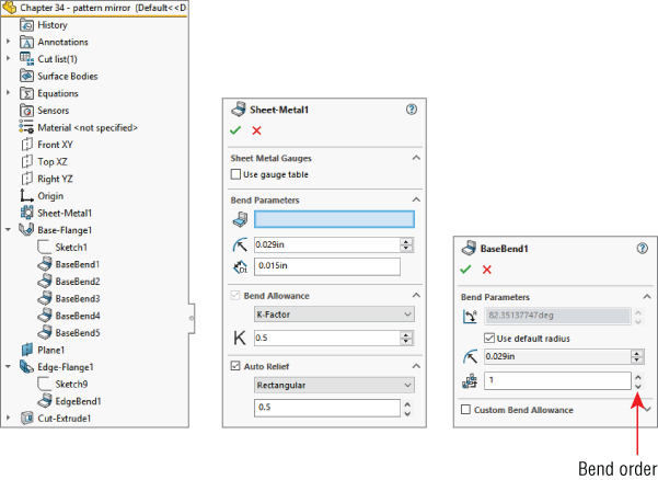
FIGURE 34.3 The FeatureManager after the base flange is added
GAUGE TABLE
Gauge tables are a legacy table type, which is simply an Excel spreadsheet. The data from gauge tables was consolidated with other types of flat pattern calculation into what are now called bend calculation tables, which are described in more detail later in this chapter.
Gauge tables enable you to assign a thickness and available inside-bend radii, which limits the choices that the user has for those settings in the table. Each K-Factor has a separate table, and the choices listed in the table appear in the drop-down lists in the Sheet Metal PropertyManager. Figure 34.4 shows the top few lines of a sample gauge table and a Sheet Metal PropertyManager when a gauge table is used.
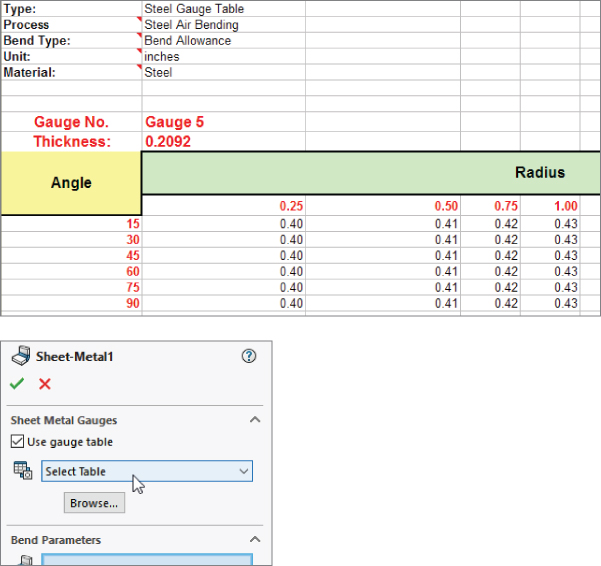
FIGURE 34.4 A sample gauge table and the Sheet Metal PropertyManager
If necessary, you can override the values that are used in the gauge table by using the override options in the thickness, bend radius, and K-Factor fields of the PropertyManager.
The Bend Allowance options (Allowance, Deduction, and K-Factor) are explained in more detail later in this chapter.
BEND RADIUS
This option specifies the default Inside Bend Radius for all bends in the part. You can override the values for individual bends or individual features.
THICKNESS
The Part Thickness is grayed out in the Sheet Metal PropertyManager. You can change the value by double-clicking any face of the model and then double-clicking the thickness dimension displayed in the graphics area. The thickness displays as a blue dimension rather than a black dimension. It's easier to identify if you have dimension names selected, because it's assigned the link value name Thickness and has a red link symbol to the left of the dimension value.
All features in sheet metal parts that use the thickness value use a link value to link all the feature thicknesses. This makes it easy to globally change the thickness of every feature in the entire sheet metal part.
To save these settings to a template file, you can create a Sheet Metal feature, specify the settings, delete the Sheet Metal features, and then save the file to a template with a special name that represents the settings that you used.
BEND ALLOWANCE
You can control the Bend Allowance by using four options:
- Bend Table
- K-Factor
- Bend Allowance
- Bend Deduction
Bend Table
Two general types of bend tables are available: text-based and Excel-based. The first few rows of each type of table are shown in Figure 34.5. Each table can use K-Factor, Bend Allowance, or Bend Deduction.

FIGURE 34.5 Sample text-based and Excel-based bend tables
Sample bend tables can be found in the langenglishSheetmetal Bend Tables subdirectory of the SolidWorks installation directory. Although the values may not be what you need, the syntax and organization are correct. You may want to contact your sheet metal fabrication shop to see what they are using for a table or equations.
K-Factor
When sheet metal is formed from a flat sheet, bending the metal causes it to stretch slightly on the outside part of the bend and to compress slightly on the inside part of the bend. Somewhere across the thickness of the sheet is the neutral plane, where there is no stretching or compression. This neutral plane can be at various places across the thickness, depending on the material, tooling, and process. The ratio of the distance from the inside bend surface to the neutral plane to the thickness is identified as the K-Factor, where 0.5 means halfway, 0 means on the inside face, and 1 means on the outside face. Typically, you can expect values between 0.5 and 0.3.
Bend Allowance and Bend Deduction
Bend Allowance and Bend Deduction are specific length values, not a ratio like the K-Factor. The Bend Allowance is essentially the arc length of the neutral plane through the bend region. The Bend Deduction is the length difference between a sharp corner and the radius corner, as expressed by the formula in Figure 34.6.
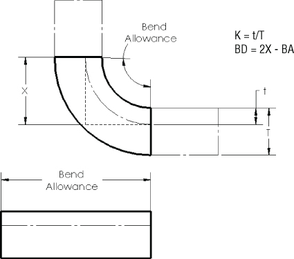
FIGURE 34.6 Calculating the Bend Deduction from the Bend Allowance and K-Factor
The three values are related, as shown in Figure 34.6. The dark rectangle represents the bend area. Material outside of the bend area really doesn't matter, although it's usually shown and used in the generally accepted formulas about bend calculations for sheet metal.
You usually use a ratio t/T (the K-Factor) from a published table or by asking your sheet metal vendor what values they typically use. The values from the tables have been developed experimentally by bending a piece of metal of known length and then measuring the arc length of the inside of the bend and the arc length of the outside of the bend. By comparing these numbers to the original linear length of the bent area, you can find the t value and thus the K value. From the K value, the BA (Bend Allowance) value can be calculated, and from that, the BD (Bend Deduction) value is easy to find.
The specific formulas for finding these numbers aren't as important as an intuitive grasp of what the numbers mean and how they are used, at least in relation to using SolidWorks to model sheet metal parts. The numbers used to fill out bend tables using K, BA, or BD values are typically taken from experimentally developed tables.
Bend Calculation Tables
Bend calculation tables are Excel spreadsheets that enable you to divide bend angles into ranges and assign flat (also referred to as developed) length equations for each range. You can also assign an equation for the K-Factor.
The Excel table must be set up like the example shown in Figure 34.7 in several respects.
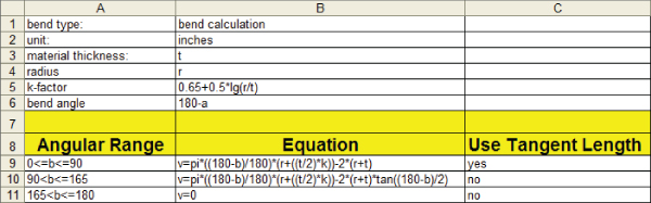
FIGURE 34.7 Setting up the bend calculation table
The declarations in the first several rows must include the following items in the first column (capitalization is not important, but the colon must be as shown). Although the first column may also contain other declarations, it must have at least the ones shown here:
- bend type:
- unit:
- material thickness:
- radius
- k-factor
- bend angle
The available options for Bend Type are Bend Allowance, Bend Deduction, K-Factor, and Bend Calculation.
The available options for Unit are Inch, Millimeter, Meter, and Centimeter (although it looks like plurals are also allowed, such as inches, but abbreviations, such as in, are not).
The Material Thickness can be any variable letter you choose. The Radius can also be any variable letter you choose.
The K-Factor can be an equation or a specific value. In the SolidWorks Web Help, the equation shown as a sample is
The lg in this case is assumed to mean logarithm. I found that the DIN 6935 standard says that the formula for the K-Factor is
This differs from the SolidWorks-provided equation by a /2 term. K is sometimes approximated as ![]() . You should note that K-Factors are usually determined experimentally, and designers who are not intimately familiar with the process details should work with a manufacturing expert to learn the ropes of calculating sheet metal flat patterns.
. You should note that K-Factors are usually determined experimentally, and designers who are not intimately familiar with the process details should work with a manufacturing expert to learn the ropes of calculating sheet metal flat patterns.
The headers shown in Row 8 of the Excel spreadsheet in Figure 34.7 must be spelled as shown without embellishment.
The equations in cells B9 to B11 can use the variables for thickness and radius from the parameters specified in the declarations at the top of the table. It may seem odd, but the equations are just entered as text into the cells of the spreadsheets. They are not active Excel equations. They must be read into SolidWorks and evaluated there, not in Excel. I haven't verified these equations for accuracy. As demonstrated with the K-Factor equation, you should verify the equations yourself or with help before depending on them for production data.
The variable v used on the left side of the equations represents the length of the flattened (developed) bend area. The Web Help (which is the most complete source of information available for this feature as of this writing) refers to a β (beta) variable, which in the equations appears to be replaced with the letter b.
So, you must assume that b stands for bend angle, and the equation for bend angle (180 – a) includes the variable a, which is shown in the Help diagrams as a linear dimension, but which you must assume is the angle through which the sheet metal must bend. So, when a is 45, b is 135, which corresponds to bending the sheet metal 45 degrees, but the bend angle is 135 degrees. Figure 34.8 shows how these variables relate to actual geometry.

FIGURE 34.8 Assigning variables to geometry in bend calculation tables
Notice that the Tangent Length option can apply only when the bend angle is 90 degrees or less. For more than 90 degrees, you must use the Virtual Sharp method.
Also, be aware that the angles here are measured in degrees. In design tables, you have the option to use degrees or radians.
AUTO RELIEF
When a bend doesn't go all the way across a part, some sort of feature is needed at the end of the bend. In real manufacturing processes, the metal may just transition smoothly from the bent area to the flat area; however, in SolidWorks, the software cannot create that smooth transition—or it could, but it would add significantly to sheet metal rebuild times. For this reason, all bends in SolidWorks sheet metal must terminate cleanly, with some sort of a cut, or as they are called here, a relief. SolidWorks allows three kinds of reliefs: Rectangular, Tear, and Obround.
Auto reliefs were formerly called Bend reliefs. You can specify three different Auto Relief options to be applied automatically to bends that end in the middle of material. These options are illustrated in Figure 34.9.
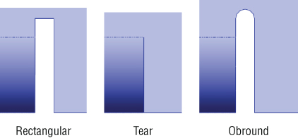
FIGURE 34.9 The three Auto Relief configurations: Rectangular, Tear, and Obround
For the Rectangular and Obround types, you can control the width and the distance past the tangent line of the bend through the Relief Ratio selection box, which is immediately below the Type selection box in the Sheet Metal PropertyManager. This ratio is the width of the relief divided by the part thickness. For the Rectangular relief, a ratio of 0.5 and a thickness of .050 inches means that the relief is 0.025 inches wide and that it goes 0.025 inches deeper into the part beyond the tangent line of the bend. The Obround relief goes slightly deeper because it has a full radius after the distance past the tangent line of the bend, so it essentially goes a total of one full material thickness past the tangent line.
The Tear relief is simply a face-to-face shear of the material with no gap.
Using the Flat Pattern Feature
![]() The Flat Pattern feature is added automatically to the end of the tree when the Base Flange feature is added. This feature is used to flatten the sheet metal part when the feature is unsuppressed. The Flatten toolbar button acts as a toggle to unsuppress or suppress the Flat Pattern feature in the tree. It may be a little confusing, but the Flatten toolbar button and the Flat Pattern feature in the FeatureManager refer to the same functionality. As mentioned earlier, the Flat Pattern feature has a couple of special properties that aren't seen in other features. The first is that it remains at the bottom of the FeatureManager when other Sheet Metal features are added.
The Flat Pattern feature is added automatically to the end of the tree when the Base Flange feature is added. This feature is used to flatten the sheet metal part when the feature is unsuppressed. The Flatten toolbar button acts as a toggle to unsuppress or suppress the Flat Pattern feature in the tree. It may be a little confusing, but the Flatten toolbar button and the Flat Pattern feature in the FeatureManager refer to the same functionality. As mentioned earlier, the Flat Pattern feature has a couple of special properties that aren't seen in other features. The first is that it remains at the bottom of the FeatureManager when other Sheet Metal features are added.
The second property of the Flat Pattern feature is that it's added in the suppressed state. When it's unsuppressed, it flattens out the sheet metal bends.
Notice also that the Flat Pattern PropertyManager allows you to select an edge, axis, or sketch line to denote the grain of the material.
By editing the Flat Pattern feature, you can set a few options. The Flat Pattern PropertyManager is shown in Figure 34.10.

FIGURE 34.10 The Flat Pattern PropertyManager
The Fixed Face parameter determines which face remains stationary when the part is flattened out. Generally, the largest face available is selected automatically, but if you want to specify a different face to remain stationary, you can do that here.
When the Merge Faces option is selected, it causes the flat pattern to form a single face rather than being broken up by the tangent lines around the bends. This does a few things:
- Selecting the face of the flattened part and clicking Convert Entities (found on the Sketch toolbar) makes an outline of the entire flattened part, which is easier to use for certain programming applications.
- The edges around the outside aren't broken up.
- The tangent edges around the bends aren't shown.
The differences between flat patterns with this option selected and unselected are shown in Figure 34.11.
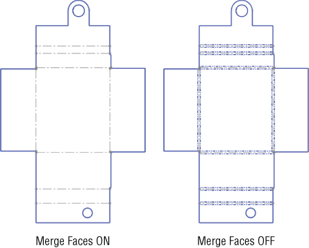
FIGURE 34.11 The Merge Faces option showing on and off
Bend lines are shown in both examples in Figure 34.11.
When you turn on the Simplify Bends option, it simplifies curved edges that are caused by flattening bends to straight lines from arcs or splines. When the option is off, the complex edges remain complex. Simple edges can be cut by standard punches and don't require Computer Numerical Control (CNC)–controlled lasers or abrasive water jets.
The Corner Treatment option controls whether a corner treatment is applied to the flat pattern of a part. The corner treatment is illustrated in Figure 34.12. I created this corner using a model that had a miter flange around the edges of a rectangular sheet.
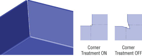
FIGURE 34.12 Using the Corner Treatment setting in the Flat Pattern PropertyManager
Using the Edge Flange Feature
![]() The Edge Flange feature is intended to turn a 90-degree (the default) flange from a selected straight edge in the direction and distance specified using the default thickness for the part. The default workflow for this feature is that you select the tool, select the edge, and then drag the distance, clicking a distance reference such as a vertex at the end of another flange of equal length or typing a distance value manually. You can select multiple edges from a part that don't necessarily need to touch one another. That's all there is to a simple default flange, although several options give you some additional methods for angle, length, and so on. Figure 34.13 shows the Edge Flange PropertyManager, as well as a simple flange.
The Edge Flange feature is intended to turn a 90-degree (the default) flange from a selected straight edge in the direction and distance specified using the default thickness for the part. The default workflow for this feature is that you select the tool, select the edge, and then drag the distance, clicking a distance reference such as a vertex at the end of another flange of equal length or typing a distance value manually. You can select multiple edges from a part that don't necessarily need to touch one another. That's all there is to a simple default flange, although several options give you some additional methods for angle, length, and so on. Figure 34.13 shows the Edge Flange PropertyManager, as well as a simple flange.
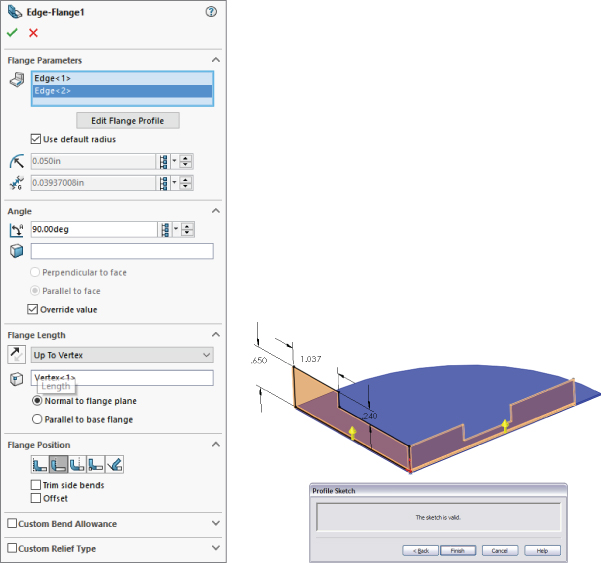
FIGURE 34.13 The Edge Flange PropertyManager and a simple flange
EDIT FLANGE PROFILE
The Edit Flange Profile button in the Edge Flange PropertyManager enables you to edit a sketch to shape the flange in some way other than rectangular or to otherwise edit the shape of the flange. Notice in Figure 34.13 that both of the flanges made by a single Flange feature have been edited. You can do this by selecting the flange for which you want to edit the profile before clicking the Edit Flange Profile button.
You can add holes to the flange profile as nested loops. This enables you to avoid creating additional hole features but doesn't enable you to control the suppression state independently from the Flange feature.
By pulling one of the end lines back from the edge (or past the edge to make it longer), you can make flanges go only part of the way along an edge. This works even though the end lines appear black and fully defined. A situation where the sketch has been edited this way is shown in the image to the right in Figure 34.13.
USE DEFAULT RADIUS
This option enables you to override the default Inside Bend Radius that is set for the entire part for this feature. The bend radii for individual bends within an edge flange that has multiple flanges cannot be set; the only override is at the feature level. If you need individual bends to have different bend radii, you must do this using multiple Edge Flange features.
GAP DISTANCE
The gap distance is illustrated in Figure 34.14. The Gap Distance selection box is active only when you have selected multiple edges in the main selection box for this feature. The gap refers to the space between the inside corners of the perpendicular flanges.
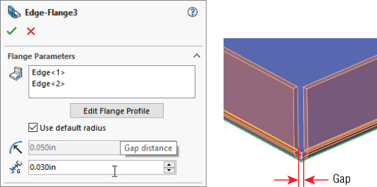
FIGURE 34.14 Specifying the gap distance
ANGLE
Because the edge flange isn't dependent on a sketch for its angle like the base flange is, you can set the angle in the Angle panel of the PropertyManager. The values that this selection box can accept range from any value larger than zero to any value smaller than 180. Of course, each flange has practical limits. In the flange shown in Figure 34.15, the limitation is reached when the bend radius runs into the rectangular notch in the middle of the flange to the right, at about 158 degrees. The angle affects all the flanges that are made with the feature. To create a situation where different flanges have different angles, you must create separate flange features.
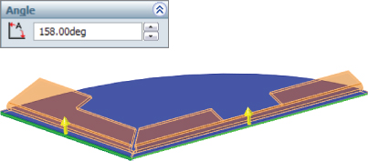
FIGURE 34.15 Establishing the limit of the flange angle
FLANGE LENGTH
As mentioned earlier, if you have edited the Flange profile sketch and a Flange Length dimension is applied in the sketch, then the flange length is taken from that sketch dimension. If this dimension has not been added to the profile sketch, the options for this setting in the PropertyManager Flange Length panel are Blind, Merge, Up To Edge, and Up To Vertex. Using Up To Vertex is a nice way to link the lengths of several flanges.
In the Flange Length panel of the Edge Flange PropertyManager, there are options shown on icons for the start reference of how the Blind length of the flange is measured. These icons should be self-explanatory. They are Outer Virtual Sharp, Inner Virtual Sharp, and Tangent Bend.
FLANGE POSITION
The small icons for Flange Position should be fairly self-explanatory, with the dotted lines indicating the existing end of the material. From left to right, here are the names for these options:
- Material Inside
- Material Outside
- Bend Outside
- Bend From Virtual Sharp (for use when an angle is involved)
- Tangent to Bend
TRIM SIDE BENDS
In situations where a new flange is created next to an existing flange, and a relief must be made in the existing flange to accommodate the new flange, you can select the Trim Side Bends option to trim back the existing flange. Leaving this option unselected simply creates a relief cut, as shown in Figure 34.16. This functionality requires some imagination from the user. A real sheet metal part manufactured like this would have a deformed area in the corner where the bends that are going in different directions overlap. This overlapping bend geometry is too complex for SolidWorks to create automatically, so it offers you a couple of options for how you would like to visually represent the corner. The Flat Pattern is correct, but the formed model requires some imagination.
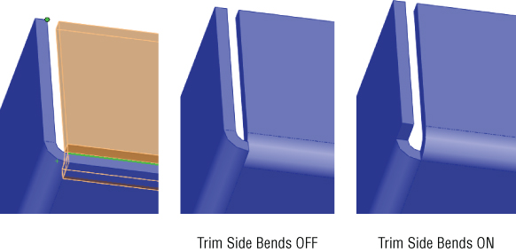
FIGURE 34.16 Using the Trim Side Bends option
CURVED EDGES
Edge flanges can be created on curved edges, but the curved edge must be on a planar face. For example, if the part were the top of a mailbox, then an edge flange could not be put on the curve on the top of the mailbox. The flange would have to be made as a part of the flat end of the mailbox, instead.
Figure 34.17 shows edge flanges used on a part. Notice that reliefs are added to the ends of the bends, although they are not really needed.
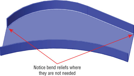
FIGURE 34.17 Curved edge flanges on a part
All the edges that you select to be used with a curved edge flange must be tangent. This means that in Figure 34.17, neither of the edge flanges could have been extended around the ends of the part. You would need to create separate Edge Flange features for those edges.
Because these edge flanges are made in such a way that they are developable surfaces, they can be (and are) flattened in such a way that they don't stretch the material of the flange when the flat is compared to the formed shape. Doubtless, there's some deformation between the two states in the actual forming of this flange, so its manufacturing accuracy may not be completely reliable.
You may also want to examine the Swept Flange feature introduced later in this chapter, as it does some of the same things as curved edge flanges.
Using the Miter Flange Feature
The Miter Flange feature can create picture-frame-like miters around corners of parts; it correctly recognizes the difference between mitered inside corners and mitered outside corners. The PropertyManager and a sample miter flange are shown in Figure 34.18.
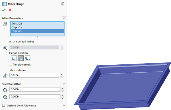
FIGURE 34.18 The Miter Flange PropertyManager and a sample part
A Miter Flange feature starts off with a sketch that's perpendicular to the starting edge of the Miter Flange feature.
Miter Flange sketches can have single lines or multiple lines. They can even have arcs. Still, remember that just because you can make it in SolidWorks doesn't mean the manufacturer can make it. Check with the manufacturer to ensure that the part can be made. Also, you usually will learn something from the experience.
Some of the controls in the Miter Flange PropertyManager should be familiar by now, such as Use Default Radius, Flange Position, Trim Side Bends, and Gap Distance. You have seen these controls before in the Edge Flange PropertyManager.
The Start/End Offset panel enables you to pull a miter flange back from an edge without using a cut. If you need an intermittent flange, you may need to use cuts or multiple Miter Flange features, as shown in Figure 34.19.
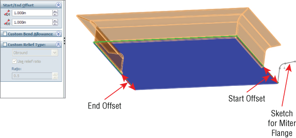
FIGURE 34.19 The Start/End Offset settings for a miter flange
You may find some similarities between functions of the Miter Flange feature and the Swept Flange feature, introduced later in this chapter.
Using the Hem Feature
![]() The Hem feature is used to roll over the edge of a sheet metal part. This feature is often used to smooth over a sharp edge or to add strength to the edge. You can also use it for other purposes, such as to capture a pin for a hinge. SolidWorks offers four different hem styles—Closed, Open, Tear Drop, and Rolled—which are shown as icons on the Hem PropertyManager. The PropertyManager for the Hem feature is shown in Figure 34.20.
The Hem feature is used to roll over the edge of a sheet metal part. This feature is often used to smooth over a sharp edge or to add strength to the edge. You can also use it for other purposes, such as to capture a pin for a hinge. SolidWorks offers four different hem styles—Closed, Open, Tear Drop, and Rolled—which are shown as icons on the Hem PropertyManager. The PropertyManager for the Hem feature is shown in Figure 34.20.

FIGURE 34.20 The Hem PropertyManager and a sample hem
One of the limitations to keep in mind with regard to hems is that SolidWorks cannot fold over a part so the faces touch perfectly line on line. Doing this would cause the two sections of the part to merge into a larger piece, thereby removing the coincident faces. SolidWorks, computers, and mathematics in general don't always handle the number zero very well. In reality, you can often see light through these hems, so a perfectly flush hem may not be as accurate as it seems.
You can edit the profile of the Hem, like an edge flange, to control the length of the edge that's hemmed. To do this, click the Edit Hem Width button below the Edges selection box in the Hem PropertyManager, shown in Figure 34.20.
Using the Jog Feature
![]() The Jog feature puts a pair of opposing bends on a flange so the end of the flange is parallel to, but offset from, the face where the jog started. The Jog PropertyManager and a sample jog are shown in Figure 34.21.
The Jog feature puts a pair of opposing bends on a flange so the end of the flange is parallel to, but offset from, the face where the jog started. The Jog PropertyManager and a sample jog are shown in Figure 34.21.

FIGURE 34.21 The Jog PropertyManager and a sample jog
The Jog feature is created from a single sketch line on the face of a sheet metal part. The geometry to be jogged should have no side bends; it should be a simple tab-like flange (refer to Figure 34.21). The line to create the jog can be drawn at an angle, causing the jog to also be angled.
The three icons on the Jog Offset panel illustrate what dimension is being controlled by that setting.
FIXED FACE
Like most Sheet Metal features, the Jog feature bends faces on the part; when it does so, although it may be obvious to you as the user, it isn't obvious to the software which face should remain stationary and which faces should be moved by the bend. The Fixed Face selection box enables you to select a face, or in this case, a part of a face, that you want to remain stationary as the rest of the faces move. The black dot on the face identifies it as stationary.
JOG OFFSET
You can control the direction of the jog by using the arrow button to the left of the End Condition selection box. You can control the jog distance by selecting the end condition Up To Surface, Up To Vertex, or Offset From Surface. The default setting is Blind, in which you simply enter a distance for the offset, in exactly the same way that end conditions are controlled for features such as extrudes.
FIX PROJECTED LENGTH
One setting that may not be obvious is the Fix Projected Length. This refers to the length of the flange that the jog is altering. In Figure 34.21, you can see that the height of the jogged feature is shorter than the length of the original tab. The jog obviously requires more material than the original, but the Fix Projected Length option is selected, so the height is maintained. If you deselected this option, the finished height of the flange after the jog is added would be shorter, because the material is used by the jog, and additional material is not added. For comparison, the image to the right in Figure 34.21 shows this situation.
JOG POSITION
The Jog Position selection establishes the relationship between the sketched line and the first bend tangent line. The Jog Position icons have tool tips with the following names, from left to right: Bend Centerline, Material Inside, Material Outside, and Bend Outside.
JOG ANGLE
The Jog Angle selection enables you to change the angle of the short perpendicular section of the jog. You can angle it to smooth out the jog (angles of less than 90 degrees) or to curl back on itself (angles of more than 90 degrees). Again, be sure to check your manufacturer's capabilities.
Using the Sketched Bend Feature
![]() Sketched Bend works in some respects like half of a jog. It requires the sketch line and the Fixed Face selection. You define a bend position with the same set of icons that you used in the jog, and you assign a bend angle in the same way.
Sketched Bend works in some respects like half of a jog. It requires the sketch line and the Fixed Face selection. You define a bend position with the same set of icons that you used in the jog, and you assign a bend angle in the same way.
Unlike Jog, the Sketched Bend feature doesn't show you a preview. The Sketched Bend PropertyManager is shown in Figure 34.22.
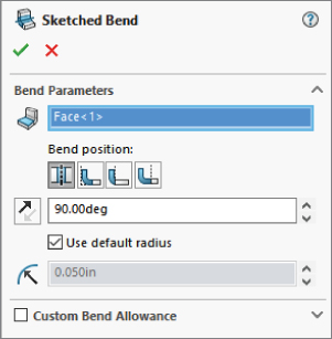
FIGURE 34.22 The Sketched Bend PropertyManager
Using the Closed Corner Feature
![]() The Closed Corner feature extends flanges on the sides to meet with other flanges. It's typically used when corners leave big open gaps in order to create a corner that's more easily welded shut. Figure 34.23 shows a part where angled flanges have been applied. This creates big gaps in the corners. Although a miter flange may have been better, these were created using regular edge flanges.
The Closed Corner feature extends flanges on the sides to meet with other flanges. It's typically used when corners leave big open gaps in order to create a corner that's more easily welded shut. Figure 34.23 shows a part where angled flanges have been applied. This creates big gaps in the corners. Although a miter flange may have been better, these were created using regular edge flanges.

FIGURE 34.23 Applying the Closed Corner feature
FACES TO EXTEND
You must select the thickness face of one of the flanges in order to extend it. Selecting one face automatically selects the matching face from the other flange that you also want to extend. The Corner Type selection icons depict the selected face as red, and the three icons display tool tips: Butt, Overlap, and Underlap.
FACES TO MATCH
The faces selected in the Faces To Match selection box act as an Up To end condition for the faces to extend. SolidWorks 2013 enables you to manually select matching faces in the Faces To Match selection box for those times when the automatic selection does not work.
GAP
The Gap setting enables you to specify how close you want the closed corner to be. Keep in mind that you cannot use the number zero in this field. If you do, SolidWorks will remind you to “Please enter a number greater than or equal to 0.00003937 and less than or equal to 0.86388126.” It's good to know your limits.
OVERLAP/UNDERLAP RATIO
The Overlap/Underlap Ratio setting controls how far across the overlapped face the overlapping flange reaches. Full overlap is a ratio of 1, and a Butt condition is (roughly) a ratio of zero. This ratio is available only when you have specified Overlap or Underlap for the corner type.
OPEN BEND REGION
The Open Bend Region option affects how the finished corner looks in the bend area. If Open Bend Region is selected, then a small gap is created at the end of the bend. If the option is deselected, then SolidWorks fills this area with geometry. Figure 34.24 shows the finished model with this option selected and unselected, as well as the resulting Flat Patterns for each setting.
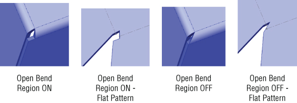
FIGURE 34.24 The Open Bend Region option, both selected and unselected, and the resulting flat patterns
CORNER TRIM AND BREAK CORNER FEATURES
When the Coplanar option is selected, any faces that are coplanar with any selected faces are also selected Corner Trim and Break Corner features. The Corner Trim feature is available only when the sheet metal part is in its flattened state. The Corner Trim PropertyManager also has the Break Corner Options interface built right into it. However, the Break Corner feature is available only when the sheet metal part is in its folded state. Figure 34.25 shows the combined interface. Both functions are included here, and SolidWorks treats them as if they are part of a single function.

FIGURE 34.25 The Corner Trim PropertyManager, including the Break Corner Options panel
![]() When finished, the Corner Trim feature places itself after the Flat Pattern feature in the FeatureManager. It similarly follows the suppress/unsuppress state of the Flat Pattern feature. When the Break Corner feature is used on its own, it's placed before the Flat Pattern feature. With this in mind, it seems best to use Break Corner as a separate feature unless it's being used specifically to alter the flat pattern in a way that cannot be done from the folded state.
When finished, the Corner Trim feature places itself after the Flat Pattern feature in the FeatureManager. It similarly follows the suppress/unsuppress state of the Flat Pattern feature. When the Break Corner feature is used on its own, it's placed before the Flat Pattern feature. With this in mind, it seems best to use Break Corner as a separate feature unless it's being used specifically to alter the flat pattern in a way that cannot be done from the folded state.
![]() Break Corner on its own is primarily used to remove sharp corners using either a chamfer or a rounded corner. This tool is set up to filter edges on the thickness of sheet metal parts, which is useful, because these edges are otherwise difficult to select without lots of zooming. Break Corner can also break interior corners.
Break Corner on its own is primarily used to remove sharp corners using either a chamfer or a rounded corner. This tool is set up to filter edges on the thickness of sheet metal parts, which is useful, because these edges are otherwise difficult to select without lots of zooming. Break Corner can also break interior corners.
One of the main functions of the Corner Trim feature is to apply bend relief geometry to the flat pattern. The three available options are Circular, Square, and Bend Waist. These options are shown in Figure 34.26.

FIGURE 34.26 Applying the Corner Trim Relief options
Using the Corner Relief Feature
![]() SolidWorks also has a Corner Relief feature, which applies corner reliefs in the 3D model. The bend relief in the Corner Trim feature is displayed only in the 2D model.
SolidWorks also has a Corner Relief feature, which applies corner reliefs in the 3D model. The bend relief in the Corner Trim feature is displayed only in the 2D model.
You can manually select corners or allow the software to collect them all for you. You can select from Rectangular, Circular, Obround, Tear, and Constant Width reliefs. Figure 34.27 shows the reliefs previewed on the 3D model, and these carry through to the flat pattern. If you use the Corner Relief feature, you don't need to use the Bend Relief option in the Corner Trim feature.

FIGURE 34.27 Selecting options with the Corner Relief feature
Mirroring and Patterning in Sheet Metal
Most Sheet Metal features can be patterned or mirrored following the same logic as normal SolidWorks parts. Figure 34.28 shows a part with some features mirrored.
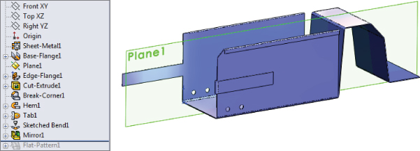
FIGURE 34.28 Mirroring some features on a sheet metal part
MIRRORING SHEET METAL FEATURES
Notice that not all the features are mirrored. In particular, the Corner Break and the Sketched Bend features wouldn't mirror. When you get into a situation where individual features don't mirror, you have two options, just as you do when mirroring a normal SolidWorks part: you can re-create the features on the other side manually or mirror the body rather than the features.
Figure 34.29 shows the same part from Figure 34.28 but modeled by mirroring the body instead of just the features, so all the geometry is symmetrical. You can use this technique along with changing the feature order to make asymmetrical parts when the need arises.

FIGURE 34.29 Mirroring the entire sheet metal body
PATTERNING SHEET METAL FEATURES
Patterning also works for multiple Sheet Metal features. Figure 34.30 shows the patterned tabs with holes and hems. Controlling the bend placement of the first feature changes all the patterned instances. This works nicely, especially because most patterns in sheet metal are less demanding than general patterns.
If you examine the part shown in Figure 34.29 (Chapter 34 - pattern mirror 2.sldprt from the download materials), you'll see that it also contains a mirror feature that mirrors a Closed Corner feature. To me, this is very reasonable pattern/mirror functionality from SolidWorks.
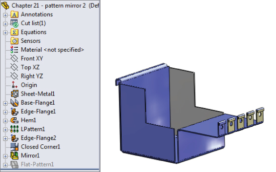
FIGURE 34.30 Patterning multiple features in sheet metal
Forming Tool Feature
![]() SolidWorks has created two methods for applying forming tools. One is to save the forming tool to the Design Library as an
SolidWorks has created two methods for applying forming tools. One is to save the forming tool to the Design Library as an *.sldFTP file type in a generic Library Area folder. The other way is to put a regular *.sldPRT file into a folder specially intended for forming tools. (The words form and forming seem to be used interchangeably, without a discernable difference in what they mean, so I assume they mean the same thing.)
In this chapter, I generally assume to use the method with the special folder, but other than the special folder and the file extensions, I don't see any difference between the two methods for applying forming tools to sheet metal parts in SolidWorks. You should note that the SolidWorks documentation refers to certain forming tools that have been placed in a part before SolidWorks 2012 that may have a lock symbol on them, signifying that they cannot be edited.
Forming tools in SolidWorks enable you to place features that aren't formed on a brake press. These features aren't straight-line bends but rather punched, drawn, formed, lanced, sheared, or otherwise deformed material. One of the important things to understand about forming tools is that they don't stretch the material in the SolidWorks part in the same way that happens in a real-life forming operation. In real life, material is thinned when it is punched, stamped, or drawn. In SolidWorks, the thickness of a sheet metal part remains the same, regardless of what happens to it. For this reason, you need to be careful when using mass properties of sheet metal parts or doing stress analysis of parts that have formed features. You might consider taking your part weight from the flat pattern rather than from the formed sheet metal.
SolidWorks installs with a library of fairly simple forming tools that you can use as a starting point for your own personal customized library. You can also examine some of these tools to see how they create particular effects. You find this library in your Design Library in the Task pane. Some of the more interesting forming tools are the lances and louvers.
CREATING FORMING TOOLS
Current versions of SolidWorks use library features as tools to form another part. For older versions, the forming tools are essentially a part used as a tool to form another part. One flat face of the forming tool part is designated as a stopping face, which is placed flush with the top face of the sheet metal part. You can move and rotate the tool with the Modify Sketch tool, and you can use dimensions or sketch relations to locate it.
To create a forming tool, click the Forming Tool button on the Sheet Metal toolbar. Figure 34.31 shows the PropertyManager interface for this tool.

FIGURE 34.31 The Form Tool PropertyManager and a sample tool with an orientation sketch
The stopping face turns a special color, and so do any faces that are selected in the Faces To Remove selection box. Faces To Remove means that those faces will be cutouts in the sheet metal part.
Another aspect of the forming tool is the orientation sketch. Create the orientation sketch by using Convert Entities on the Stopping Face. The orientation sketch cannot be manually edited; so for forming tools where footprints are symmetrical but other features in the tool are not, you cannot tell from the sketch which direction the forming tool should face.
When creating a forming tool, you must remember to build in generous draft and fillets, and not to build undercuts into the tool. Also keep in mind that when you have a concave fillet face on the tool, the radius becomes smaller by the thickness of the sheet metal; as a result, you must be careful about minimum radius values on forming tools. If a concave face on the tool has a 0.060-inch radius and the tool is applied to a part with a 0.060-inch thickness, the tool will cause an error because it forms a zero-radius fillet, which is not allowed. Errors in applied Forming Tool features cannot be edited or repaired, except by changing forming tool dimensions.
After the forming tool is created, special colors are used for every face on the part. For example, the stopping face is light blue, the faces to remove are red, and all the other faces are yellow. Figure 34.32 shows the small addition made to the FeatureManager when you make a part into a forming tool. This feature didn't exist in older versions of the tool.
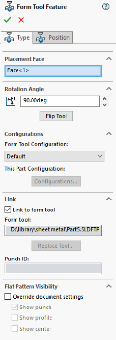
FIGURE 34.32 The FeatureManager of a forming tool part
FORMING TOOL LIBRARY
The folder that the forming tools are placed into in the Design Library must be designated as a Forming Tool folder. To do this, right-click the folder that contains the forming tools and select Forming Tool Folder (a check mark appears next to this option). As I mentioned at the top of this section, this specially designated folder in the Design Library is one of two methods to use forming tools. The other is to place the forming tools in any library folder and use the *.sldFTP extension.
PLACING A FORMING TOOL
To place a forming tool on a sheet metal part (forming tools are allowed to be used only on parts with sheet metal features), you can drag the tool from the library and drop it on the face of the sheet metal part. Forming tools are limited to being used on flat faces.
To position the tool, use the Position tab in the Form Tool Feature PropertyManager, as shown in Figure 34.32. With this tab active, you can create or move sketch points to locate the reference point for the tool. You can also use the properties in the PropertyManager to rotate and even configure the forming tool.
By default, forming tools create external references to the Forming Tool library file. You can turn this off in the PropertyManager. You can also change the tool to reference another file by right-clicking on the tool in the FeatureManager and selecting Replace Form Tool.
SPECIAL TECHNIQUES WITH FORMING TOOLS
One application of forming tools that is asked for frequently is the cross break to stiffen a large, flat sheet metal face. SolidWorks has a cosmetic cross break, which I discuss next. Cross breaks are clearly not something that SolidWorks can do using straight bends, but a forming tool can do it.
You can create the forming tool by lofting a rectangle to a sketch point on a plane slightly offset from the plane of the rectangle. This creates a shallow pyramid shape. Open the part from the material on the website for Chapter 34 called Chapter 34 – Cross Break Sheet Metal.sldprt to examine how this part was made. Figure 34.33 shows the Cross Break forming tool applied to a sheet metal part.
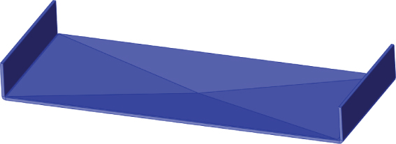
FIGURE 34.33 The Cross Break forming tool applied to a part
Cross Breaks
![]() Using a forming tool to create a cross break is overkill for most situations. You may need to do it if you need to actually show the indented geometry. The Cross Break feature is essentially a cosmetic cross break, and it enables you to specify the radius, angle, and direction used to create the cross break. It doesn't actually change the part geometry at all, but it does add two curve-like display entities.
Using a forming tool to create a cross break is overkill for most situations. You may need to do it if you need to actually show the indented geometry. The Cross Break feature is essentially a cosmetic cross break, and it enables you to specify the radius, angle, and direction used to create the cross break. It doesn't actually change the part geometry at all, but it does add two curve-like display entities.
When you place a Cross Break feature, you have the option to edit the sketch profile that creates the cross. This sketch has two intersecting lines. You cannot add more lines; the feature fails if you have more than two lines in the sketch. (For example, if you wanted to put three breaks across a hexagonal face, the software wouldn't allow this.) The lines don't have to end at a corner, but they do have to end at an edge. If the lines extend past or fall short of an edge, the feature displays a red X error icon, but it still creates the break lines where the sketch lines are.
Figure 34.34 shows the Cross Break PropertyManager and a part to which a cross break was applied. Notice that you can see the break lines through the solid, much like curves or cosmetic threads.

FIGURE 34.34 Creating a cross break
The Cross Break feature shows up in the FeatureManager just like any other feature, not like a cosmetic thread, which is the only other entity in the software that the cross break resembles.
Form Across Bends
A second special technique is a gusset or a form that goes across bends. This can be adapted in many ways, but it's shown here going across two bends. I cannot confirm the practicality of actually manufacturing something like this, but I have seen it done.
The technique used here is to call the single, long flat face of the forming tool the stopping face. The vertical faces on the ends and the fillet faces must be selected in the Faces To Remove selection box. The fillets of the outside of the forming tool also must exactly match the bends of the sheet metal part. You may need to edit this part each time you use it, unless you apply it to parts with bends of the same size and separated by the same distance.
When you place the tool on the sheet metal part, you must place it accurately from side to side to get everything to work out properly. This part is in the same location as the Cross Break file and is called Chapter 34 – Form Across Bends Sheet Metal.sldprt. Figure 34.35 shows the tool and a part to which it has been applied.

FIGURE 34.35 Forming across bends
You may also want to look at the Gusset feature, which is introduced later in this chapter, and is a more conventional way to create gusset geometry.
Using the Lofted Bends Feature
![]() The Lofted Bends feature enables you to create transitions between two profiles. The range of functionality available through the Loft feature isn't available with Lofted Bends; it's limited to two profiles with no end conditions or guide curves. Both profiles also must be open contours in order to allow the sheet metal to unfold.
The Lofted Bends feature enables you to create transitions between two profiles. The range of functionality available through the Loft feature isn't available with Lofted Bends; it's limited to two profiles with no end conditions or guide curves. Both profiles also must be open contours in order to allow the sheet metal to unfold.
The Lofted Bends feature isn't part of the Base Flange method, but it's part of the newer set of sheet metal tools available in SolidWorks. Figure 34.36 shows what is probably the most common application of this feature. The bend lines shown must be established in the PropertyManager when you create or edit the feature. The Bend Lines option is available only if both profiles have the same number of straight lines. For example, if one of the profiles is a circle instead of a rectangle with very large fillets, then the Bend Lines options aren't available in the PropertyManager.

FIGURE 34.36 The Lofted Bends PropertyManager, a sample, and a flat pattern with bend lines
Like the forming tools, you can also use lofted bends in situations for which they were probably not intended. Figure 34.37 shows how lofting between 3D curves can also create shapes that can be flattened in SolidWorks. In this case, a couple of intermediate steps were required to get to the 3D curves, which involve surface features.

FIGURE 34.37 Using 3D curves with the Lofted Bends feature to create flattened complex shapes
The Lofted Bends feature has two methods of working, as shown in Figure 34.37 and Figure 34.38. Bent and Formed on the Manufacturing Method panel are these two choices. A lofted bend with the Bent option will show straight, brake-press-type bends and flat panels of the sheet metal part used to create the shape. A formed bend will show a curved part. Figure 34.38 shows a part using the Bent option on the left and a part using the Formed option on the right. These parts are in the downloads for this chapter. You don't have to use parallel planes or rounded corners in the sketches, but rounded corners make getting the model correct much easier.
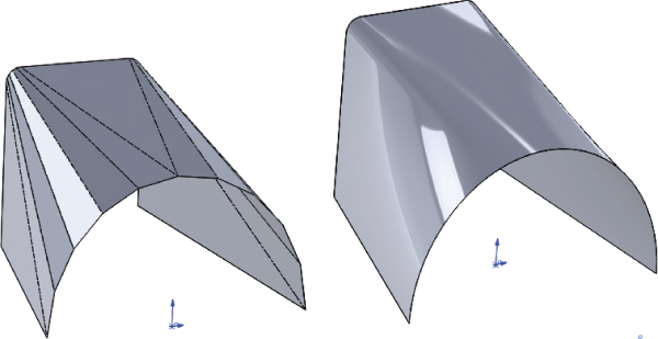
FIGURE 34.38 Lofted bends, bent and formed
Using the Unfold and Fold Features
![]() Unfold is a feature that unfolds selected bends temporarily. It's typically used in conjunction with a Fold feature to refold the bends. This combination is used to apply a feature that must be applied to the flat pattern—for example, a hole that spans across a bend.
Unfold is a feature that unfolds selected bends temporarily. It's typically used in conjunction with a Fold feature to refold the bends. This combination is used to apply a feature that must be applied to the flat pattern—for example, a hole that spans across a bend.
![]() Figure 34.39 shows the FeatureManager of a part where this combination has been applied, as well as the part itself, showing the bend across a hole, and the PropertyManager, which is the same for both features.
Figure 34.39 shows the FeatureManager of a part where this combination has been applied, as well as the part itself, showing the bend across a hole, and the PropertyManager, which is the same for both features.
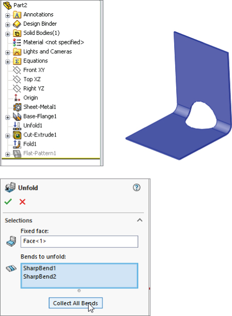
FIGURE 34.39 Applying the Unfold and Fold features
Both the Unfold and Fold features make it easy to select the bends without zooming in, even for small bends. A filter is placed on the cursor when the command is active, which allows only bends to be selected. The Collect All Bends option also becomes available. This feature also requires that you select a stationary face to hold still while the rest of the model moves during the unfolding and folding process.
Using the Swept Flange Feature
![]() The Swept Flange feature is similar to the Miter Flange, with the main difference being that Swept Flange is used to create a new sheet metal part, while the Miter Flange is used in an existing sheet metal part. Also, the Miter Flange feature will add reliefs along the way, and the Swept Flange feature will not. This implies that the two features will probably be used in different types of manufacturing processes; Miter Flange looks more like a straight, brake-press-type operation, and Swept Flange has elements of a die rolling process, stamping, or possibly progressive die.
The Swept Flange feature is similar to the Miter Flange, with the main difference being that Swept Flange is used to create a new sheet metal part, while the Miter Flange is used in an existing sheet metal part. Also, the Miter Flange feature will add reliefs along the way, and the Swept Flange feature will not. This implies that the two features will probably be used in different types of manufacturing processes; Miter Flange looks more like a straight, brake-press-type operation, and Swept Flange has elements of a die rolling process, stamping, or possibly progressive die.
Like any sweep, the Swept Flange feature requires a path (curve, sketch, edges, Selection Manager selection) and a profile sketch to drive along that path. Both selections must be open profiles, since the part is made from flat (probably roll) stock, not tube.
Figure 34.40 shows the sketches used to create the example and the PropertyManager of the Swept Flange feature, as well as the resulting FeatureManager. This feature can be flattened by the software—but again, remember, you have to apply your knowledge of the limits of material processing to know what is possible to manufacture and what is not.
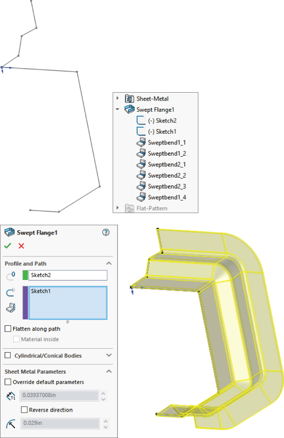
FIGURE 34.40 Creating a swept flange
A swept flange is typically flattened as if it were formed from a roll of material, like a rain gutter on the side of a house (see Figure 38.41). This means the profile is flattened, and the path is straightened out as well, making a rectangular blank. When the Flatten Along Path option is checked, the profile is flattened, but the path is not straightened, giving a blank roughly the shape of the path. The Material Inside option will change the neutral plane and may fail on one side or another, according to self-intersection issues with the flattening (if it doesn't work when it's on, try turning it off).
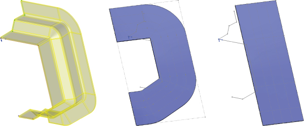
FIGURE 34.41 Flattening a swept flange
Using the Gusset Feature
![]() The Gusset feature enables you to place a stiffening gusset on your part quickly and easily. On an existing sheet metal part, initiate the Gusset feature and select a location on a bend. The default gusset is 45 degrees and rounded, but you can create flat-top gussets, add side draft, change the angle and width, as well as fillet dimensions.
The Gusset feature enables you to place a stiffening gusset on your part quickly and easily. On an existing sheet metal part, initiate the Gusset feature and select a location on a bend. The default gusset is 45 degrees and rounded, but you can create flat-top gussets, add side draft, change the angle and width, as well as fillet dimensions.
Figure 34.42 shows the Sheet Metal Gusset PropertyManager (in two parts), along with a preview of the feature. Since this is sheet metal, remember that the material is a constant thickness (although in reality there will be some variation of thickness when you deform a part like this).
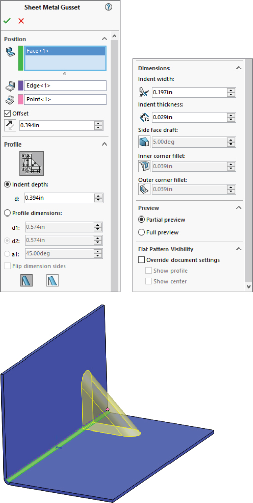
FIGURE 34.42 Creating a gusset on a bend
If you need a shape other than the one provided by the Gusset feature, you may have to resort to the technique demonstrated in the earlier section “Form Across Bends.”
Using the Tab and Slot Feature
![]() The Tab and Slot feature is meant to create geometry to help physically assemble your product. It can be used in a single part, a multibody part, or an assembly. This is a Sheet Metal feature, but it can also be used in weldments and general parts for woodworking joints and other processes or materials.
The Tab and Slot feature is meant to create geometry to help physically assemble your product. It can be used in a single part, a multibody part, or an assembly. This is a Sheet Metal feature, but it can also be used in weldments and general parts for woodworking joints and other processes or materials.
Let's start with an example where a single part is formed that uses a tab and slot to give it more rigidity. The first time you work through this feature, the PropertyManager may look intimidating, but with some practice (and after reading the tool tips), you will become familiar with the workflow.
- Select edge on which the tab(s) will be created.
- Select the face to which the tab will extend.
- Select two points that will serve as the limits of the tab area. By default, these are the ends of the first edge you selected. If you want something more specific, it might be a good idea to sketch it in and use the end points of the sketch to limit the tab.
The Offset panel refers to the width of the tab, and the offset will be measured from the points you specified in the previous step.
Spacing enables you have a pattern of tabs or just a single tab.
Length enables you to specify how long or how long in relation to the face you selected in the second step that tab sho0uld be. For example, if the tab is to be welded, it should be flush with the surface, but if it is to be peened, bent with hand tools, or crushed into place, it should protrude out beyond the surface.
The Slot panel enables you to specify how much bigger the slot is than the tab, for ease of assembly.
You can create multiple sets of tabs and slots by using the New Group feature to start a second set.
Figure 34.43 shows a strip of sheet metal formed into a box for extra rigidity, using three tabs and slots to join together the box.

FIGURE 34.43 Creating joining tabs and slots to form a box
The sample part for this screen capture is named Chapter 34 - Tab and Slot.slprt and included with the download materials for this chapter.
Making Sheet Metal Parts from Generic Models
SolidWorks can also convert generic constant-thickness models into sheet metal parts that flatten and on which any of the dedicated Sheet Metal features can be used. You can make models from Thin Feature extrudes or regular extrudes with Shell features and then use the Insert Bends feature to make them sheet metal parts. The structure of parts created with the Insert Bends feature is somewhat different. Figure 34.44 shows a comparison of the two methods' FeatureManagers for simple parts.
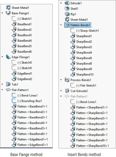
FIGURE 34.44 Comparing the default features for the Base Flange and Insert Bends features
The most notable difference is that the Insert Bends part starts off with non–Sheet Metal features. The Rip feature also stands out, but the Rip feature is not exclusive to sheet metal. Although you can use Rip on any model, it's found only on the Sheet Metal toolbar.
The Sheet Metal feature is found in both the Base Flange and Insert Bends methods and has the same PropertyManager function in both methods.
The new features in the Insert Bends method are the Flatten Bends and Process Bends features. The way the Insert Bends method works is that the model that's built with the sharp-cornered non–Sheet Metal feature is flattened by the Flatten Bends feature. The model is then reconstructed with bends by the Process Bends feature.
The main rule that SolidWorks enforces on sheet metal models regardless of how they came to be sheet metal is that the parts should have a consistent wall thickness. When all the geometry is made from the beginning as a sheet metal part (using the Base Flange method), there's never a problem with this. However, when the part is modeled from thin features, cuts, shells, and so on, there's no telling what may happen to the model.
If you perform an Insert Bends operation on a model that doesn't have a consistent wall thickness, then the Flatten Bends and Process Bends features fail. If a thickness face isn't perpendicular to the main face of the part, then the software simply forces the situation, making the face perpendicular to the main face.
Using the Normal Cut Feature
![]() If a Cut feature is placed before the Sheet Metal feature, then as far as SolidWorks is concerned, the part is not a sheet metal part. However, if the Cut feature is created after the Sheet Metal feature, the model must follow a different set of rules. The “normal shear” mentioned previously is one of those rules. In Figure 34.45, the sketch for a cut is on a plane that isn't perpendicular to the face into which the cut is being made. Under a normal modeling situation, the cut would just go through the part at an angle. However, in SolidWorks sheet metal, an option is added to the PropertyManager for the cut. This is the Normal Cut option, and it's selected by default. You could be modeling and never even notice this option, but it's important because it affects the geometrical results of the feature. It is also a stand-alone feature that can be applied to the model after abnormal cuts have been made.
If a Cut feature is placed before the Sheet Metal feature, then as far as SolidWorks is concerned, the part is not a sheet metal part. However, if the Cut feature is created after the Sheet Metal feature, the model must follow a different set of rules. The “normal shear” mentioned previously is one of those rules. In Figure 34.45, the sketch for a cut is on a plane that isn't perpendicular to the face into which the cut is being made. Under a normal modeling situation, the cut would just go through the part at an angle. However, in SolidWorks sheet metal, an option is added to the PropertyManager for the cut. This is the Normal Cut option, and it's selected by default. You could be modeling and never even notice this option, but it's important because it affects the geometrical results of the feature. It is also a stand-alone feature that can be applied to the model after abnormal cuts have been made.
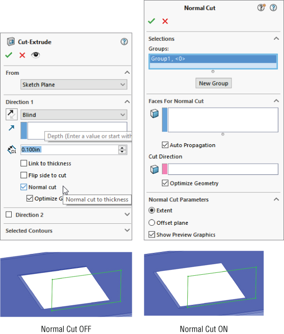
FIGURE 34.45 Using the Normal Cut option
As shown in Figure 34.45, when the Normal Cut option is selected, the thickness faces of the cut are turned perpendicular (or normal) to the face of the sheet metal. This is also important because if the angle between the angled face and the sketch changes, the geometry of the cutout can also change. This setting becomes more important as the material becomes thicker and as the angle between the sketch and the sheet metal face becomes shallower.
SolidWorks allows you to have angled faces on side edges and maintains the angle when it flattens the part. A cut that doesn't use the Normal Cut option and creates faces that aren't perpendicular to the main face of the part doesn't cause the Flat Pattern feature to fail.
Using the Rip Feature
![]() When someone is building a sheet metal part from a generic model, a common technique that is used to achieve consistent wall thicknesses is to build the outer shape as a solid and then shell the part. The only problem with this method is that it leaves corners joined in a way that cannot be flattened. You can solve this problem by using the Rip feature. Rip breaks out the corner in one or both directions in such a way that it can be unfolded. Bend reliefs are later added automatically by the Process Bends feature.
When someone is building a sheet metal part from a generic model, a common technique that is used to achieve consistent wall thicknesses is to build the outer shape as a solid and then shell the part. The only problem with this method is that it leaves corners joined in a way that cannot be flattened. You can solve this problem by using the Rip feature. Rip breaks out the corner in one or both directions in such a way that it can be unfolded. Bend reliefs are later added automatically by the Process Bends feature.
Figure 34.46 shows the Rip PropertyManager and the results of using this feature. The model was created to look like a Miter Flange part.

FIGURE 34.46 Using the Rip feature
Notice also in Figure 34.46 that after the Rip, the edges of the material are still sheared at an angle. Because the top of the part was shelled, the thickness of the part is not normal to the main face of the sheet metal. You can fix this by using the Flatten Bends feature, which lays the entire part out flat, calculates the bend areas, and corrects any discrepancies at the edges of the part.
Using the Sheet Metal Feature
![]() The Sheet Metal feature used in the Insert Bends method is very similar to the one used in the Base Flange method. However, two main differences exist: Insert Bends Sheet Metal requires the user to select a fixed face, and Base Flange Sheet Metal allows the use of gauge tables. Both features function as placeholders and otherwise contain the same information, use the same name and icon, and are inserted automatically when a different feature is created.
The Sheet Metal feature used in the Insert Bends method is very similar to the one used in the Base Flange method. However, two main differences exist: Insert Bends Sheet Metal requires the user to select a fixed face, and Base Flange Sheet Metal allows the use of gauge tables. Both features function as placeholders and otherwise contain the same information, use the same name and icon, and are inserted automatically when a different feature is created.
Using the Flatten Bends Feature
![]() The Flatten Bends feature is added automatically by the Insert Bends tool. As mentioned earlier, it takes the model with sharp corners and lays it flat, adjusting the material in the bend area and normalizing the thickness faces around the flat pattern. The Merge Faces option is available in the Flat Pattern feature in the Insert Bends method; therefore, the flat pattern created by the Flatten Bends feature always has edges created by the tangent lines of the bends.
The Flatten Bends feature is added automatically by the Insert Bends tool. As mentioned earlier, it takes the model with sharp corners and lays it flat, adjusting the material in the bend area and normalizing the thickness faces around the flat pattern. The Merge Faces option is available in the Flat Pattern feature in the Insert Bends method; therefore, the flat pattern created by the Flatten Bends feature always has edges created by the tangent lines of the bends.
Notice in Figure 34.47 that the Flatten Bends feature has a sketch and several Sharp Bend features under it. The Sharp Sketch is simply an account of the bend lines, and you cannot edit it manually. The Sharp Bend features can be suppressed, in which case they aren't reformed in the Process Bends feature. You can also edit Sharp Bend features to change the default radius, bend allowance, and relief type.
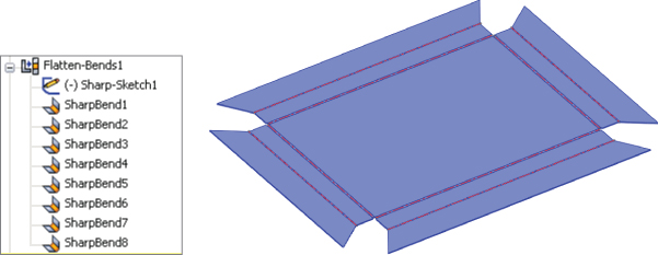
FIGURE 34.47 Using the Flatten Bends feature
Using the Process Bends Feature
![]() The Process Bends feature takes all the flat pattern information, the bend information, and entities in the flat sketch and rebuilds the model with the formed bends. The flat sketch under the Process Bends feature is the Insert Bends method version of a sketched bend. You can add sketch lines here to bend panels of the part. After you add lines to this sketch, exiting the sketch will cause the part to be created with a default 90-degree bend corresponding to the line. Of course, all the Sketched Bend rules exist, such as that the line has to extend at least up to the edges of the part, the lines cannot extend across multiple faces, and construction lines are ignored.
The Process Bends feature takes all the flat pattern information, the bend information, and entities in the flat sketch and rebuilds the model with the formed bends. The flat sketch under the Process Bends feature is the Insert Bends method version of a sketched bend. You can add sketch lines here to bend panels of the part. After you add lines to this sketch, exiting the sketch will cause the part to be created with a default 90-degree bend corresponding to the line. Of course, all the Sketched Bend rules exist, such as that the line has to extend at least up to the edges of the part, the lines cannot extend across multiple faces, and construction lines are ignored.
For every bend created by a sketch line in the Process Bends Flat Sketch feature, a Flat Bend feature is added to the list under Process Bends. You can control the angle and radius of each of these flat bends by editing the Flat Bend feature. This is all illustrated in Figure 34.48.

FIGURE 34.48 Using the Process Bends feature
Using the No Bends Feature
![]() With a single button click, you can use the No Bends tool on the Sheet Metal toolbar to roll back the model before the Flatten Bends feature in the tree. This is used primarily to add new geometry that is turned into bends through the Flatten and Process Bends features.
With a single button click, you can use the No Bends tool on the Sheet Metal toolbar to roll back the model before the Flatten Bends feature in the tree. This is used primarily to add new geometry that is turned into bends through the Flatten and Process Bends features.
Using the Flat Pattern Feature
![]() The Insert Bends method uses the Flat Pattern feature as well as the Base Flange method. However, it wasn't part of the original scheme and was added at some point after the new tools had proved their value. This enables you to utilize the new features as well, as discussed later in this chapter in the section on Mixing Methods, page 988.
The Insert Bends method uses the Flat Pattern feature as well as the Base Flange method. However, it wasn't part of the original scheme and was added at some point after the new tools had proved their value. This enables you to utilize the new features as well, as discussed later in this chapter in the section on Mixing Methods, page 988.
Using the Convert To Sheet Metal Feature
![]() The Convert To Sheet Metal feature can use either SolidWorks native data or imported data. It can also use solids as well as surfaces. The model can be shelled or not shelled and have filleted edges or not. This feature enables you to identify which edges will become bends and automatically identifies the edges to rip. See Figure 34.49.
The Convert To Sheet Metal feature can use either SolidWorks native data or imported data. It can also use solids as well as surfaces. The model can be shelled or not shelled and have filleted edges or not. This feature enables you to identify which edges will become bends and automatically identifies the edges to rip. See Figure 34.49.

FIGURE 34.49 Using the Convert To Sheet Metal feature
This tool is very useful for imported geometry and for parts with tricky shapes. Although the PropertyManager interface looks complex, it's fairly straightforward to use. Your first selection in the top Fixed Entity box should be a stable face, preferably an outer face on the bottom or the top. Inner faces generally don't work.
Note that you can reverse the thickness of the sheet metal, so the solid that you start with can be treated as the volume inside the sheet metal enclosure, or the outer faces of the initial solid turn out to be the inner faces of the sheet metal part. Use the Reverse Thickness option to accomplish this.
Selecting Bend Edges is the next step, with the implication that any edge that isn't a bend will be ripped. Also note that three bend edges cannot intersect at a point, and one bend edge cannot intersect at the middle of another edge.
The default Bend Radius, Thickness, and Auto Relief options are set the same way as in other Sheet Metal functions.
Using Other Methods
The sheet metal tools have been available in SolidWorks for quite some time and have had some time to mature and for users to become well acquainted with them and develop effective techniques using them.
Working with Imported Geometry
Working with imported geometry starts at the point where you use the Rip feature. Although imported geometry can be geometrically manipulated to some extent in SolidWorks, this is beyond the scope of this chapter. The need for a model with walls of constant thickness still exists, even if the imported model has filleted edges showing bend geometry already in the model.
FeatureWorks can be used to recognize Sheet Metal features or to fully or partially deconstruct the model by removing bend faces as fillets. Although FeatureWorks is not covered in this book, the technique may be useful when editing imported parts with overall prismatic geometry that is common to sheet metal parts.
When a sheet metal part is imported, whether it meets the requirements immediately or must be edited in one way or another to make a sheet metal part of it, you can simply use the Insert Bends feature or even the Convert To Sheet Metal feature.
Making Rolled Conical Parts
One of the reasons for maintaining the legacy Insert Bends method is to have a way of creating rolled conical parts. You can create cylindrical sheet metal parts by drawing an arc that almost closes to an entire circle and creating a base flange from it. However, you can also use swept flanges or lofted bends for these types of models.
With the Insert Bends method, a revolved thin feature does the job nicely. You simply revolve a straight line at an angle to the centerline, so the straight line doesn't touch or cross the centerline; the revolve cannot go around the full 360 degrees, because there must be a gap. Sheet metal parts aren't created by stretching the material (except for forming tools).
When creating a rolled sheet metal part, you cannot select a flat face to remain fixed when the part is flattened. Instead, you can use a straight edge along the revolve gap, as shown in Figure 34.50.

FIGURE 34.50 Selecting a straight edge for a conical part
Mixing Methods
If you use the Insert Bend tool on a part, you can still use the more advanced tools available through the Base Flange method, unless it's a cylindrical or conical part. A Flat Pattern feature is added to the bottom of most Sheet Metal feature trees, and the presence of this feature is what signifies that the current part has now become a sheet metal part to the Base Flange features.
However, I recommend that you avoid mixing the different techniques to flatten parts—for example, suppressing bends under Flatten and Process bends, as well as using the flat pattern.
Using Multibody Techniques with Sheet Metal
You can use multibody techniques with sheet metal models. For many of the same reasons you might want to make any other kind of model using multibody techniques, you may also want to make sheet metal parts using similar techniques. When you create parts using multibody techniques, you can have multiple Base Flange features. With those multiple Base Flange features, you also get multiple Flat Pattern features. Also, you can use the Split feature to create multiple sheet metal bodies. The rules laid out for multibody parts are generally also going to apply for multibody sheet metal parts and have several implications for limitations of sheet metal parts, such as the following:
- If you have multiple bent bodies, you can show only one body flattened at a time.
- By merging sheet metal bodies, you eliminate both Flat Pattern features of the old bodies and create a brand new Flat Pattern feature for the new body.
These commands can create new bodies in sheet metal parts:
- Convert To Sheet Metal
- Lofted Bend
- Insert Bends
- Base Flange
- Insert Part
- Split
These commands can merge bodies in sheet metal parts:
- Edge Flange
- Combine
The Mirror function enables you to mirror bodies, but the new bodies must to be merged manually with the existing body.
A multibody sheet metal part has a Cut List folder, which acts like a Solid Bodies folder and lists each sheet metal body. Each cut-list item lists the sheet metal body and, under that, the features associated with each body. The part also has a Sheet Metal folder with a Sheet Metal feature for each body. The Sheet Metal features for each body hold the defaults for each body, such as thickness and bend radius. The Flat Pattern folder includes a Flat Pattern feature for each body. Each body can be flattened individually, but not at the same time.
Using Insert Part
Using the Insert Part feature inserts an existing part as a new body inside a sheet metal part, but even if the inserted part had been a sheet metal part initially, it wouldn't show up as sheet metal after being inserted in the other part.
You can join the inserted part to the local sheet metal body by using the Combine feature, but not by using the Merge option in an edge flange as you can to merge two bodies modeled within a single part. When the Combine feature is used, any sharp intersection between the parts is left sharp and won't flatten unless you use the Insert Bends feature to convert the sharp into a bend. This is an odd twist on combining the old (Insert Bends) method with the new (Base Flange) method.
Using Multiple Base Flanges
Another method to get multiple bodies inside a sheet metal part is to start from disjoint Base Flange features. You cannot have multiple open profiles in your first feature, but you can have multiple Base Flange features. From there, you can build flanges toward one another until flanges touch. Figure 34.51 illustrates a situation where a disjoint flange created by a Base Flange feature is connected to the main part using an Edge Flange feature with the Up To Edge And Merge option selected in the Flange Length section.

FIGURE 34.51 Using an edge flange to connect disjoint bodies in a sheet metal part
Tutorial: Working with the Insert Bends Method for Sheet Metal Parts
The Insert Bends method has been relegated to duty mainly for specialty functions. To gain an understanding of how this method works, follow these steps:
- Create a new blank part.
- On the Top plane, open a sketch and sketch a rectangle centered on the origin 12 inches in the horizontal direction and 8 inches in the vertical direction.
- Extrude the rectangle 1 inch with 45 degrees of draft, Draft Outward, in Direction 1, and extrude 1 inch with no draft in Direction 2. The two directions should be opposite from one another.
- Shell out the part to .050 inches, selecting the large face on the side where the draft has been applied. The part should now look like Figure 34.52.

FIGURE 34.52 The part as of step 4
- Use the Rip feature to rip out the four corners. Allow the Rip to rip all corners in both directions. The part should look like Figure 34.53.
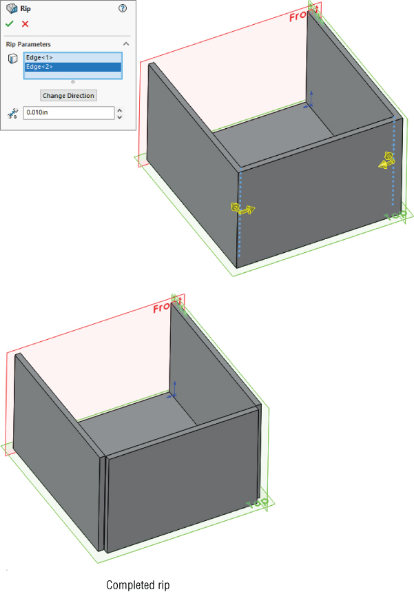
FIGURE 34.53 Ripping the corners
- Create an Insert Bends feature, accepting the default values and picking the middle of the base of the part for the fixed face.
- Draw a rectangle on one of the vertical faces of the part, as shown in Figure 34.54.

FIGURE 34.54 Adding a sketch for the cut
- Use the sketch to create a Through All cut in one direction. Notice that the Normal Cut option is on by default. Examine the finished cut closely; notice that it's different from the default type of cut because it's not made in a direction normal to the sketch but rather in a direction normal to the face of the part. Details of this are shown in Figure 34.55.
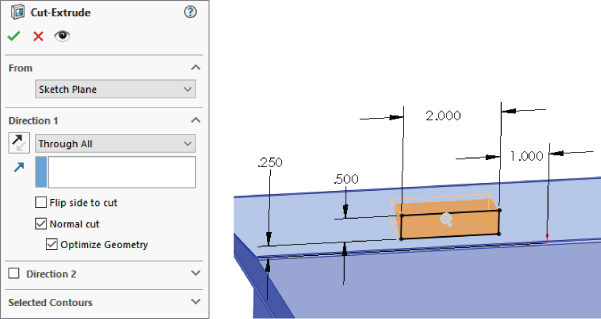
FIGURE 34.55 Using the Normal Cut option
- Click the Flatten button on the Sheet Metal toolbar. Notice that the Flat Pattern feature becomes unsuppressed and that the Bend Lines sketch under it is shown. This works just as it did in the Base Flange method. The finished part is shown in Figure 34.56.
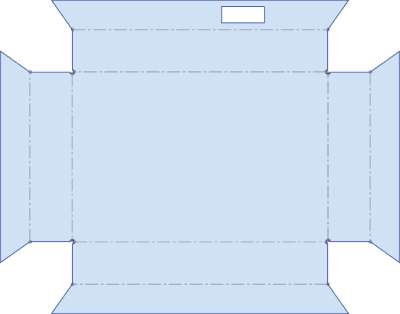
FIGURE 34.56 The finished part with the Flat Pattern feature unsuppressed
Tutorial: Using the Base Flange Sheet Metal Method
SolidWorks Base Flange method for sheet metal is fun and easy to use, as you'll see in this tutorial:
- Open a new part using a special Sheet Metal template if one is available.
- On the Top plane, draw a rectangle centered on the origin, 14 inches in X by 12 inches in Y (or Z).
- Initiate the Base Flange tool, set the thickness to 0.029 inches, and change the K-Factor to .43. Notice that the default Inside Bend Radius is not shown. This setting is made in the Sheet Metal feature that's placed before the Base Flange feature in the FeatureManager.
- After the base flange has been created, edit the Sheet Metal feature and change the default bend radius to 0.050 inches.
- Click one of the 14-inch edges and then select the Line tool from the Sketch toolbar. This is a shortcut to creating a plane perpendicular to the end of the edge and opening a new sketch on the plane. This is useful in other situations in addition to working with sheet metal. Draw a sketch similar to the one that’s shown in Figure 34.57. The arc overrides the default Inside Bend Radius setting and directly controls that particular bend.

FIGURE 34.57 The sketch to start a miter flange
- With the sketch still active, click the Miter Flange button on the Sheet Metal toolbar. Use the settings shown in the image to the right in Figure 34.58. Select three edges as shown. Remember to select the edges on the same side of the base flange. In particular, notice the Start/End Offset settings. Click OK when you are satisfied with the settings.
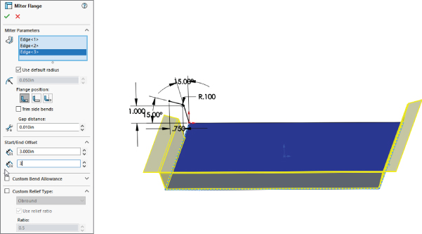
FIGURE 34.58 Specifying the Miter Flange settings
- Select the remaining edge that isn't touched by the miter flange, and click the Edge Flange tool on the Sheet Metal toolbar. Click the top point of one end of the miter flange to establish the flange length using the Up To Vertex end condition.
- Click the Edit Flange Profile button in the PropertyManager, and manually pull the sketch back from the ends of the flange. Add dimensions to make the flange 3 inches from the corner on the left side, and 5 inches from the corner on the right side, as shown in Figure 34.59; otherwise, use the default settings for the flange. Click OK to accept the feature when you are satisfied with the settings.
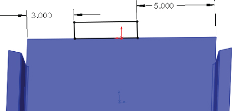
FIGURE 34.59 Creating an edge flange
- Select the inside edge of the top of the edge flange that you have just created and initiate a Hem feature. Use the settings Material Inside, Closed Hem, with a length of 0.25 inches, and make the material go toward the inside of the box. The settings and preview of the feature are shown in Figure 34.60.

FIGURE 34.60 Creating a hem
- Create a second edge flange the same height as the first, just to the right of the first flange. Edit the Flange profile, and pull the new flange away from the existing flange. Add a dimension to make the new flange 2 inches wide. Click OK when you are satisfied with the settings.
- Open a sketch on the inside face of the new edge flange and draw a line across the flange 0.75 inches from the end.
- Create a Jog feature with the settings shown in Figure 34.61. Make sure to set a custom bend radius by deselecting the Use Default Radius option and entering 0.025 inches. If you don't set the custom radius, you may get a warning that the jog distance is less than a minimum jog value. When you’re selecting the fixed face, be careful to select the side of the line with the largest area or the face you want to remain where it is while the rest of the part bends and moves around it.

FIGURE 34.61 Creating a jog
- From the website, in the download materials for Chapter 34, find the part named
Chapter 34 – Cross Break.sldprt. Copy this file to a folder in the library that you have established outside of your SolidWorks installation folder, called Forming Tools. - Make sure this folder appears in the Design Library. You may have to press F5 or click the Refresh button at the top of the Task pane. When the folder appears, right-click the folder and select the check mark next to Forming Tools folder.
- When the file has been copied and the folder has been assigned as a Forming Tool folder, drag the
Chapter 34 – Cross Breakpart from the folder and onto the big flat face of the sheet metal part. It will be put into a sketch that looks like Figure 34.62.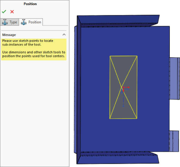
FIGURE 34.62 Placing a forming tool
- After you have dropped the feature into the sketch, drag the origin of the sketch onto the origin of the part and click Finish. Notice that the cross break is in the middle of the part, but it's too small.
- Double-click the new feature in the FeatureManager; a set of dimensions will appear on the screen. Change the 4-inch dimension to 13.9 inches and the 6-inch dimension to 11.9 inches. The cross break should look like Figure 34.63.
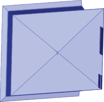
FIGURE 34.63 Resizing the cross break to 13.9 inches
- Create a new configuration named Flat. In this configuration, suppress the forming tool that you just placed, and unsuppress the Flat Pattern feature at the bottom of the tree.
The Bottom Line
SolidWorks offers a broad range of sheet metal tools to tackle most of your modeling situations. Some of the tools still require a little imagination to visualize real-world results because the complex shapes created in the real world where bends intersect are problems for such highly automated software. The tools are able to deal with imported or generically modeled geometry as well as parts created using the dedicated sheet metal tools.
- Master It There are three basic methods for working with sheet metal in SolidWorks: Base Flange, Insert Bends, and Convert Entities. We'll have one exercise for each method.
Follow these steps to build a basic Base Flange type part:
- Create a sketch like the one shown here.
- Use the Base Flange tool on the Sheet Metal toolbar to extrude the sketch midplane 4 inches, with a thickness of 0.025 inch.
- Add a flange to one of the open sides that matches the height of the tallest flange (use Up To Vertex). The defaults are an Inside Bend Radius of 0.029 inches, an angle of 90 degrees, and the flange position set to Inside. Turn on Custom Relief and use the Tear type.

- Put a Sheet Metal Gusset feature in the middle of the newly created bend. Here are the settings:
- Offset = 1.5″
- Indent Depth = 0.375″
- Flat Gusset, Edge fillet = 0.1″
- Indent Width = 0.500″
- Corner Fillets = 0.2″
- Flatten the part to see the result.
- Master It The second Sheet Metal method uses Insert Bends. Let's make a part with that method.
- Copy the initial sketch from the last part and paste it on the Front plane of a new part. Edit the sketch and drag the point that appears to be at the origin away from the origin, and then drop it back onto the origin to make sure it picks up that relation. The sketch will turn from blue (underdefined) to black (fully defined).
- Extrude the sketch using the regular Extrude command (not the Sheet Metal Base Flange) using midplane, 4 inches, thickness 0.025 inch, material to the inside.
- Open a sketch on the base inside face of the part and convert entities on one of the edges at an open end. Drag the ends back and dimension them 0.125 inch from the edges.
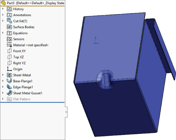
- Extrude the open sketch up to the vertex of the shorter flange as shown in the following graphic. Set the thickness to 0.025 inch, and the material to the inside. (If the material goes to the outside, you will have edge-to-edge contact between the existing body and the new feature, which constitutes a zero-thickness edge and thereby produces a new body rather than merging with the existing body.)

- Use the Convert Insert Bends feature (this may not be on the toolbar by default, so use Insert ➢ Sheet Metal ➢ Bends if necessary). Set the Bend Radius to 0.30 inch and the Auto Relief to 0.50 inch. Accept the feature. This will give you the situation shown shown here.
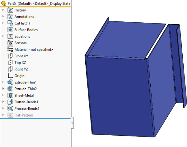
- Use the edge flange to add a new flange on the remaining open end of the box. This doesn't seem like a big deal, but it combines new (Base Flange) and old (Insert Bends) methods for working with SolidWorks sheet metal.
- Flatten the part to make sure it is correct.
- Master It The final Sheet Metal method is Convert To Sheet Metal. Follow these steps:
- Make a 3D box, 3 × 4 × 6 inches.
- Use the Shell feature to make it into a 0.025-inch thin wall part and remove one 6 × 4 face.
- Use the Convert To Sheet Metal feature with the following settings:
- Select the bottom face as the fixed entity.
- Select the four edges around the bottom face as bend edges.
- Under Corner Defaults, select Open Butt,0.05″ gap and 0.5 overlap ratio.
- For Auto Relief, use Tear with a 0.5 relief ratio.
- Initiate a Corner Relief feature, as in the following graphic, with the following settings:
- Two bend corners
- Rectangular relief for all corners
- 0.1″ slot length
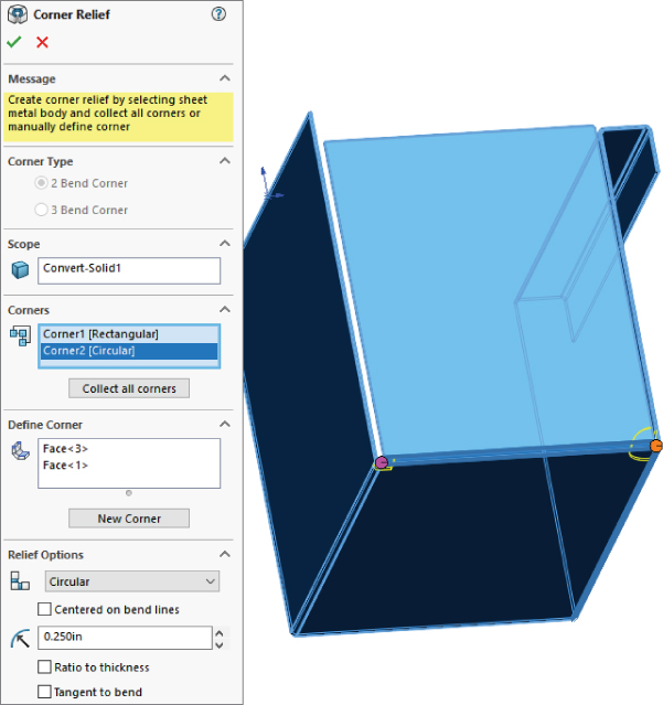
- Flatten the part to make sure it is correct.