
Chapter 5
Using Visualization Techniques
Part of the overall mission of SolidWorks software is to visualize geometry. Visualizing 3D CAD data is more than seeing shaded solids or shiny surfaces; it includes being able to see the interior and exterior at the same time and using sections, transparency, wireframe, and other tools or techniques. SolidWorks takes it so much further than just being able to see things in 3D; you can look at some parts of an assembly in wireframe while others are transparent and others are opaque. You can see a part with a reflective appearance. You can create section views in parts and assemblies to visualize internal details. This chapter will show you important capabilities that will expand how you can use SolidWorks and maybe even change the way you use the tools or look at modeling tasks.
Manipulating the View
![]() One of the most important skills in SolidWorks is manipulating the view. (Figure 5.1 shows the Heads-Up View toolbar, an easy way to access most visualization tools.) This is something you'll do more frequently than any other function in SolidWorks, so learning to do it efficiently and effectively is very important, whether you look at it as rotating the model or rotating the point of view around the model. The easiest way to rotate the part is to hold down the middle mouse button (MMB) or the scroll wheel and move the mouse. If your mouse does not have a middle button or a scroll wheel that you can use as a MMB, you can use the Rotate View tool in the menus at View ➢ Modify ➢ Rotate or via the RMB menu.
One of the most important skills in SolidWorks is manipulating the view. (Figure 5.1 shows the Heads-Up View toolbar, an easy way to access most visualization tools.) This is something you'll do more frequently than any other function in SolidWorks, so learning to do it efficiently and effectively is very important, whether you look at it as rotating the model or rotating the point of view around the model. The easiest way to rotate the part is to hold down the middle mouse button (MMB) or the scroll wheel and move the mouse. If your mouse does not have a middle button or a scroll wheel that you can use as a MMB, you can use the Rotate View tool in the menus at View ➢ Modify ➢ Rotate or via the RMB menu.

FIGURE 5.1 Use the Heads-Up View toolbar to easily access most visualization tools.
The Heads-Up View toolbar can be customized and disabled using the same method you use for all the other toolbars, through the Tools ➢ Customize dialog box.
For visualization, you cannot buy any hardware that’s quite as nice as a spaceball (3D mouse). It allows you to rotate with one hand and select with the other hand. It is also great for customizing buttons; depending on the model you get, it may even have some keyboard buttons such as Alt, Esc, and Ctrl right there on the device.
Using Arrow Keys
You can use the arrow keys on the keyboard to manipulate the view in predictable and controllable ways. You can use the Shift, Ctrl, and Alt keys to add to the behavior. The arrow keys enable you to rotate to the following views:
- Arrow: Rotate 15 degrees (to customize this setting, choose Tools ➢ Options ➢ View)
- Shift+arrow: Rotate 90 degrees
- Alt+arrow: Rotate in a plane flat to the screen
- Ctrl+arrow: Pan
Using the Middle Mouse Button
Most, if not all, mice sold today have middle mouse buttons (MMBs), usually in the form of a clickable scroll wheel. The MMB or scroll wheel has several uses in view manipulation:
- MMB alone: Rotate
- Click or hover: Work on an edge, a face, or a vertex with MMB and then drag MMB: Rotate around selected entity
- Ctrl+MMB: Pan
- Shift+MMB: Zoom
- Double-click MMB: Zoom to fit
- Scroll with wheel: Zoom in or out (to reverse direction of the zoom setting, choose Tools ➢ Options ➢ View)
- Alt+MMB: Rotate in a plane flat to the screen
When you're rotating the model view with the MMB, the view can easily get into a state where it's hard to see. Using the Rotate About Scene Floor option, however, makes this easier. Figure 5.2 shows this option in the RMB menu. You may see documentation that describes this as “lock vertical axis,” but it does not do that. “Lock vertical axis” would be if the model were sitting on a turntable going around. The Rotate About Scene Floor option seems to understand which way is “up,” and it doesn't allow the view to proceed in such a way that the model gets turned upside down easily. It's possibly more difficult to describe in writing than to just try it—so just try it. You may agree that this should have been the default method for rotation.

FIGURE 5.2 Using the Rotate About Scene Floor option
To change the floor position or orientation, go to the DisplayManager tab of the FeatureManager area, right-click Scene, and select Edit Scene. In the Floor panel, change the setting in the Align Floor With selection box and select the appropriate plane or Bottom View Plane.
As a caution, you may be prevented from accessing the Edit Scene PropertyManager if you are using the Plain Viewport Background color (Tools ➢ Options ➢ Colors ➢ Background Appearance). This uses System Options to determine the background for each document rather than allowing each document to control its own background. To access the Scene options, you have to change to Use Document Scene.
Using Mouse Gestures
Mouse gestures are an interface method that you can customize to do anything a SolidWorks toolbar button can do, but by default, it controls view orientation. Figure 5.3 shows the default configuration of the mouse gesture donut.
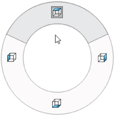
FIGURE 5.3 Click+drag the right mouse button (RMB) to access the commands on the donut.
It may take a little time for you to get used to the mouse-gestures interface. It works best when you understand what the commands are before you use them, so you can invoke the Top View command in a single motion, without pausing to see where each command is located on the donut. For this reason, it might be better to limit the donut to four commands rather than eight or 12 and to set it up intuitively such that the top view is an RMB stroke up, a right view is an RMB stroke to the right, and so on.
You can customize the mouse-gestures donut in the Tools ➢ Customize ➢ Mouse Gestures. This works much like the Keyboard (hotkey) customization, where you can turn gestures on or off, set the mouse gesture donut to two, four, eight, or 12 sections, and set any gesture direction to any available command.
Using the View Toolbar
The View toolbar, shown in its entirety in Figure 5.4, contains the tools that you need to manipulate the view in SolidWorks. Not all the available tools are on the toolbar by default, but I have added them here for this image. To customize your own View toolbar, you must use choose Tools ➢ Customize from the menu and select the Commands tab. Then click the View toolbar, and either drag items from the Customize dialog box to the View toolbar to add them or from the View toolbar into the empty graphics area to remove them. You can use all these tools with part and assembly models, but only a few of them with drawings.
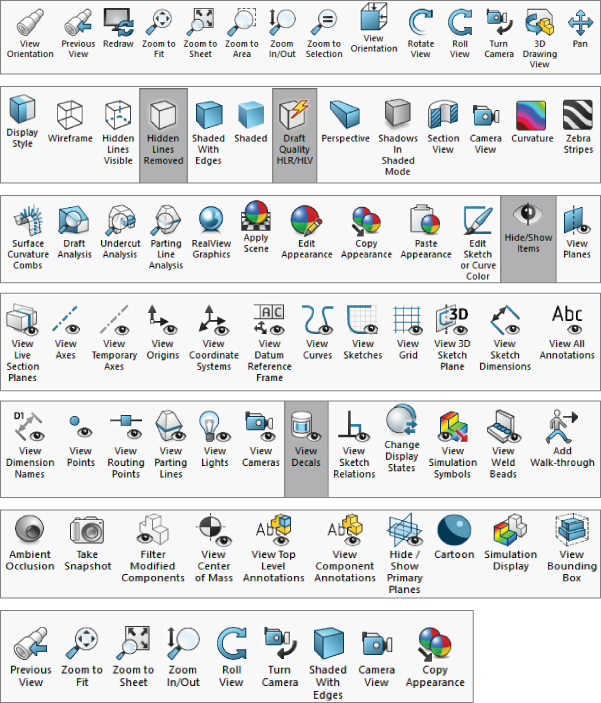
FIGURE 5.4 The View toolbar tools
The toolbar that holds tools for direct access to standard named views such as Front, Top, and Normal To is called the Standard Views toolbar and is described later in this chapter. The Add Walk-through tool is discussed more in Chapter 22, “Working with Large Scale Design,” and Chapter 23, “Animating with the MotionManager.” This is a means of creating an animation for a large-scale design. The Ambient Occlusion option is covered in this chapter, and it simply adds self-cast shadows to a model to make it look more realistic.
The Take Snapshot option works like the combination of a custom-named view and a display state. It allows you to return to a particular view of an assembly with parts hidden or shown as they were when you took the snapshot. You remain “in” the snapshot until you click the button to exit it, much like Isolate. You can find the saved snapshots in the DisplayManager on the Scene, Lights, And Cameras tab. The Filter Modified Components option makes any parts that have not been modified transparent, so that what you see as opaque are the parts that have been changed.
Adding Scrollbars and Splitters
An option exists to add scrollbars and view pane splitters to the graphics window. To use it, choose Tools ➢ Options ➢ Display/Selection, Display Scrollbars in graphics view. This selection is grayed out if any SolidWorks documents are open (so you must close all SolidWorks documents to change it). When you zoom in such that the part, assembly, or drawing is partially off the screen, the scrollbars activate on the right side and bottom of the SolidWorks window, enabling you to scroll up and down as well as left and right to pan the view. Scrollbars and splitters are turned off by default. You cannot turn off one or the other; scrollbars and splitters come as a package deal.
Figure 5.5 shows a detail of the bottom-right corner of the SolidWorks graphics window, where you find the scrollbars and splitters. Notice the cursor in the lower right, over one of the splitters. The splitters can be easy to miss if you do not know what they look like.
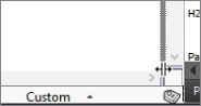
FIGURE 5.5 Scrollbar and splitter controls can be turned on or off.
The splitters enable you to split the main graphics window into multiple view ports. The options are two ports horizontally, two ports vertically and four ports, two horizontal and two vertical for a total of four view ports per document. The splitter bars are located at the intersection of the scrollbars in the lower-right corner of the graphics window. Of course, you can also use the icons on the View Orientation box for splitting the view into two vertical ports, two horizontal ports, or four ports.
After a viewport has been split, you can remove the split with the toolbar icons, either by dragging the border back to the edge of the display window or by double-clicking the split border. If the view has been split into four, you can set it back to a single viewport by double-clicking the intersection of the horizontal and vertical port borders.
Using the Magnifying Glass
You can invoke the Magnifying Glass by pressing G and dismiss it when you select something or when you press Esc. To change the hotkey it is associated with, choose Tools ➢ Customize ➢ Keyboard. Magnifying Glass is listed in the Other category. The Magnifying Glass is intended to magnify a small area of the view to enable you to make a more precise selection without zooming.
The magnified area follows your cursor as it moves, and you can zoom in and out by scrolling the MMB. Ctrl+dragging the MMB keeps the Magnifying Glass centered on the cursor. Pressing Alt creates a section view parallel to the view current, and scrolling the wheel with the Alt key pressed moves the section plane farther away or closer. Figure 5.6 shows the Magnifying Glass in operation, cutting a section view through a part.
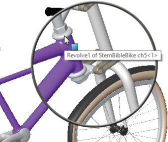
FIGURE 5.6 Using the Magnifying Glass with the section view
Clicking the Triad Axes
The Triad is the multicolored coordinate axis in the lower-left corner of the SolidWorks graphics window. You generally use it passively to see how the view is oriented and to get X, Y, Z reference directions for features that need them. To use the Triad to actively control the view orientation, try the following:
- Click an axis: The view rotates to point this axis out of the screen.
- Click an axis a second time: This axis points into the screen.
- Shift+click an axis: This view spins 90 degrees about that axis (using the right-hand rule).
- Alt+click an axis: This view spins 15 degrees (or the default view rotation angle) around the axis.
When you are in a named view, the name of the view is shown in the lower-left corner under the Triad. This includes standard named views and custom named views. Anything that shows up in the View Orientation box (accessed by the spacebar) displays a name in the corner. Figure 5.7 shows the Triad and the named view in the lower-left corner.
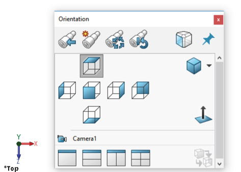
FIGURE 5.7 The Triad, named view, and View Orientation box
By Shift+clicking an axis of the Triad, the view is rotated 90 degrees from the original orientation about that axis. Alt+clicking rotates the view around the clicked axis by the view rotation increment set in Tools ➢ Options ➢ View, which is 15 degrees by default. Pressing Ctrl in conjunction with any of these causes the view to rotate in the opposite direction. Therefore, if pressing Shift+click makes the view rotate against the right-hand rule about the clicked axis, pressing Ctrl+Shift+click makes the view rotate with the right-hand rule.
Using the View Tools
SolidWorks has many additional tools for managing the view, and you can easily access them through the Heads-Up View toolbar, hotkeys, RMB menu, View Orientation box, or the normal toolbars and menus.
The tools in this section help you to control how you view parts and assemblies. The following tools are mainly found in the View, View ➢ Display, and View ➢ Modify menu areas.
 Zoom To Fit: This resizes the contents of the graphics window to include everything that is shown in the model. You can also access this command by pressing the F key or double-clicking with the MMB.
 Zoom To Area: When you drag the diagonal of a rectangle in the display area, the display zooms to fit it to the current window. The border size around the fit area is fixed and cannot be adjusted. This only zooms in, not out.
 Zoom In/Out: Drag the mouse up or down to zoom in or out, respectively. You can also access this command by holding down the Shift key and dragging up or down with the MMB. The hotkey Z and Shift+Z work for Zoom Out and Zoom In, respectively. The percentage of the zoom is a fixed amount and cannot be adjusted. You can also use the scroll wheel to zoom in and out, and if you are accustomed to using a different CAD product where the scroll works the opposite way, a setting exists at Tools ➢ Options ➢ View that allows you to reverse the function of the scroll wheel.
 Zoom To Selection: This resizes the screen to fit the selection. You can also access this command by right-clicking or left-clicking a feature in the FeatureManager. For example, if you select a sketch from the FeatureManager and right-click and select Zoom To Selection, the view positions the sketch in the middle of the screen and resizes the sketch to match the display. The view does not rotate with Zoom To Selection.
- Zoom About Screen Center: This enables you to zoom straight in and straight out. This tool is off by default. The default behavior is that zooming with the scroll wheel works around the cursor. If the cursor is off to one side, zooming in and out can cause the view to “walk” away from that side. Turning on Zoom About Screen Center is not dependent on the location of the cursor. If you are frustrated with how zooming with the scroll wheel works, try this setting and see if you like it better. This command is found only in the menus at View ➢ Modify and does not have an icon.
 Rotate View: This enables you to orbit around the part or assembly using the left mouse button (LMB). You can also access this command by using the MMB without the toolbar icon.
 Roll View: This spins the view on the plane of the screen, similar to Rotate View with the Alt key.
 Pan: This scrolls the view flat to the screen by dragging the mouse. You can also access this command by holding down the Ctrl key and dragging the MMB without using the toolbar icon; another way to access it is with Ctrl+arrow.
 3D Drawing View: This enables you to rotate the model within a drawing view to make selections that would otherwise be difficult or impossible. This is available only in drawing documents.
 View Orientation (Standard Views flyout) toolbar: View Orientation is discussed later in this chapter. The flyout enables you to access all the Standard Views tools. This button is also called the View Orientation flyout, depending on where you see it.
 Wireframe: This displays the model edges without the shaded faces. No edges are hidden.
 Hidden Lines Visible (HLV): This displays the model edges without the shaded faces. Edges that would be hidden are displayed in a font.
 Hidden Lines Removed (HLR): This displays the model edges without the shaded faces. Edges that are hidden by the part are removed from the display.
 Shaded With Edges: The model is displayed with shading, and edges are shown using HLR. Edges can all be a single color that you set in Tools ➢ Options ➢ Colors (typically black), or they can match the shaded color of the part. Tools ➢ Options ➢ Document Properties ➢ Colors is where you find the document-specific setting to use the same color for shaded and wireframe display, which becomes very useful in an assembly when all the parts shown in wireframe are the same color as they are when they are shaded, instead of all being black.
 Shaded: The model is displayed with shading, and edges are not shown.
 Shadows In Shaded Mode: When the model is displayed shaded, a shadow displays on a plane parallel to the floor as established in the scene. The shadow is not necessarily on the floor, but on the plane at the furthest extent of the model parallel to the floor.
 Section View: This sections the display of the model. Figure 5.8 shows the Section View command at work. You can use up to three section planes at once. Solid and surface models, as well as assemblies, can be sectioned. You can use the spin boxes, enter numbers manually, or drag the arrows that are attached to the section planes to move the section through the model. Section planes can also be rotated by dragging the border of the plane. Parts can be omitted from the cut, or the cut parts can be transparent. You can show the cut caps or leave the cuts looking hollow.

FIGURE 5.8 Sectioning a 3D model
- Clicking the checkmark icon in the Section View PropertyManager enables you to continue working with the sectioned model, although you may not be able to reference edges or faces that are created by the section view. It is only a displayed section; the actual geometry is not cut.
- Section views can be saved either to the View Orientation box or to the Annotation View folder, which enables 3D section views to be reused on the drawing. When you are working in a section view, if you want to alter it, you can access Modify Section View through the menus at View ➢ Modify ➢ Section View. You should notice that no toolbar icon exists for modifying a section view. You have to access this command through the menus or by turning off the Section View tool and then turning it back on. You might also notice that Modify Section View is available in the hotkey assignment area, Tools ➢ Customize ➢ Keyboard.
- The orange interface elements allow you to move or rotate the section, which can also be done in the PropertyManager. Notice the many options in the PropertyManager.
- You can section by 2D planes (act as cutting planes) or by 3D zones (bounding box segmented into solid zones by section planes)
I encourage you to experiment with this tool to see what it can do.
 RealView: This creates a more realistic reflective or textured display for advanced material selections. This feature does not work with all graphics hardware, so check the SolidWorks system requirements website to see if it supports your hardware. An entire section of this chapter is devoted to the various tools available with RealView graphics.
 Cartoon: This applies a cartoonish, less realistic appearance to the model. It creates a harsh lighting and a different type of shadow that doesn't rely on shadow settings. It is an effect you may want to experiment with, especially when using the edge and silhouette edge display options.
 Ambient Occlusion: This option displays shadows that the part casts on itself. It is particularly useful when a part or assembly has an interior area that can be seen from outside the model. The interior area will be shown in shadows with this setting on. The setting may affect performance especially on large assemblies.
 View Bounding Box: This option enables you to turn on the display of the bounding box (Insert ➢ Reference Geometry ➢ Bounding Box). The bounding box encloses the entire model (parts only) and looks like the edges of a cube created in a phantom-line 3D sketch.
 Apply Scene: This enables you to apply a scene to your document background. It may also turn off the system background color you are using.
 Edit Appearance: This enables you to apply and edit colors, textures, and materials to faces, bodies, features, parts, and components.
 Copy Appearance: This enables you to copy an appearance from the model to the Clipboard.
- Paste Appearance: This enables you to paste a copied appearance onto a model.
 Draft, Undercut, and Parting Line Analysis: These display options enable you to evaluate the manufacturability of plastic and cast parts. These three types of geometric analysis are discussed in more detail in Chapter 12, “Editing, Evaluating, and Troubleshooting.”
 Simulation Display: If your model contains results from a stress analysis, this button will allow you to display those results on your model.
 Walkthrough: The Walkthrough helps you create an animation that records a movie as if you were walking through a part or assembly.
 Change Display States: Display states help you retain visual or display settings for a document, and this tool enables you to switch between stored states.
 Hide All Types: Any of the icons with a picture of an eye on them can be used to show or hide the entity depicted in the icon. This includes planes, axes, sketches, curves, relations, parting lines, decals, and so on. You can access these icons quickly from the Heads-Up View toolbar. The eye icon on its own is Hide All Types, and it toggles each of these individual settings.
Zebra Stripes and Curvature
![]() Zebra Stripes, another geometrical analysis tool that helps you visualize the quality of transitions between faces across edges, simulates putting a perfectly reflective part in a spherical room where the walls are painted with black-and-white stripes. In high-end shape design, surface quality is measured qualitatively using light reflections from the surface. Reflecting stripes make it easier to visualize when a transition between faces across an edge is not smooth. Zebra Stripes can help you identify these three cases (see Figure 5.9):
Zebra Stripes, another geometrical analysis tool that helps you visualize the quality of transitions between faces across edges, simulates putting a perfectly reflective part in a spherical room where the walls are painted with black-and-white stripes. In high-end shape design, surface quality is measured qualitatively using light reflections from the surface. Reflecting stripes make it easier to visualize when a transition between faces across an edge is not smooth. Zebra Stripes can help you identify these three cases (see Figure 5.9):
- Contact: Faces intersect at an edge but are not tangent across the edge, such as at the edges of a cube. This condition exists when stripes do not line up across the edge.
- Tangency: Faces are tangent across an edge but have different radii of curvature on either side of the edge (noncurvature continuous), such as between a fillet face and an adjacent face. This condition exists when stripes line up across an edge, but the stripe is not tangent to itself across the edge.
- Curvature continuity: Faces on either side of an edge are tangent and match in radius of curvature. Zebra Stripes are smooth and tangent across the edge.
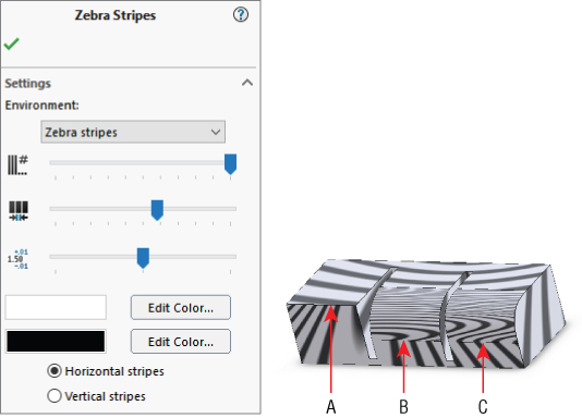
FIGURE 5.9 Zebra Stripes help you visualize the qualities of curvature.
In Figure 5.9, the Zebra Stripes in example A do not match across the edge labeled A at all. This is clearly the nontangent, contact-only case. Example B shows that the stripes match in position going across the indicated edge, but they change direction immediately. This is the tangent case. Example C shows the stripes flowing smoothly across the edge. This is the curvature continuous case.
You can use the remaining icons in the View toolbar to toggle the display of various types of entities from reference geometry to sketches.
![]() Curvature colors the model with various colors depending on the local surface curvature. Mathematically, curvature is the inverse of radius, so c = 1/r. A large radius is a small curvature and vice versa. Generally, on models where you are looking at curvature, you are looking for sudden changes, flat spots, constant radius, or inflections. Figure 5.10 shows a model of a cricket bat with the curvature displayed.
Curvature colors the model with various colors depending on the local surface curvature. Mathematically, curvature is the inverse of radius, so c = 1/r. A large radius is a small curvature and vice versa. Generally, on models where you are looking at curvature, you are looking for sudden changes, flat spots, constant radius, or inflections. Figure 5.10 shows a model of a cricket bat with the curvature displayed.
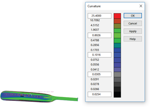
FIGURE 5.10 The Curvature display helps you evaluate properties of smooth models.
You can control the colors for various curvature values at Tools ➢ Options ➢ Document Properties ➢ Model Display ➢ Curvature using the table shown in Figure 5.10.
View Orientation
![]() The View Orientation dialog box and the Standard Views toolbar are very similar to one another. View Orientation is the more modern of the interfaces. The View Orientation dialog box and the View Selector are shown in Figure 5.11.
The View Orientation dialog box and the Standard Views toolbar are very similar to one another. View Orientation is the more modern of the interfaces. The View Orientation dialog box and the View Selector are shown in Figure 5.11.

FIGURE 5.11 The View Orientation dialog box and the View Selector
![]() You can access the View Selector independently from the View Orientation dialog box by pressing Ctrl+spacebar or by accessing it from the Standard Views toolbar. The View Selector graphic enables selection of various angled unnamed views, giving you a visual preview for selection. The View Orientation dialog box contains the following controls:
You can access the View Selector independently from the View Orientation dialog box by pressing Ctrl+spacebar or by accessing it from the Standard Views toolbar. The View Selector graphic enables selection of various angled unnamed views, giving you a visual preview for selection. The View Orientation dialog box contains the following controls:
 Pushpin: This keeps the dialog box active.
 New View: This creates a new custom-named view.
 Update Standard Views: This sets the current view to be the new Front view; all other views update relative to this change. This also updates any associated drawing views but does not move any geometry or change plane orientation.
 Reset Standard Views: This resets the standard views so that the Front view looks normal to the Front plane (Plane1, XY plane).
 Previous View (undo view change): You can access this tool by pressing the default hotkey Shift+Ctrl+Z.
![]() The Normal To option has four modes of operation:
The Normal To option has four modes of operation:
- First Mode: With nothing selected, Normal To will find the nearest orthogonal view.
- Second Mode: Click a plane, planar face, or 2D sketch. When you click Normal To, the view reorients normal to the selected plane, face, or sketch and zooms to fit the model in the view. This method is shown in Figure 5.12.

FIGURE 5.12 Using Normal To on an angled face
- Third Mode: Click Normal To a second time. The view rotates 180 degrees to display the opposite direction.
- Fourth Mode: After making the first selection, Ctrl+select another planar entity. The view is normal to the first selection, and the second selection is rotated to the top. This method is shown in Figure 5.13.
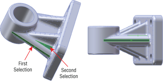
FIGURE 5.13 Using Normal To with a second selection to define the top
Annotation Views
Annotation views enable you to group annotations that were made in a 3D model into views that will be used on the drawing. They are collected under the Annotations folder in the FeatureManager for parts and assemblies. Annotation views can be created automatically when 3D annotations are added or created manually. An Unassigned Items annotation view acts as a catchall for annotations that are not assigned to any particular views. In the 3D model, you can use the views to reorient the model and display annotations. As mentioned earlier, annotation views can also capture a model section view to be shown in a drawing view.
Annotation views are listed in the Annotations folder in the FeatureManager of the document where they are created. Right-clicking the Annotations folder provides all the options for Annotation views. The Annotation views are shown for the Chapter5SampleCasting part in Figure 5.14.
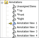
FIGURE 5.14 Annotation views for Chapter5SampleCasting.sldprt
Using the DisplayManager
![]() The DisplayManager organizes all the display and visual information into a form that makes it easier to understand and control. The DisplayManager lists Appearances, Decals, Scenes, Lights, and Cameras. You can find the DisplayManager as a tab in the FeatureManager window area. Figure 5.15 shows the Appearances data for a part with a material and color applied to two faces and a feature.
The DisplayManager organizes all the display and visual information into a form that makes it easier to understand and control. The DisplayManager lists Appearances, Decals, Scenes, Lights, and Cameras. You can find the DisplayManager as a tab in the FeatureManager window area. Figure 5.15 shows the Appearances data for a part with a material and color applied to two faces and a feature.

FIGURE 5.15 Using the DisplayManager to manage appearances
Appearances in SolidWorks are a combination of color and texture. In order to have appearances display and sort in the DisplayManager, you have to first apply appearances. Most of the appearances are meant to look like idealized materials in real life. Remember that materials are applied separately and control physical properties such as density, strength, and so on. Appearances deal with cosmetic properties. Polished, cast, knurled, machined, sand-blasted, and other surface finish types are available to add realism to your models.
Applying Appearances
You can apply appearances to faces, bodies, features, parts, assembly components, or even the top-level assembly. Even if you don't apply an appearance, every part and assembly template starts with a default appearance (except very old templates), which is white, glossy plastic.
You can apply appearances in several ways:
- Double-click: Double-clicking an appearance in the Appearances panel of the Task pane applies the appearance to the document (part or assembly).
- Drag-and-drop: Dragging an appearance from the Appearances panel of the Task pane enables you to drop it on geometry in the graphics window. When you do this, the appearance palette pops up and presents you with several options. Figure 5.16 shows this toolbar with the options for Face, Feature, Body, and Part.
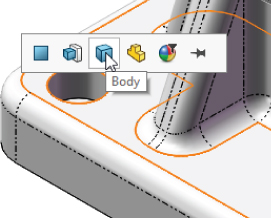
FIGURE 5.16 Determining a target for the appearances after drag-and-drop
- Appearance palette: If you pin the Appearance palette, the workflow reverses. Select the type of entity to which you want to apply the appearance and select model faces.
- Appearance filter: The Appearance filter enables you to change all items of a given appearance to a new appearance. Just drag the new appearance onto any face with the old appearance, and click the Appearance filter when it appears. All other items with that particular appearance are changed to the new appearance.
- Context toolbar: You can also invoke the Appearance function from the context bars (left-click or right-click). You can do this with preselection or no selection. This method also gives you options for the target to which to apply the appearance, face, feature, body, or part. Figure 5.17 shows this method.

FIGURE 5.17 Determining a target for the appearances after drag-and-drop
You can copy and paste appearances from the DisplayManager (or the model) onto the model. To distinguish between copying geometry and copying appearances, the appearance copy shortcut is Ctrl+Shift+C, and the appearance paste shortcut is Ctrl+Shift+V.
DIFFERENTIATING APPEARANCES AND MATERIALS
It is easy to confuse appearances and materials. The biggest reason for this is that, in many cases, appearances have the same names as materials, and the texture associated with the appearance typically also has the name of a material. SolidWorks has appearances with names such as high-gloss plastic, wrought iron, and chromium plate. It may become even more confusing because materials (which you can assign from the FeatureManager on the left) have appearances (which you assign from the Task pane on the right) assigned to them. For example, you could assign an appearance called polished aluminum to a material called AISI 304.
You cannot use appearances to assign mass properties (such as density or stiffness) to a part, but you can use materials to assign an appearance as well as mass properties to a part. Figure 5.18 shows the RMB menu for editing material, which you invoke from the Material folder in the FeatureManager.
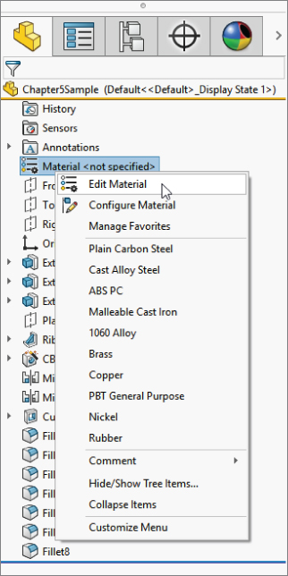
FIGURE 5.18 Editing a material
Materials assign properties to your parts for drawing hatch and mass properties, as well as simulation. Notice in Figure 5.19 that the second tab allows you to assign an appearance to the material. You can use this interface to create your own custom materials, which automatically apply appearances to your parts.

FIGURE 5.19 Editing or creating custom materials
UNDERSTANDING APPEARANCES
Appearances are made up of a combination of color, illumination properties, a surface finish image, and image-mapping settings. You can control all these options in the Advanced interface of the Appearances PropertyManager, as shown in Figure 5.20. To access this interface, click the Appearance icon in the Heads-Up View toolbar, and click the Advanced button at the top of the PropertyManager.
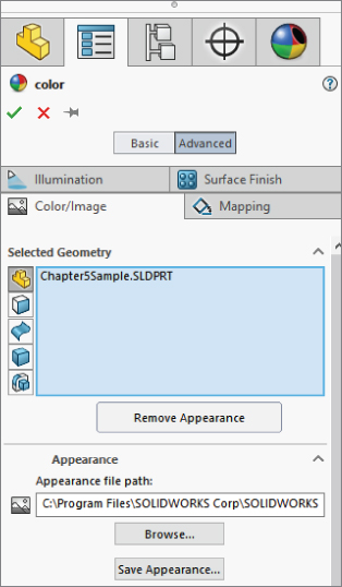
FIGURE 5.20 Controlling the components of appearance
You can adjust the default appearances that install with SolidWorks when you apply them to your models. For example, you can apply a shiny, reflective appearance such as Stainless Steel and then adjust its color to blue or red. You could apply a cast-iron appearance and then increase the roughness. You might apply a brushed-aluminum appearance and change the direction of the brush lines. You could apply a reflective-glass appearance and then reduce the reflectivity and increase the transparency. You might apply a knurled-steel appearance to a cylindrical part and adjust the mapping so the knurled image does not smear improperly across a face. Figure 5.21 shows the contents of the Color/Image, Mapping, Illumination, and Surface Finish tabs of the Appearances PropertyManager, where you can adjust all these settings and more.
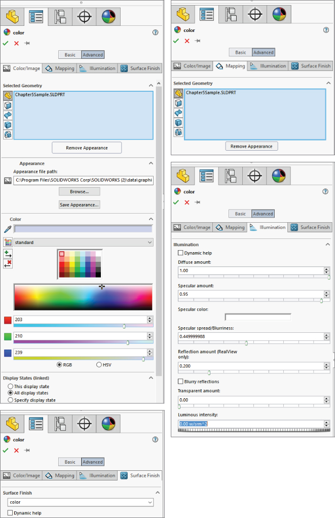
FIGURE 5.21 Adjusting the display properties in the Appearances PropertyManager
UNDERSTANDING OVERRIDES
Keeping track of colors and appearances in SolidWorks can be difficult. Many users have difficulty understanding when one color overrides another color and how to remove layers of applied colors or appearances. This functionality is called Overrides.
Here is the hierarchy that SolidWorks uses when applying colors (appearances), listed from lowest priority to highest:
- Default
- Part
- Body
- Feature
- Face
- Component
- Assembly
You should read this list with the words “…is overridden by…” between the items. As you can see, the default appearance is overridden by anything else, and an appearance that you apply to the assembly overrides everything else.
In Figure 5.15, the DisplayManager shows the colors and appearances listed by history, which refers to the order in which they were added to the model. Figure 5.22 shows the appearances sorted by hierarchy, using the order established by Overrides. The Sort Order drop-down list allows you to select from History, Hierarchy, and Alphabetical sorting.

FIGURE 5.22 Sorting appearances and colors by hierarchy
Appearances can be difficult to understand, but the best way to visualize them is to use the View Appearances tab of the DisplayManager, shown previously. The DisplayPane flyout from the FeatureManager is tempting, but it is incomplete. It does not show appearances applied to faces, because individual faces are not listed in the FeatureManager unless they are also bodies or features. It sounds complicated, right? Just use the View Appearances tab of the DisplayManager, and you will have access to appearances applied to your parts and assemblies.
As an alternative, you can select a face and probe for the various “layers of paint” applied to it. You can do that by clicking the “beachball” icon on the context toolbar. You get a clear picture of the various “layers of paint” applied on the face you selected.
USING APPEARANCES WITH DISPLAY STATES
Display States allow you to have named sets of display settings for parts and assembliesl; which are covered in detail in this chapter. You also need to understand configurations (see Chapter 11, “Working with Part Configurations”) to completely grasp the use of appearances with Display States. You can assign appearances to apply to all Display States or just to the current Display State. Display States, in turn, can be linked or unlinked to configurations, and some display properties, such as color, can be controlled by configurations. The control of appearances and colors for Display States and configurations is convoluted at best. This is a warning that mixing changes to these four items can result in colors that you can neither remove nor apply. It is difficult to say how much of this is due to bugs and how much is due to convoluted logic and too many sources of control. You can control the setting for the Display State to which an appearance change applies. You do this in the Display States panel at the very bottom of the Appearances PropertyManager.
You can find the Display States interface at the bottom of the ConfigurationManager, as shown in Figure 5.23.

FIGURE 5.23 Controlling appearances with Display States
REMOVING APPEARANCES
You can think of multiple appearances applied as overrides within the part as an old chair with many layers of paint. In this case, you can remove those layers of paint one by one until you get down to the base material, which in this case is the default material: white plastic.
Look at Figure 5.24. Notice the red X to the right of each entity—face, feature, body, and part—and another one at the bottom. Each red X enables you to remove one or more layers of paint from this part. You can remove any appearance applied at any level just by clicking the red X. Clicking the bottom red X removes all the overrides (all the face, feature, body, part, and other colors that have been applied) and assigns the default appearance for that part. You may want to open this part from www.wiley.com/go/mastersolid, because the book is in black and white, and does not convey color well. The part name is Chapter 5 – bracket override.sldprt.

FIGURE 5.24 Removing appearances from a part
You can assign the default appearance in a part or assembly template by saving it with a name reflecting the material. As an alternative, you can reassign it in an existing part. To assign or reassign the appearance, open the Appearances, Scenes, And Decals tab in the Task pane, find an appearance that you like, and right-click it. Figure 5.25 shows the menu that appears.
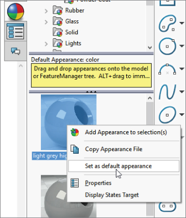
FIGURE 5.25 Assigning a default appearance
To save this appearance to a part template, assign the default appearance in an empty part document with settings that you want to use, set the default appearance, and save the empty part as a part template with a name indicating the appearance. You may also want to assign a corresponding material.
Using Decals
Decals are images applied to a part without rendering software. All decals used in a model are listed in the Decal area of the DisplayManager. To apply a decal, you can use the Appearances, Scenes, And Decals tab of the Task pane to access the stock or sample images, or you can right-click in the open area of the Decals DisplayManager and select Add Decal. This brings up the Decals PropertyManager, shown in Figure 5.26.
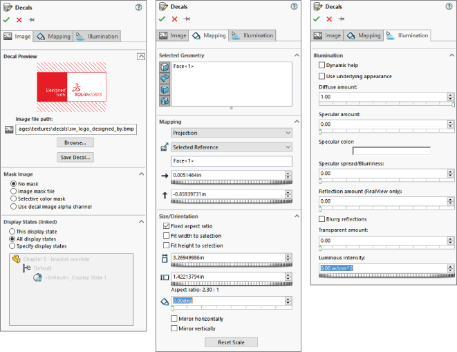
FIGURE 5.26 Working with the Decals PropertyManager
You can use *.bmp, *.jpg, *.tif, and *.png images as decals in SolidWorks. The images can be mapped onto flat, cylindrical, or spherical surfaces. You can use masks or images with an alpha channel to create transparent parts of the decal. You can also select a color of the image to set to transparent. Only *.tif and *.png images can use alpha channel transparency.
You can size, position, and rotate the decal on the screen with handles, as shown in Figure 5.27. You can use any of the corner nodes on the image to resize the decal. Dragging anywhere inside the image border moves the decal, and dragging the orange ring around the image rotates it. Decals can also emit light.

FIGURE 5.27 Sizing and positioning the decal
Using Scenes, Lights, and Cameras
Scenes, lights, and cameras are important for visualing and rendering. Rendering is not covered in this book, because PhotoView 360 and SolidWorks Visualize are not part of the SolidWorks Standard package. The Scene, Lights, And Cameras DisplayManager is shown in Figure 5.28.

FIGURE 5.28 Using the Scene, Lights, And Cameras DisplayManager
CONTROLLING SCENES
In SolidWorks, a scene is composed of three things: a background, which may be an image, a gradient, or a color; a floor, on which shadows and reflections are cast; and an environment, which is a wraparound 3D image (*.hdr or *.hdri—high dynamic-range image) that provides light to the model in a rendering and will reflect on the model if the model is a highly reflective material. If the environment is hidden, you see only the background. You can also hide the floor so there are no shadows or reflections, and the model will appear to hang in space.
Be aware that the small, square image shown for each scene in the Task pane is a thumbnail rendering of the scene and does not reflect how the scene will look in the graphics window. For most of this book, I have used the Plain White scene.
Floors and environments appear only when you do a rendering. If you want to remove shadows from the modeling window while you work, use the View Settings icon in the Heads-Up View toolbar to do this. This is shown in Figure 5.29.
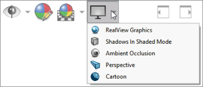
FIGURE 5.29 Turning off shadows in the modeling window
When you are using Real View Display, you can take advantage of a special setting called Ambient Occlusion. With this combination, the SolidWorks model can throw shadows on itself, and holes in the model appear in shadow. It gives some of the effect of a rendering, but it is just the RealView display.
Ambient Occlusion has some limitations; for example, it does not show shadows on the part while rotating, only when you stop rotating the view (unless you use Draft Quality Ambient Occlusion, found at Tools ➢ Options ➢ Display). It also only works when in Shaded mode (with or without edges).
Figure 5.30 shows a part with the various Ambient Occlusion settings. Ambient occlusion does slow down the graphics performance of SolidWorks, but it can also help a part look more realistic without you having to take the time to do a rendering. Depending on your graphics card and workstation, Real View, Ambient Occlusion, and other advanced graphics settings may or may not noticeably affect display calculation time. It is best practice, of course, to work without these advance settings, unless they do not affect performance.

FIGURE 5.30 This Ambient Occlusion scene gives more realistic shadows without rendering.
If you want to turn off reflections on the floor while modeling, you can apply a Basic scene or turn off the reflective floor in the Scene PropertyManager, as shown in Figure 5.31. From here you can also perform other common tasks, such as aligning the floor with a different plane, offsetting the floor, and adjusting the brightness of the scene.

FIGURE 5.31 The Scene PropertyManager allows you to turn off the reflective floor while modeling.
To apply a scene to a document, you can use the Appearances, Scenes, And Decals tab of the Task pane; expand the Scenes heading; choose from Basic, Studio, or Presentation scenes; and double-click or drag the scene into the graphics area. Note these differences between Basic, Studio, and Presentation scenes:
- Basic scenes use only a background color.
- Studio scenes use a gradient background.
- Presentation scenes use an HDRI image, so the image rotates with the part as you rotate the view.
SolidWorks scenes can be either document or system property. Document property is the default. This means that each document can have a different scene, and the scene will travel with the document when opened by different users. You can override the default with a system option, Tools ➢ Options ➢ Colors, and change the Background Appearance setting to Plain, Gradient, or Image, which gives control of the scene to the local computer. When a document that has been saved with a document scene is opened on a computer set to use system scenes, the system setting overrides the document setting.
If you right-click on the Scene folder in the SceneManager, SolidWorks will prompt you with a message to change any system scene setting to the document scene.
TURNING ON THE LIGHTS
All models have ambient light. (If there were no light, you wouldn't be able to see the model.) Additional light types are Directional, Point, Spot, and Sunlight. You can add lights by right-clicking the Lights folder in the DisplayManager and selecting one of the new light options shown in Figure 5.32.

FIGURE 5.32 Adding lights to the scene
The light appears as an icon in 3D space, which you can drag around. You can also use the PropertyManager for editing the light to key in a specific XYZ location for the light source or direction. Lights added to the scene can be turned on or off in SolidWorks.
The Ambient setting raises the overall brightness of the part, the Brightness setting refers to just the light, and the Specularity slider controls how lights shine or create “hot spots” on curved faces of models. You can even edit the color of a light to give a part a two-tone effect.
Lighting effects are most dramatic on curved parts. This is why adding even small fillets to a rectangular model can help make the part look more realistic for presentation purposes. Figure 5.33 compares a model with filleted edges to a model with perfectly sharp edges. The model with the fillets is also displayed with Real View and Ambient Occlusion to help it look more realistic.
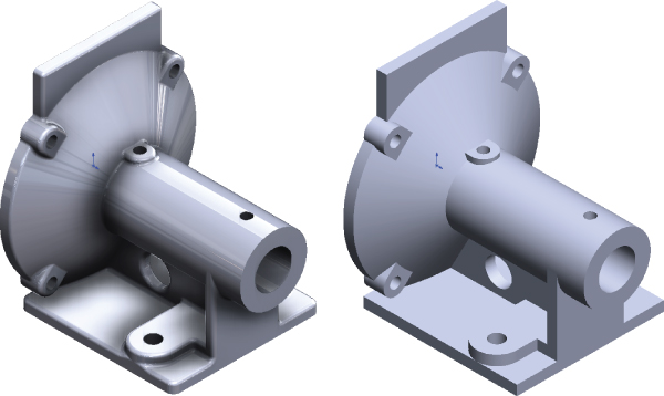
FIGURE 5.33 Demonstrating the difference between the appearance of a part with fillets and a part with sharp corners
Materials can also be set up to emit light, for the situations where you might want to have a light bulb, LED panel, or a car taillight in the model.
WORKING WITH CAMERAS
You create cameras through the RMB menu on the Scene, Lights, And Cameras DisplayManager, as shown in Figure 5.34. When you add a camera, an interface displays in the PropertyManager, as shown in Figure 5.35.

FIGURE 5.34 Adding a new camera with the Camera PropertyManager
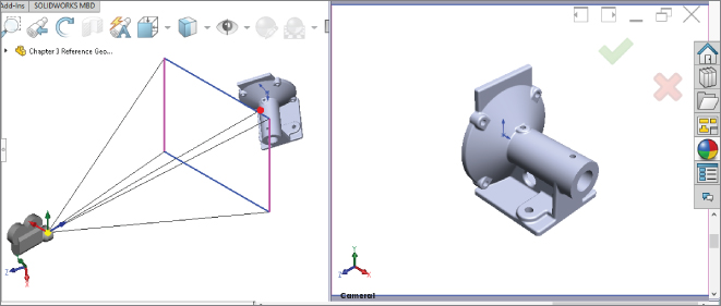
FIGURE 5.35 Positioning a camera with split windows
In this interface, you can position the Camera object by dragging the Triad. To resize the Field Of View box, use the controls in the Field Af View panel in the PropertyManager. In the graphics window, you can use the left panel to target and position the camera, while the right panel shows the view through the camera.
You get the most lifelike perspective from a lens setting of about 50 mm. Shorter distances produce wide-angle or fish-eye lens effects. Larger settings make it look like a telephoto lens. It should be noted that perspective within SolidWorks works much differently. Within SolidWorks, the perspective setting is based on how many object lengths you are away from the model. For example, if a model is approximately 2 feet tall, you would set your perspective as multiples of 2, so three model lengths would be 6 feet.
The Depth of Field panel of the Camera PropertyManager is not shown, because it requires that PhotoView be installed. Depth of field can make objects outside of the focus area slightly out of focus, which can greatly add to the realism of renders.
You can use three methods to switch the graphics window to the Camera view:
- Access the View Orientation dialog box by pressing the spacebar.
- The View Orientation dialog has a Camera View icon. The icon appears only if there is a camera in the model.
- As an alternative, go through the RMB menu on the camera in the Lights, Cameras, And Scene folder in the FeatureManager.
Be aware that there are two separate tools: Camera View and View Cameras. They look almost identical, except that View Cameras has a small eye in one corner of the icon. View Cameras allows you to see the placement of the camera; Camera View allows you to see what the camera sees.
When you switch the view to the Camera view, the regular Rotate View command does not function. Rotating the view means moving the camera. You can move the camera by editing the Camera properties, you can reposition the camera by dragging the Triad, or you can rotate the view while looking through the camera using the Turn Camera tool.
 Camera View: This views the model through a camera. You can use cameras for these purposes:
- View the model from a particular point of view.
- Create renderings with perspective and depth-of-field (focus) blur. This feature is available only when PhotoView 360 is installed.
- Animate the position and target of the point of view in an animation. This feature is available only when a Motion Study is active.
- Create a view inside a cavity or other occluded area.
 Turn Camera: This enables you to rotate the camera view when looking through the camera without editing the Camera properties. You must be looking through the camera and it must be unlocked for this to work. Dragging with the MMB does the same thing if the camera is unlocked.
 Draft Quality HLR/HLV: This toggles between low-quality (draft) and high-quality edge Hidden Lines Removed (HLR) or Hidden Lines Visible (HLV) display. This setting affects display speed for complex parts or large assemblies. When in Draft Quality mode, edge display may be inaccurate.
 Perspective: This displays the model in perspective view without using a camera. If you want to create a perspective view on a drawing, you must create a custom view in the View Orientation dialog box with Perspective selected. You can adjust perspective through View ➢ Modify ➢ Perspective by adjusting the relative distance from the model to the point of view. Relative distance is measured by the size of the bounding box of the model; therefore, if the model fits into a box roughly 12 inches on a side and the perspective is set to 1.1, the point of view is roughly 13 inches from the model. For more accurate perspective, you can use a camera.
USING REALVIEW
![]() RealView is the display technology behind the fancy appearances of SolidWorks models, such as ambient occlusion, reflective materials, and shadows. The reflections and lighting depend on RealView. If you turn off RealView or if you don't have hardware that supports it, you can't get the great displays. RealView does not affect rendering, just the live display. Check the system requirements listed on the SolidWorks website for information about whether your video card supports RealView.
RealView is the display technology behind the fancy appearances of SolidWorks models, such as ambient occlusion, reflective materials, and shadows. The reflections and lighting depend on RealView. If you turn off RealView or if you don't have hardware that supports it, you can't get the great displays. RealView does not affect rendering, just the live display. Check the system requirements listed on the SolidWorks website for information about whether your video card supports RealView.
You can even use RealView as a diagnostic tool for smooth transitions between surfaces because RealView appearances apply a reflective surface to a part and then apply a reflective background. This is essentially what the Zebra Stripes functionality is doing, but Zebra Stripes applies a specific reflective background to make examining curvature continuity across edges more straightforward.
You can turn RealView on or off by using the shiny sphere icon in the View Settings of the Heads-Up View toolbar. If this icon is grayed out, your system is not equipped with an appropriate RealView-capable graphics card.
The Display Pane
The Display pane flies out from the right side of the FeatureManager and displays a quick list of which entities have appearances, transparency, shown/hidden assigned. It also shows hidden parts or bodies for assemblies and multibody parts. The Display pane is shown in Figure 5.36.

FIGURE 5.36 The Display pane allows you to control display elements of your SolidWorks model.
This tool to some extent duplicates the DisplayManager, but it also provides a quick summary of most of the display information, including Wireframe/Shaded display mode, transparency, hide/show state, and color. It works in both parts and assemblies, and it's a highly valuable tool. Between the DisplayManager and the Display pane, you can easily manage one of the most confusing areas of the SolidWorks software: Appearances.
Applying Color Automatically to Features
You can use the settings found at Tools ➢ Options ➢ Document Properties ➢ Model Display to automatically color certain types of features with specific colors. For example, you can color all Shell features red as you create them.
This function has worked intermittently for many years. For example, you can assign Boss features to always be red, and that works. You can assign surface features to always be yellow, and it works for Extrude, Revolve, Planar, Offset, Loft, and Sweep surfaces, but not for Boundary, Fill, or Ruled.
Using Edge Display Settings
Earlier in this chapter, I discussed the Shaded With Edges display style. Sometimes this method is useful to see the breaks between faces, especially fillets. It is especially useful in assemblies when parts are different colors.
Taking this one step further, you can also utilize the tangent edge settings. These settings are found in the View➢ Display menu and also in the Heads-Up View toolbar. These are the settings:
- Tangent Edges Visible: This setting displays tangent edges as solid lines, just like all other edges.
- Tangent Edges As Phantom: This setting displays tangent edges in a phantom line font.
- Tangent Edges Removed: This setting displays only nontangent edges.
The Tangent Edges Removed setting leaves parts looking like a silhouette. I prefer the Phantom setting because I can easily distinguish between edges that will actually look like edges on the actual part and edges that serve only to break up faces on the model. The Tangent Edges Visible setting conveys no additional information and is the default setting. Figure 5.37 shows a sample part with Tangent Edges as Phantom, Tangent Edges Visible, Tangent Edges Removed, and Shaded (no tangent edge settings), respectively.
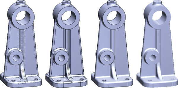
FIGURE 5.37 Samples of the tangent edge settings
Tutorial: Applying Visualization Techniques
Visualization is a key factor when you're working with SolidWorks software. Whether you are presenting a design to customers or management, or you are simply checking a design, being able to see the model in various ways is important. This tutorial guides you through using several tools and techniques.
- If the part named
Chapter5Sample.sldprtis not already open, open it from the download materials for this chapter. If it is open and changes have been made to it, choose File ➢ Reload ➢ OK. - Practice using some of the controls for rotating and zooming the part. In addition to the View Toolbar buttons, you should also use Z and Shift+Z (Zoom Out and Zoom In, respectively), the arrow keys, and the Ctrl+arrow, Shift+arrow, and Alt+arrow combinations.
- Use the MMB to select a straight edge on the part, and then drag it with the MMB. This rotates the part about the selected entity. Also apply this technique when selecting a vertex and a flat face.
- Select the name of the part at the top of the FeatureManager.
- Click the Edit Appearance button from the Heads-Up View toolbar at the top of the graphics window.
- Click the color you want in the Favorite panel. The model should change color. If you click and drag the cursor over the colors, the model changes color as you drag over each new color. You can also drag appearances from the Task pane. Figure 5.38 shows interfaces for both methods.

FIGURE 5.38 Color PropertyManager and the Appearances Task pane
- If the Color panel is not expanded, click the double arrows to the right to expand it. Select the colors you want from the continuous color map. Again, click and drag the cursor to watch the part change color continuously.
- Create a swatch. In the Favorites panel, select the Create New Swatch button and call the new swatch color file
BibleColors. - Select a color from the Color Properties continuous map; the Add Selected Color button becomes active. Clicking the button adds the color to the swatch palette. You can add several colors to the palette to use as favorites later.
- In the Appearance panel, move the Transparency slider to the right and watch the part become transparent.
- To prevent the Appearance window from closing after every change, click the pushpin at the top of the window.
- Click the green checkmark icon to accept the changes. Note that with the pushpin icon selected, the window remains available.
- Expand the flyout FeatureManager in the upper-left corner of the graphics window, as shown in Figure 5.39, so all the features in the part are visible.
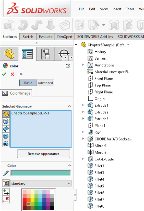
FIGURE 5.39 The Flyout FeatureManager
- Select the features Extrude1, Fillet7, and Fillet6 from the FeatureManager so they are displayed in the Selection list of the Color FeatureManager. Select a color from the BibleColors swatch palette that you just created.
- Click the checkmark icon to accept the changes and clear the Selection list.
- Select the inside face of the large cylindrical hole through the part, and assign a separate color to the face.
- Click the checkmark icon to accept the changes, and click the red X icon to exit the command.
- Expand the Display pane (the upper-right area of the FeatureManager). You should see color and transparency symbols for the overall part and color symbols for three features. There is no indication of the face color that is applied.
- Remove the colors. Open the Appearances window again, reselect the three features (Extrude1, Fillet7, and Fillet6), and click the Remove Color button below the Selection list. Do the same with the colored face of the cylindrical hole. Return the part transparency to fully opaque.
- Click the checkmark icon to accept the changes.
- Change the edge display to Shaded (without edges). Then change to a Wireframe mode. Finally, change back to Shaded With Edges.
- Use the Display Style drop-down in the Heads-Up View toolbar to cycle through the edge display options.
- Switch back to Shaded display.
- If you do not have a RealView-capable computer, skip this step. Ensure that the RealView button in the View toolbar is depressed. Click the Appearances/Scenes tab on the Task pane to the right of the graphics window. Expand Appearances ➢ Metal ➢ Steel; in the lower pane, scroll down to the Cast Carbon Steel appearance.
- Turn the part over, select the bottom face, and drag and drop the appearance from the Task pane. Apply the appearance just to the bottom face using the pop-up toolbar that appears. The rest of the part should retain the semireflective surface, as shown in Figure 5.40. Click the checkmark icon to accept the change.
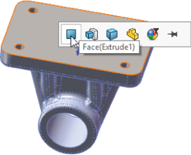
FIGURE 5.40 Applying an appearance to a face
- Click the Section View button on the View toolbar. Drag the arrows in the middle of the section plane back and forth with the cursor to move the section dynamically through the part, as shown in Figure 5.41. You can also rotate the section along various axes. Play around with this to get a feel for the capabilities of the command.
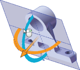
FIGURE 5.41 Applying a section view to a model
- Select the check box next to the Section 2 panel name, and create a second section that is perpendicular to the first.
- Click the green checkmark icon to accept the section. Notice that while in the Section View PropertyManager, the RealView material does not display, but after you close the dialog box, RealView returns.
The Bottom Line
- Visualization is one of the most important tools in SolidWorks.Visualization is a key function of the SolidWorks software. You will use these tools multiple times an hour and, in some cases, constantly throughout the day. Visualization can be an end to itself if you are showing a design to a vendor or client, or it can be a means to an end if you are using visualization techniques to analyze or evaluate the model. In both cases, SolidWorks presents you with an astounding list of tools to accomplish the task. The tools range from the analytical to the cosmetic, and some of the tools have multiple uses.
- Master It Practice using the keyboard and mouse display controls, including the arrows and modifier keys. Access the Orientation box with Ctrl+spacebar and manipulate the view using each of these tools. To become acquainted with the names of all the tools on toolbar, use the mouse to hover over the Heads-Up View toolbar. Make sure to look at all the drop-downs and flyouts.
- Master It Use the DisplayManager and the Task pane to access all of the information and tools to apply appearances and visual properties to your model. Make sure to use the DisplayPane flyout from the FeatureManger to have quick access to appearances applied to your part.
- Master It Acquaint yourself with all of the settings available in Tools ➢ Options ➢ Colors and ➢ Display. Don't forget the settings under Tools ➢ Options ➢ Document Properties ➢ Model Display. Create templates with the background and visual properties you want to use.