
Chapter 14
Getting More from Mates
Mates provide the glue that holds SolidWorks assemblies together. When properly handled, mates enable your assembly to react predictably to changes in parts in exactly the same way that sketch relations drive changes in part features. As a result, mates and sketch relations often have the same function and even the same weaknesses.
This chapter goes one step further with mates, by not simply putting parts together with Coincident and Concentric mates, but also mating parts when real-life situations such as tolerances, gaps, and symmetry become issues. You will also learn about the more advanced mate types that may be useful for special situations.
One of the assumptions made in this chapter is that assembly mates are not just used for positioning parts, but also for motion. Making motion work takes a little more than just establishing the right spatial relationship between parts; it usually also involves analyzing the open degrees of freedom.
Applying Mates
An average assembly of 100 parts is likely to have almost 300 individual mates. If you created these parts one at a time, taking perhaps 30 seconds for each mate, you would spend two and a half hours just applying mates. In this section, you will learn efficient mating strategies, as well as speedy techniques.
As you apply mates to parts in your assembly, keep in mind that SolidWorks has high-risk and low-risk mating schemes. High-risk schemes generally involve mate techniques that are easier but more likely to have problems later in the evolution of your model, such as lost references or conflicts with other mates. More stable mating schemes favor reference geometry (such as planes and axes, and possibly sketches) over model faces and edges.
Mating Through the Mate PropertyManager
The Mate PropertyManager is the default method for applying mates, and you used it briefly in Chapter 4, “Creating Simple Parts and Drawings,” while creating the simple assembly. The Mate PropertyManager interface is shown in Figure 14.1. You can create mates by preselecting entities before applying the Mate command or by selecting them after you open the Mate PropertyManager. The three types of mates are Standard, Advanced, and Mechanical.

FIGURE 14.1 The Mate PropertyManager interface
UNDERSTANDING THE MATE WORKFLOW
There are several different ways of making mates, and I'll get around to showing them all at one time or another in the course of this book. If you make lots of mates, you must have an efficient rhythm when working with the interface. Assuming you have the Mate PropertyManager already active, the most efficient way to use the Mate interface is as follows:
- Click the first geometric entity.
- Click the second geometric entity.
- Click OK on the right mouse button (RMB) cursor icon to accept the default mate selection or select another from the pop-up list that appears. Alternatively, if the automatic default mate type is not the mate you want to apply, select the mate you want from the pop-up list, shown in Figure 14.2, and use the Mate PropertyManager to set additional options.

FIGURE 14.2 The Mate Selection context bar
- Click the green checkmark icon on the pop-up list.
- Repeat steps 1 to 4.
- After the last mate, press Esc, the green checkmark icon, or the red X icon in either the PropertyManager or the confirmation corner (located in the upper-right corner of the graphics area).
CHANGING THE VIEW AND MODEL POSITION
Sometimes, you will have to rotate the model to achieve the correct view in order to select faces or edges. Other times, you will want to pre-position parts so the model snaps into the correct position automatically. You can rotate individual parts in an assembly by clicking and dragging with the RMB. (Dragging the RMB over a part rotates that part.) You rotate the view by dragging with the middle mouse button (MMB). You can move parts by dragging them with the left mouse button (LMB). You can pan the view by pressing Ctrl and dragging with the MMB. When you drag a part with the LMB while the Mate PropertyManager is active, SolidWorks does not add the selected entity to the Mate Selections list. 3D spaceballs can both manipulate the view and rotate and/or translate parts within an assembly.
To summarize these actions:
- To rotate an individual component in an assembly, click and drag with the RMB.
- To move an individual component in an assembly, drag with the LMB.
- To rotate an assembly view, drag with the MMB.
- To pan an assembly view, Ctrl+drag with the MMB.
Also, be aware of the view manipulation tools, available by clicking the Triad in the lower-left corner:
- To rotate normal to an axis, click the Triad axis in that direction.
- To rotate by 15 degrees about an axis (you can specify the angle at Tools ➢ Options ➢ View), Alt+click the Triad axis in that direction.
- To rotate by 90 degrees about an axis, Shift+click the Triad axis in that direction.
- To activate the mouse gesture wheel, drag the RMB in blank space (dragging the RMB over a part rotates the part).
- To zoom to fit, double-click the MMB in the graphics window (same as using the F hotkey).
APPLYING THE SELECT OTHER COMMAND
![]() The Select Other command enables you to select items that are hidden by other items. It is often used to select faces that are hidden behind other faces without rotating the part. You can apply the Select Other command through the RMB menu. Right-click where the face would be if you could see it. A list of entities displays. You can select the entity you want from this list or from the graphics window.
The Select Other command enables you to select items that are hidden by other items. It is often used to select faces that are hidden behind other faces without rotating the part. You can apply the Select Other command through the RMB menu. Right-click where the face would be if you could see it. A list of entities displays. You can select the entity you want from this list or from the graphics window.
Moving your mouse over an entity in the list highlights the entity in the graphics window. Pressing Tab or scrolling the mouse wheel cycles through the entities one by one. Clicking faces with the RMB hides them, which enables you to see farther down into the part or assembly. Clicking with the LMB in either the graphics window or the selection list box selects the item. Figure 14.3 shows the Select Other cursor and dialog box.

FIGURE 14.3 The Select Other cursor and dialog box
Another aid in the selection of mate entities in the assembly is an option shown in Figure 14.1, in the box on the right. At the very bottom of the PropertyManager is the option Make First Selection Transparent. Not only does this make the first part you select in the process of mating temporarily transparent visually, but it is also transparent to the cursor, so you can pick items behind the transparency.
HIDING FACES DURING MATE SELECTION
Sometimes it is useful to select through faces without using the Select Other tools. The Alt key will temporarily hide the top face when you are making mate selections. This works when you are using Insert Mates, Edit Mates, Copy With Mates, or when viewing Mated Entities.
This technique is particularly useful any time you find yourself tempted to rotate the assembly so you can see the bottom of something to mate—for example, when you mate the underside of a bolt head to a plate, you might rotate the assembly to see the underside of the bolt head. Instead of doing that, just hold the cursor over the face you can't see but want to select, and press Alt. The face obscuring the one you want to select will be hidden, allowing you to select the one behind it. Again, this is like Select Other, but somewhat less cumbersome. You can hide multiple faces, which will be shown again after you make a second mate selection, press Shift+Alt over a single face, or select Ctrl+Shift+Alt to show all hidden faces.
For this functionality to work, the parts must be displayed in a Shaded mode. The hidden face becomes visible again after the selection. This function is shown in action in Figure 14.4.
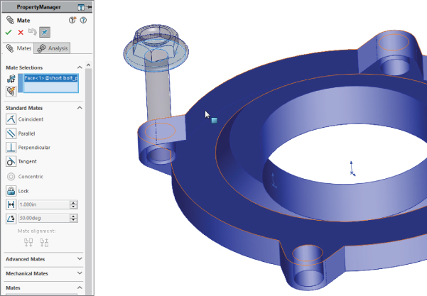
FIGURE 14.4 Using the Alt key to hide faces during mate selection
TEMPORARILY HIDING FACES WHEN SELECTING MATES
Use the Alt key to temporarily hide a face when you need to select an obscured face for mates. Be aware, however, that this keyboard shortcut works only with the following Mate commands:
- Insert Mates
- Edit Mates
- Copy With Mates
- Mated Entities
The components must be displayed in Shaded or Shaded With Edges modes.
After you select a mate, the hidden faces become visible.
To temporarily hide a face:
- Click Mate (Assembly toolbar) or select Insert ➢ Mate.
- With focus in the graphics area, hover over a face and press Alt. The face will be temporarily hidden.
- To show the temporarily hidden face, press Shift+Alt.
- To show all temporarily hidden faces in a semitransparent state, press Ctrl+Shift+Alt.
USING MULTIPLE MATE MODE
![]() Multiple Mate mode enables you to select one face in order to mate multiple parts to it. Figure 14.5 shows the interface for this mode, which you can toggle to from the Mate PropertyManager interface. The Multiple Mate mode icon looks like a paper clip with a lightning bolt running through it. This function works only with the Standard Mate types, not with any of the Advanced mates, which are discussed later in this chapter.
Multiple Mate mode enables you to select one face in order to mate multiple parts to it. Figure 14.5 shows the interface for this mode, which you can toggle to from the Mate PropertyManager interface. The Multiple Mate mode icon looks like a paper clip with a lightning bolt running through it. This function works only with the Standard Mate types, not with any of the Advanced mates, which are discussed later in this chapter.
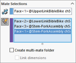
FIGURE 14.5 The Multiple Mate mode interface
You can tell the software to automatically create a special folder for all the multiple mates by selecting the Create Multi-Mate Folder check box in the Mate Selections PropertyManager. You can also automatically link the values for distance and angle mates with link values by selecting the Link Dimensions check box. When you use the Link Dimensions check box, distance or angle values for mates made in Multiple Mate mode will be set equal with link values.
If you're a fan of preselection for mates (a technique sometimes used with mate macros), Multiple Mate mode is induced by preselecting three cylindrical faces or five planar faces. When you select three planar faces, Symetrical Mate mode is induced. With four planar faces or a cylindrical or conical face selected along with two planar faces, Width Mate mode is activated.
Taking Advantage of SmartMates
SmartMates are mates that you can create automatically by dragging one part onto another without invoking the Mate command. There are three different methods that you can use to apply SmartMates:
- Alt+dragging the part
- Dragging the part from one window to another
- Using Mate references
ALT+DRAGGING A SMARTMATE
Probably the easiest way to create a SmartMate quickly is by Alt+dragging. One, two, or even three mates can be applied at once by holding down the Alt key while dragging a face or edge from one part onto a face or edge on another part.
When you are dragging a part while pressing the Alt key, the part is made transparent to enable you to see other part faces to which you may want to mate it. A special cursor appears when a SmartMate is about to be applied. Figure 14.6 shows the cursors that appear for adding Concentric and Coincident mates.

FIGURE 14.6 Applying a SmartMate
When you drop the face or edge onto the mating face or edge to complete the mate, you must use the pop-up Mate toolbar to accept or alter the mate. In the examples in Figure 14.6, a face is being dragged onto another face. However, you can also drag edges and vertices. Mates are limited to being either Coincident or Concentric.
The Peg-in-Hole mate is the combination of a Concentric mate and a Coincident mate. This is the type of mate that is created between a screw and a hole, and it's the result of Alt+dragging a circular edge onto a circular edge. When the circular edges are created by the intersection of a cylindrical face and a flat face, the Concentric mate goes between the two cylindrical faces, and the Coincident mate goes between the flat faces. The Peg-in-Hole mate is illustrated in Figure 14.7. The top two images show the state of the parts before the SmartMate. The image in the lower left shows the SmartMate orienting the part in the wrong way so the two parts interfere. In the image in the lower right, the part to which the SmartMate is applied has been reoriented by the Tab being pressed before the SmartMate is accepted by the part being dropped.
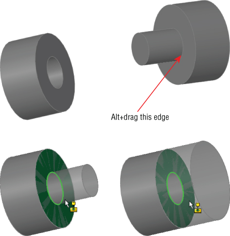
FIGURE 14.7 Using the SmartMate to create the Peg-in-Hole mate combination
You can also Alt+drag a SmartMate to mate origins and coordinate systems. When you Alt+drag one origin onto another, you get the special cursor shown to the left, and when you release the mouse button, the pop-up option box shown in Figure 14.8 appears. If you only want the origin points mated Coincident, turn off the Align Axes option. With the Align Axes option on, the origin points will be Coincident, and the X, Y, and Z directions will be parallel to the same directions in the counterpart origin.
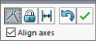
FIGURE 14.8 Using the Align Axes option on the pop-up option box for origin-to-origin SmartMates
DRAGGING BETWEEN WINDOWS
You can simply Ctrl+drag a face of the part to the face of another part in a different SolidWorks window. It is probably most useful to tile windows before creating this kind of SmartMate. Be aware that the Tab functionality changes where three mates are applied simultaneously and a flange mating is created.
USING MATE REFERENCES
Mate references are model faces, edges, or vertices that are preselected and used in a SmartMate-like fashion when you drag a part in from Windows Explorer or from a library window. Mate references are discussed in Chapter 18, “Using Libraries, Assembly Features, and the Hole Wizard,” in the course of discussing library parts. They are a great way to automate common mates with commonly used parts, such as library parts.
Using the Component Preview Window
![]() The Component Preview window splits the display, and opens up to the right of the main graphics window. It allows you to inspect, rotate, zoom, select, and perform other tasks. To open the window, click on a component in an assembly, and use the Preview Component tool in the context menu, or through the drop-down menu under Tools ➢ Component ➢ Preview Window. The display of the component in the main graphics window turns transparent. You can select from the main window and the Preview window for mate selections, for example. When the Preview window is open, a small toolbar is displayed with an Exit Preview button, as shown in Figure 14.9.
The Component Preview window splits the display, and opens up to the right of the main graphics window. It allows you to inspect, rotate, zoom, select, and perform other tasks. To open the window, click on a component in an assembly, and use the Preview Component tool in the context menu, or through the drop-down menu under Tools ➢ Component ➢ Preview Window. The display of the component in the main graphics window turns transparent. You can select from the main window and the Preview window for mate selections, for example. When the Preview window is open, a small toolbar is displayed with an Exit Preview button, as shown in Figure 14.9.
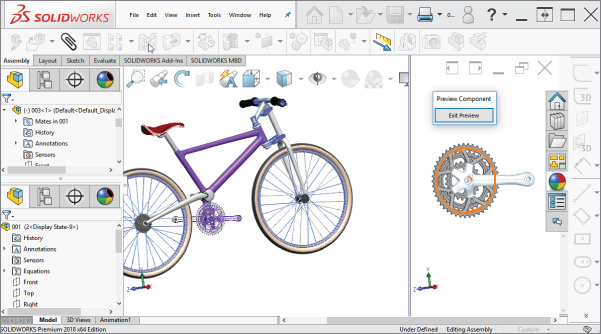
FIGURE 14.9 The Component Preview window is shown to the right.
Using Copy With Mates
![]() Copy With Mates enables you to copy a component from one instance that is mated in place to multiple instances, also mated in place. This is not a pattern; it is more of a shortcut for inserting and mating in place one component multiple times. The time it saves you is in re-creating all the mates and making copies of the component. Remember, a component can be a single part or a subassembly.
Copy With Mates enables you to copy a component from one instance that is mated in place to multiple instances, also mated in place. This is not a pattern; it is more of a shortcut for inserting and mating in place one component multiple times. The time it saves you is in re-creating all the mates and making copies of the component. Remember, a component can be a single part or a subassembly.
The Copy With Mates icon can be found on the RMB menu and on the main Assembly toolbar, although it may not be there by default.
To use the Copy With Mates tool, you must start with a component mated in place. The workflow for Copy With Mates is as follows:
- Start with the component you want to copy mated to another part.
- RMB on the component to copy, and select Copy With Mates.
- In the Copy With Mates PropertyManager, make sure the component to be copied is selected, and then click the right arrow to move to the next step
- Note that the second page of the PropertyManager contains the mates associated with the selected part to be copied, as shown in Figure 14.10.

FIGURE 14.10 Using Copy With Mates to place bolts in holes
- If a face will be selected for multiple mates, check the Repeat box and select the face—for example, a single face to which several bolt heads will mate.
- Select other faces that mate to the copied part, clicking the green check mark after each selection to place the copied part.
You can practice with the Copy with Mates.sldasm assembly from the downloaded materials for this chapter.
Mating with Macros
If you are just applying simple mates, and you’d prefer not to have to deal with all the the confirmations and extra mouse-clicks just to open and close windows, you may want to use macros to mate parts. Macros won't give you the same flexibility; but for simple and predictable mates, they will greatly increase your speed. You must have the parts ready to go when you press the Macro button, or you will create the wrong mate.
You can find macros for Coincident, Concentric, Parallel, Perpendicular, and Tangent mates in the download material for this chapter. For example, to use the Concentric macro, you need to pre-position the parts so they are within 90 degrees of the proper alignment, have one of the parts mated in place such that only one part will move, select the two cylindrical faces, and then run the macro. Ideally, the macro should be connected to a hotkey, so the workflow for this process will be extraordinarily fast. You can click one face, click the other face, and press the hotkey—and the parts will fly together.
Like SmartMates, macros work best for the simpler mate types where you do not need to select any options. The workflow with macros can be very fast, but you must have the parts pre-positioned and be very sure of what you want and what you will get.
Mating for Motion
Dynamic Assembly Motion is a powerful tool for visualizing the motion of mechanisms in SolidWorks. It works best if there is a single open degree of freedom. Assemblies with more open degrees of freedom can do some unexpected things when you try to move them. If there are multiple possible positions, the parts could jump between those positions. If the assembly has parts with unrelated open degrees of freedom, such as fasteners not constrained rotationally on an articulating arm, you may have some difficulty getting the motion you want.
Keep in mind that not all assemblies can function in multiple roles. For example, if you are trying to use a single assembly for an accurate BOM drawing, an exploded view, Dynamic Assembly Motion, setting up in-context references, and a rendering, you may find that even if you are using configurations (covered in Chapter 8, “Selecting Secondary Features”) to divide the types, they still might interfere with one another.
For these reasons, you may want to consider separate assemblies for types of data that are most likely to interfere with other purposes, such as anything to do with moving parts around—Dynamic Assembly Motion, animation, rendering, or others.
Another question you need to ask yourself is whether the Dynamic Assembly Motion is actually necessary. Often, people set it up just because they can, and they may have unnecessary difficulties. For example, parts with in-context references should not have motion between the parts involved. If a referenced part moves, a hole or boss on the referencing part may also move. This sort of thing can be managed, but it requires discipline, and there is an element of risk to the integrity of your data if an untrained or forgetful user gains access to it.
Analyzing Degree of Freedom
When working with motion in SolidWorks, you need to be comfortable with the concept of degrees of freedom. When inserted into an assembly, each component after the first one inserted (which is fixed in place) begins with six degrees of freedom:
- Translation in X (tX)
- Translation in Y (tY)
- Translation in Z (tZ)
- Rotation about X (rX)
- Rotation about Y (rY)
- Rotation about Z (rZ)
When applying mates, and especially when troubleshooting motion or over-definition problems, you must look at how each mate translates into degrees of freedom being tied down. For example, a Coincident mate, planar face to planar face, ties down one translation degree of freedom (in the direction perpendicular to the faces) and two rotational degrees of freedom (about directions which lie in the plane of the faces). What remains are two translational degrees of freedom in the plane of the faces and one rotational degree of freedom about an axis perpendicular to the planar faces.
A point-to-point Coincident mate ties down three translational degrees of freedom, and the part can only rotate.
An edge-to-edge Coincident mate ties down two translational and two rotational degrees of freedom. As a result, a part that you mate in this way can only slide along the mated edge and rotate around the mated edge.
Something to be careful about is that a degree-of-freedom analysis frequently predicts an over-defined mate scenario when SolidWorks does not in fact display any errors or warnings. For example, if one block is mated to another with the simple case of three face-to-face Coincident mates, and each Coincident mate ties down one translational and two rotational degrees of freedom, then the mating scenario ties down nine degrees of freedom, so the part is over-constrained by three rotational degrees of freedom. However, SolidWorks has lots of forgiveness built in, so it commonly allows situations like this, where parts are severely over-constrained. When troubleshooting any over-constrained situation, you should not take this forgiveness for granted. If SolidWorks reports an assembly as over-constrained and the reason is not intuitively obvious, try reducing some of the degrees of freedom constrained. For example, instead of making two faces coincident, consider making them simply parallel or mating a point to a face instead of two faces.
Setting Up Successful Motion
The best bet for creating motion in a SolidWorks assembly is to leave open a single degree of freedom. This means that there is only one way the part can move: back and forth, by translation or rotation. Computers in general do not respond well to ambiguity. Dragging an item that might move in several ways is more likely to cause jerky or hesitant motion.
A good example of this kind of problem with motion can be found in one of the sample assemblies that installs with SolidWorks. This example is included in the download material for your convenience and is shown in Figure 14.11. The filename for the assembly is Plunger.sldasm.
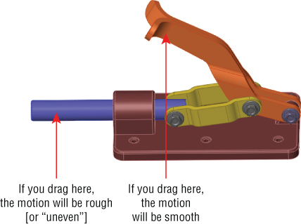
FIGURE 14.11 An assembly displaying the best bet for motion
If you drag the assembly parts from the location shown in Figure 14.11, the performance varies. This is because when you drag the handle parts, for every position of the handle, there is only one solution for the rest of the parts. However, when you drag the plunger bar, for every position of the plunger bar, there are two possible positions for both the links and the handle (one possibility is as shown, and the other would be with the handle interfering with the base of the assembly). This kind of ambiguity causes problems in SolidWorks assemblies such as assemblies that have open degrees of freedom but will not move or move only in a jerky fashion.
Another example of difficulties related to open degrees of freedom and motion is shown in Figure 14.12. The grippers at the end of the arm move when the rest of the arm moves, but the grippers cannot be independently controlled by dragging. To fix this problem, you may want to use the Fix/Float option (available through the RMB menu) or use configurations with mates suppressed or unsuppressed. Fix the part that you want to remain stationary closest to the part you want to move. Remember to float the part when you are finished. Also, be aware that fixing a part may over-define some mates. You can open this assembly from the download materials in the filename called Robot Assembly.sldasm.
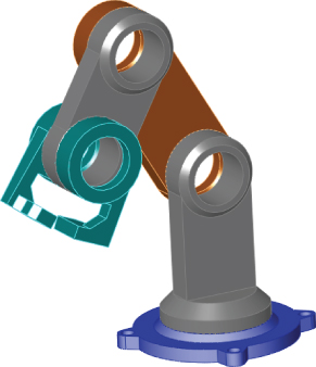
FIGURE 14.12 A robot arm assembly with degree-of-freedom conflicts
Sometimes dragging parts more slowly can help you get the results you expect more easily. Also, moving parts in a more controlled manner—for example, using Move With Triad or Move Along XYZ—can help the software resolve ambiguity.
Using Reference Entities
![]() Reference entities are particularly useful in Angle mates. The best reference entity is a plane or face perpendicular to both of the angled entities. You can think of this like a section plane that defines the angle.
Reference entities are particularly useful in Angle mates. The best reference entity is a plane or face perpendicular to both of the angled entities. You can think of this like a section plane that defines the angle.
SolidWorks never really mentions it, but when you place (or measure) an angle between two faces, it takes the minimum angle; but depending on how you measure the angle, there are infinite options. This sometimes leads to confusion for users and ambiguity for the software.
The easiest way to use this function is to click the Auto Fill Reference Entity button, to the left of the box in the PropertyManager, as shown in Figure 14.13. SolidWorks will select something appropriate for you.

FIGURE 14.13 Using Reference Entity and Dimension Selector
The Dimension Selector is the disk under the cursor in Figure 14.13. The disk is broken into blue and yellow quandrants at the angle pivot axis.
Working with Advanced and Mechanical Mate Types
Advanced and Mechanical mate types greatly expand the number of ways you can put parts together into assemblies and the kinds of motion you can create. Advanced mate types include Symmetric, Width, Path Mate, Linear/Linear Coupler, and Limit. Mechanical mate types include Cam, Hinge, Gear, Rack and Pinion, Screw, and Universal Joint. You can access Advanced and Mechanical mates by expanding the corresponding panels on the Mate PropertyManager (refer to Figure 14.1).
![]() If you understand sketch relations, the standard mate relations fall into place easily. One exception is the Lock mate. Lock is different from Fix, which pins a part to the background. The Lock mate locks two parts to one another, so they always maintain the same relationship to one another, regardless of how they move with respect to other parts. This section goes into some detail about the Advanced and Mechanical mates, with a brief example of each.
If you understand sketch relations, the standard mate relations fall into place easily. One exception is the Lock mate. Lock is different from Fix, which pins a part to the background. The Lock mate locks two parts to one another, so they always maintain the same relationship to one another, regardless of how they move with respect to other parts. This section goes into some detail about the Advanced and Mechanical mates, with a brief example of each.
Profile Center Mate
![]() The Profile Center mate aligns the center-of-area of two selected faces (or sketches) for rectangular, regular polygons, and circular shapes. For example, a rectangular face and a circular sketch will mate, but if you substitute a rectangular or a “+” or “T” shape, you'll get a warning message “Selected entity is not valid for current mate type.” It also accepts inner holes in the face, chamfers, and fillets. This is demonstrated in Figure 14.14.
The Profile Center mate aligns the center-of-area of two selected faces (or sketches) for rectangular, regular polygons, and circular shapes. For example, a rectangular face and a circular sketch will mate, but if you substitute a rectangular or a “+” or “T” shape, you'll get a warning message “Selected entity is not valid for current mate type.” It also accepts inner holes in the face, chamfers, and fillets. This is demonstrated in Figure 14.14.
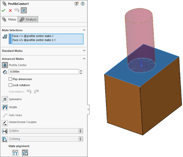
FIGURE 14.14 Setting up a Profile Center mate
You get the options to offset the selected faces, lock rotation, or select the orientation.
This mate type is still new; you can be forgiven for hoping that SolidWorks might in the future include other profile shapes in addition to rectangular and circular. (Hint: use the Enhancement Request process: https://forum.solidworks.com/thread/39406
Symmetric Mate
![]() The Symmetric mate works much like the Symmetry relation in sketches, except that a plane is used as the plane of symmetry instead of a construction line. Figure 14.15 shows a Symmetric mate being applied to the gripper jaws. The Symmetric mate is listed in the Advanced Mates pane of the Mate PropertyManager.
The Symmetric mate works much like the Symmetry relation in sketches, except that a plane is used as the plane of symmetry instead of a construction line. Figure 14.15 shows a Symmetric mate being applied to the gripper jaws. The Symmetric mate is listed in the Advanced Mates pane of the Mate PropertyManager.

FIGURE 14.15 Applying a Symmetric mate
Cam Mate
![]() The Cam mate creates a special instance of either the Coincident or Tangent mate. Four conditions exist with the Cam mate:
The Cam mate creates a special instance of either the Coincident or Tangent mate. Four conditions exist with the Cam mate:
- Coincident: The vertex on the follower mated to a cam that is created from a single closed-loop face (spline, circle, and ellipse).
- Tangent: The cylindrical or planar face mated to a cam that is created from a single closed-loop face.
- CamMateCoincident: The vertex on the follower mated to a cam that is created from multiple faces. This condition enables the follower to go all the way around the cam, without stopping at the broken faces or following the extension of a single face.
- CamMateTangent: The cylindrical or planar face mated to a cam that is created from multiple faces. This condition enables the follower to go all the way around the cam, without stopping at the broken faces or following the extension of a single face.
Figure 14.16 shows a multi-face cam setup, along with the Cam Mate interface. The example files are available from the download material for this chapter in the file named Cam.sldasm.
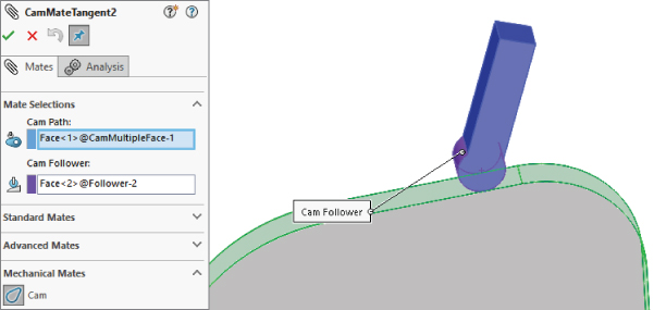
FIGURE 14.16 Using Cam mates
If you open the assemblies and spin the cam plate, you will notice that in both cases, the flat follower does not work very well. In fact, in the single-face cam assembly, it does not work at all, because a planar face is considered an infinite plane for the purpose of mating. For more information, take a look at https://forum.solidworks.com/thread/203350.
Width Mate
![]() The Width mate is often used as a replacement for the Symmetric mate in situations where parts are modeled with some tolerance and have a gap rather than touching face to face. The Width mate requires two pairs of faces to be selected, and it works particularly well when a part must be spaced evenly (or at some percentage to one side) between two faces and there is no mid-plane—for example, when a square key is placed in a square keyway that is somewhat larger than the key. Dovetail keyways are another good application for this mate. If a mid-plane is available, the Symmetric mate may be a better option—or at least a faster one to mate, given that the Symmetric mate requires only two faces and a plane. Figure 14.17 shows a good application for a Width mate as well as the PropertyManager interface for the mate.
The Width mate is often used as a replacement for the Symmetric mate in situations where parts are modeled with some tolerance and have a gap rather than touching face to face. The Width mate requires two pairs of faces to be selected, and it works particularly well when a part must be spaced evenly (or at some percentage to one side) between two faces and there is no mid-plane—for example, when a square key is placed in a square keyway that is somewhat larger than the key. Dovetail keyways are another good application for this mate. If a mid-plane is available, the Symmetric mate may be a better option—or at least a faster one to mate, given that the Symmetric mate requires only two faces and a plane. Figure 14.17 shows a good application for a Width mate as well as the PropertyManager interface for the mate.
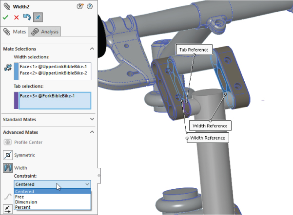
FIGURE 14.17 Centering one part on others with a Width mate
Gear Mate
![]() The Gear mate enables you to establish gear type relations between parts without making the parts physically mesh. You can also apply gear ratios and directions without physical connections, so you can have a shaft in and a shaft out of a black-box transmission without requiring the detail of the gear profiles. You can open the assembly shown in Figure 14.18 from the download material in the file named
The Gear mate enables you to establish gear type relations between parts without making the parts physically mesh. You can also apply gear ratios and directions without physical connections, so you can have a shaft in and a shaft out of a black-box transmission without requiring the detail of the gear profiles. You can open the assembly shown in Figure 14.18 from the download material in the file named Gear Mate.sldasm. To see the effect of the mate, open the assembly and rotate the parts. Then edit the mate, and change the ratio and direction. The selection for the Gear mate is just two cylindrical faces or circular edges. Sketches of pitch diameters are also used.
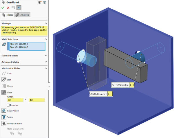
FIGURE 14.18 Applying a Gear mate
Rack and Pinion Mate
![]() The Rack and Pinion mate takes rotational motion of one part and turns it into translational motion for a second part. Again, the parts do not need to be physically connected and can be simple representations of the actual geometry that is needed to drive the motion in the real world. Figure 14.19 shows an assembly that uses the Rack and Pinion mate. You can find this assembly in the download material with the filename
The Rack and Pinion mate takes rotational motion of one part and turns it into translational motion for a second part. Again, the parts do not need to be physically connected and can be simple representations of the actual geometry that is needed to drive the motion in the real world. Figure 14.19 shows an assembly that uses the Rack and Pinion mate. You can find this assembly in the download material with the filename RackPinionMate.sldasm.
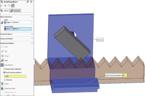
FIGURE 14.19 Applying a Rack and Pinion mate
Limit Mates
![]() You can apply limits to Distance and Angle mates in order to allow the parts to move within a certain range of values. Figure 14.20 shows the PropertyManager interface for the Limit Angle mate. Limit mates accept zero and negative values that are not normally accepted for dimensions in SolidWorks. When used properly, the Limit mate can be an extremely powerful tool for creating more realistic motion in assemblies.
You can apply limits to Distance and Angle mates in order to allow the parts to move within a certain range of values. Figure 14.20 shows the PropertyManager interface for the Limit Angle mate. Limit mates accept zero and negative values that are not normally accepted for dimensions in SolidWorks. When used properly, the Limit mate can be an extremely powerful tool for creating more realistic motion in assemblies.

FIGURE 14.20 The LimitAngle PropertyManager
In the download material for this chapter, open the assembly named Robot Limit Mate.sldasm. Drag the Robot Tower part. Notice that it rotates only within a limited angle. LimitAngle2 is the mate that is driving this motion.
Screw Mate
![]() The Screw mate functions just the way the name suggests. For every revolution of a part relative to another part, the part moves in a linear direction by a specified amount. This mate requires two cylindrical faces and a pitch value, as shown in Figure 14.21.
The Screw mate functions just the way the name suggests. For every revolution of a part relative to another part, the part moves in a linear direction by a specified amount. This mate requires two cylindrical faces and a pitch value, as shown in Figure 14.21.
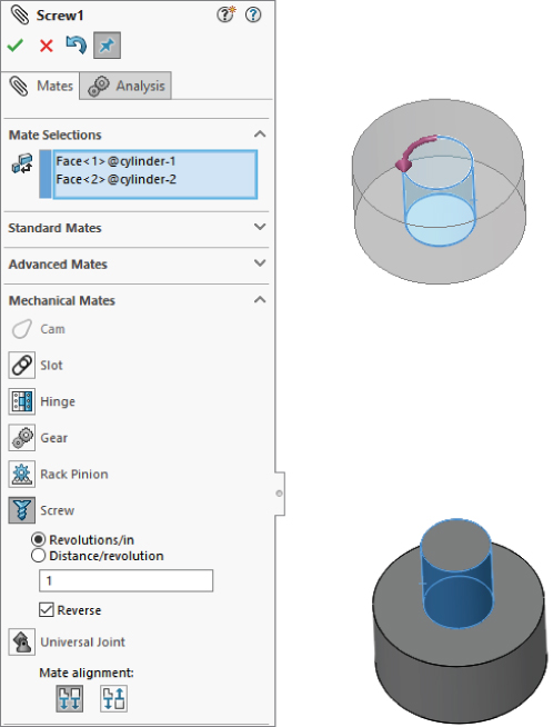
FIGURE 14.21 Setting up a Screw mate
Screw mates can be handy for lead screw animations. Although they are not recommended general modeling; however, if you are working with animations, they are a fantastic addition to the mate toolbox.
Path Mate
![]() The Path mate is the one that makes complex barrel-cam motion possible, as well as other types of path-driven motion. Another application for this mate type beyond barrel cams is for the motion of a camera in a fly-through animation. The Path mate requires a point or vertex on one part and a curve selection on a second part. If the path selection is not just a single sketch or curve entity, it requires the use of the SelectionManager, which enables you to select multiple end-to-end entities to form closed or open paths. Figure 14.22 shows the setup for a Path mate. The
The Path mate is the one that makes complex barrel-cam motion possible, as well as other types of path-driven motion. Another application for this mate type beyond barrel cams is for the motion of a camera in a fly-through animation. The Path mate requires a point or vertex on one part and a curve selection on a second part. If the path selection is not just a single sketch or curve entity, it requires the use of the SelectionManager, which enables you to select multiple end-to-end entities to form closed or open paths. Figure 14.22 shows the setup for a Path mate. The Barrel Cam.sldasm file from the download material demonstrates the selections necessary to make this work.

FIGURE 14.22 Setting up a Path mate
The Path Mate includes some controls for keeping the follower properly oriented. One of these is the Roll Control, which enables you to specify an Up vector. The second of these is the Pitch/Yaw Control, which can be free, or controlled by the path.
You may find that this works better for controlled motion using Animation or motors than for simple dynamic assembly motion driven by the mouse.
Linear Coupler Mate
![]() The Linear Coupler mate relates the motion of one part in one direction to another part in either the same or a different direction. It also enables you to apply a ratio between the motions. The directions do not have to be parallel or anti-parallel; they can be at right angles, or at any angle. The mate controls motion only in one direction, so other directions are free to move.
The Linear Coupler mate relates the motion of one part in one direction to another part in either the same or a different direction. It also enables you to apply a ratio between the motions. The directions do not have to be parallel or anti-parallel; they can be at right angles, or at any angle. The mate controls motion only in one direction, so other directions are free to move.
You can use this mate to simulate symmetric motion or geared motion without modeling the rest of the detailed mechanism. Figure 14.23 shows the setup for this mate.

FIGURE 14.23 Setting up a Linear Coupler mate
Hinge Mate
![]() The Hinge mate is just a shortcut for making a Concentric mate and a Coincident mate combined with an Angle and Limit mate, but it does it all in a single feature and a single interface. Figure 14.24 shows the PropertyManager interface for the Hinge mate.
The Hinge mate is just a shortcut for making a Concentric mate and a Coincident mate combined with an Angle and Limit mate, but it does it all in a single feature and a single interface. Figure 14.24 shows the PropertyManager interface for the Hinge mate.
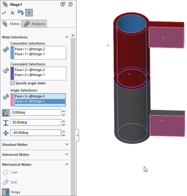
FIGURE 14.24 Setting up a Hinge mate
Belt/Chain
![]() The Belt/Chain assembly feature is not technically a stand-alone mate type, but it uses mates to accomplish its task. You can use the Belt/Chain feature in two ways: to create relationships between sketch blocks and to create relations between parts. This feature also creates a sketch and a solid part representing the belt or chain. You can initiate the Belt/Chain function from a toolbar button on the Assembly toolbar or through the menus by choosing Insert ➢ Assembly Feature ➢ Belt/Chain.
The Belt/Chain assembly feature is not technically a stand-alone mate type, but it uses mates to accomplish its task. You can use the Belt/Chain feature in two ways: to create relationships between sketch blocks and to create relations between parts. This feature also creates a sketch and a solid part representing the belt or chain. You can initiate the Belt/Chain function from a toolbar button on the Assembly toolbar or through the menus by choosing Insert ➢ Assembly Feature ➢ Belt/Chain.
Editing and Troubleshooting
You should become proficient with editing and troubleshooting assembly mates, because you are going to spend a fair amount of time editing assemblies. After you master the techniques, you will be more confident and willing to experiment with assembly changes. Assemblies with errors run more slowly and are unpredictable. Others who use those assemblies may be confused about the assembly design intent if you leave errors in the model. It is always good practice to leave your assemblies error-free for the next user.
Editing Existing Mates
If you are editing just one mate, you can simply right-click it and select Edit Feature (or if you are using context toolbars, left-click it and click the Edit Feature button). Remember that you can find mates in places other than the Mates folder at the bottom of the assembly FeatureManager; most notably, you can find them in folders under the parts they are mating together.
You can also select View Mates from the RMB or LMB menu for a part in an assembly, and for multiple selections of parts. This brings up a small window containing all the mates that involve the selected parts.
Mates are also listed in the breadcrumbs, and you can bring the breadcrumb to your cursor with the D hotkey. Breadcrumbs can be very handy to quickly find items related to whatever you have selected at the time.
You can make several types of changes to mates, including changing the selections, the mate types, and the mate alignment. These types of changes are all shown in Figure 14.25, which displays a mate being edited. The selected faces are highlighted in the graphics window.
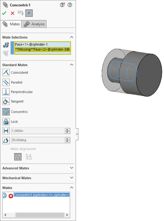
FIGURE 14.25 Editing a mate
To edit multiple mates consecutively without exiting the Mate PropertyManager, you should preselect the mates. Preselected mates are shown in the Mates panel (refer to Figure 14.21). You can switch from editing one mate to another by simply selecting the new mate in the Mates panel. If you select only one mate before clicking Edit Feature, but realize later that you want to edit multiple mates, you can select more mates through the FeatureManager.
When mate entities are lost, the mate appears grayed out. You can repair the missing reference problem by selecting the invalid reference in the Mate Selections window and then selecting the correct item from the graphics window. When multiple mates are missing the same reference, and it is repaired in one of them, SolidWorks gives you the option to replace the new reference in the rest of the broken mates.
A yellow triangle symbol in front of a mate is satisfied, but it is in conflict with another mate that is not satisfied.
To repair the mate shown in Figure 14.25, select the Missing Face entry in the PropertyManager, and then select the correct face in the graphics window using any of the selection options available in SolidWorks. When a missing reference used by multiple mates is repaired, you have the option to repair all the mates using it. Also, it is important to know, that when you attempt to apply a mate that would contradict existing mates, there are three options: cancel the application of the new mate, break the new mate, or break the other mates.
Troubleshooting Assembly Mates
It is best to troubleshoot an assembly mate problem as soon as it appears, not after it has become complicated by other issues. Failed mates also cause performance problems because SolidWorks keeps trying to solve the mates that are in conflict with one another.
Assembly problems often appear to be far larger than they actually are. For example, the entire tree may light up with warnings and error symbols when one extra mate is applied. You can use several approaches to troubleshoot situations like this. For example, you can purposely over-define mates just to locate a leftover mate or a mate that is not supposed to be there.
Two types of symbols may help you distinguish the kinds of errors that are present in different mate features. A yellow triangle that contains an exclamation point is not an error; it is actually more of a warning. It tells you that this mate is in conflict with other mates (this symbol is used for a variety of warnings), but that the mate is still satisfied geometrically. One of the other mates with which it conflicts is probably not valid, so this type of warning is usually accompanied by an actual error symbol where the mate is not satisfied.
A red circle containing an X is a failed mate. This mate is in conflict and is invalid. If it is also a Coincident mate, then the two Coincident entities are not coincident.
To make it easy to find problem mates, if you click on the top-level assembly name in the AssemblyManager, SolidWorks displays all of the mates under warning and error messages, as shown in Figure 14.26.

FIGURE 14.26 SolidWorks shows the mate errors and warnings at the top level.
Troubleshooting Warnings and Errors
SolidWorks distinguishes between errors and warnings. Errors are situations where a condition is not satisfied, such as a Coincident mate where the selected entities are not coincident. Errors are marked with a red symbol. Warnings mark situations where a conflict exists, but otherwise all conditions are met, with a yellow triangle and an exclamation point. For example, both a Coincident and a Perpendicular mate use the same faces. One mate will have an error and the other a warning, because one can be satisfied, but not both.
You can use the following troubleshooting techniques to work with assemblies where errors or warnings exist:
- Last In First Out When a mate is added that causes warning and error signs to appear throughout the design tree, you can usually correct the problem by removing this last mate.
- Single Elimination If you are sure that the last mate added is correct, then you may want to go backward up the tree, starting at the bottom and suppressing individual mates until you find one that causes the warning and error signs to disappear from the tree.
- Single Addition It may be easier to take the opposite approach, by suppressing all but the mates that you are sure of and then gradually unsuppressing mates until the conflict reappears.
- Suppress a Part With all the mates active, try suppressing an individual part to see whether this makes a difference. If it does, then unsuppress the part and look at the mates for that part in the Mates folder under the part.
- MateXpert The MateXpert is an automated routine that creates subsets of groups of conflicting mates. Each subset of mates has one mate that is not satisfied because of the conflict. This may help you to find the cause of the conflict. Figure 14.27 shows the MateXpert interface. You can access the MateXpert from the RMB menu on mates with errors, or through the main menus at Tools ➢ Evaluate.
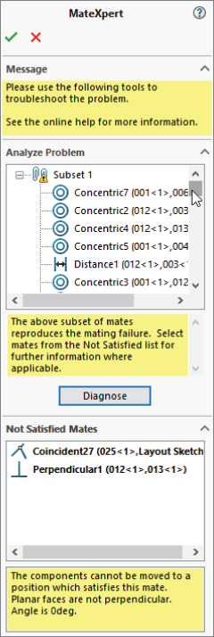
FIGURE 14.27 The MateXpert interface
Examining Mate Options
The Options pane of the Mate PropertyManager is shown in Figure 14.28. These options control actions taken with newly created mates.
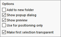
FIGURE 14.28 The Options pane of the Mate PropertyManager
- Add To New Folder puts any newly created mate in its own new folder. When it is turned off, new mates are put at the top level after the last folder.
- Show Popup Dialog shows the pop-up list in Figure 14.2 when a mate is being created. The pop-up list is displayed in the graphics area next to the geometry selections for the mate.
- Show Preview pre-positions the mated parts before exiting the command.
- Use For Positioning Only positions a part but does not apply or remember the mate. Some users select this option often for various applications where they need the part located precisely, but they do not need or want a mate feature in the tree. One example of using this option is to position a part for animations where the part does not move according to a mate.
- Make First Selection Transparent was mentioned earlier in this chapter. It turns the first part you select for the mate transparent to the user and to the cursor, so you can select whatever is behind it.
Reviewing Mate Best Practices
Sometimes, best practice recommendations can contradict one another, and for each best practice recommendation you find, there are likely several specific situations where the recommendation is invalid or even a bad idea. As a result, you should apply the following recommendations carefully. Don't take best practices too seriously, but you should not disregard them altogether. Some companies use best practice recommendations as modeling standards. The less experience your SolidWorks team has, the more you need standards of this sort. Every situation has a different need for best practice—and maybe even a need for a set of rules that are different from the ones laid out here. You can think of this set of mate best practices as a starting point for the discussion at your own company.
- Each assembly should have at least one part that is either fixed or fully mated to the standard planes of the assembly so it cannot move relative to the assembly.
- Use fixed parts sparingly. One part that serves as a “ground” for the assembly should be fixed. Other than that, the parts of imported assemblies are sometimes fixed to keep them from being moved accidentally.
- Do not mate to time-dependent features in the assembly tree, to patterned components, or to in-context features in parts. This can create circular references where the assembly must be rebuilt multiple times to fully resolve the positions of all parts and sketches.
- When possible, mate all parts to the “ground” part. Creating daisy-chain mates (where A mates to B, which mates to C, and so on) forces the mates to be solved in a particular order, which may take more time to solve. If all the mates relate to established assembly references, the mates may be more stable. Chapter 13, “Building Efficient Assemblies,” describes using a skeleton in a part to make sketch and feature relations. You can apply a similar concept in an assembly by mating parts to an assembly sketch.
- When possible, leave part positions fully defined, especially when other geometry is dependent upon the position of parts. Some examples include in-context features, assembly features, or assembly-level reference geometry, which are dependent on part geometry.
- Constraining the rotational degree of freedom for components such as screws, washers, and nuts is usually considered excessive. At times, too many open degrees of freedom may cause problems with complex motion, such as a gripper on the end of a robotic arm. SolidWorks functions well when there is a single, well-defined path between two points; but when there are multiple options, the software may become confused.
- Do not leave errors unresolved in the tree.
- Remember to use subassemblies to break up the number of mates that are solved in the top-level assembly.
- Limit the use of flexible subassemblies.
- Do not mate to entities that may be removed later by suppressing or unsuppressing features, especially edges or faces that are created by features such as fillets. For this reason, it is usually best to wait until parts are complete before you use them to create an assembly, although this is rarely practical.
- Use a degree-of-freedom analysis to prevent mates from becoming over-defined.
- Mate the hardware (nuts, bolts) to the main components, not the other way around. If the hardware is suppressed, the assembly motion should be unaffected.
Tutorial: Mating for Success
In this tutorial, you will put together a model of a robotic arm to better understand some of the mate issues discussed in this chapter. Follow these steps to mate for success:
- Open the part named
Robot Base.sldprtfrom the download website.  In the part document window, click the Make Assembly From Part icon, and click the cursor on the origin of the assembly to place the part origin at the assembly origin. The part is automatically fixed in place.
 Choose Insert ➢ Component ➢ Existing Part/Assembly. Click the Browse button in the PropertyManager, and find the part called
 Robot Tower.sldprt. This part contains a Mate reference to help you mount it to the base. If you bring the cursor near the big circular hole in the base, you can see the preview of the tower snap into place. Click to accept this placement. Figure 14.29 shows this placement in progress. Notice the Rotate context toolbar option and the bar itself in the graphics window. This helps you get the newly placed part oriented correctly. Also notice that the cursor appears as a SmartMate cursor for the Peg-in-Hole mate. When the part is dropped, check the mate list to confirm that a Concentric mate and a Coincident mate have been applied by the Mate reference.
FIGURE 14.29 A Mate reference being used to SmartMate a component
- Open the part with the filename
Robot Arm.sldprt, the default configuration, in its own window, and choose Window ➢ Tile Vertically. The part and the assembly should be open in adjacent windows. - Click the face inside the hole without the chamfer around it in the Arm part, as shown in Figure 14.30. Then drag it into the assembly to the cylindrical face inside the hole at the top of the Robot Tower part. The concentric SmartMate symbol should appear on the cursor.

FIGURE 14.30 Displaying a SmartMate when dragging between windows
- Click the green checkmark icon to accept the Concentric mate. Move the part to test that the mates are correct.
 Click the Mate tool on the Assembly toolbar. Expand the Advanced Mates panel, and click the Width mate.
- In the Width Selections box, select the two inner faces of the Robot Tower part, and in the Tab Selections box, select the outer faces of the Arm part. The selection should look as shown in Figure 14.31.
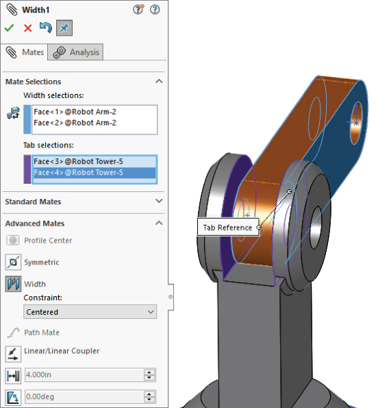
FIGURE 14.31 Creating a Width mate
- Open a Windows Explorer window, and select the following parts:
Robot Arm2andRobot Gripper. Drag these parts into the SolidWorks assembly window, and drop them in a blank space. - Select the chamfered faces of the Arm and Arm2 parts, and create a Coincident mate between them. You can make Coincident mates between conical faces as long as the cones are the same angle. This special case acts like a combination of Concentric and Coincident mates. Figure 14.32 shows the selections and the result.
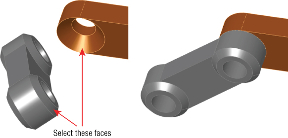
FIGURE 14.32 Making conical faces coincident
- Create a copy of the gripper part so there are two instances of it in the assembly. You can do this by Ctrl+dragging the part within the assembly window with the Mate PropertyManager closed.
- Mate both of the grippers to the Arm2 end using the same mating technique that you used for the previous conical face Coincident part.
- After you have applied these parts, try moving the various joints of the assembly. Notice that it is difficult, if not impossible, to isolate the motion of just a single part. This is because there are too many open degrees of freedom and lots of ambiguity.
- Fix Arm2 to allow you to move the gripper parts as you want. Create a Symmetric mate between the indicated faces of the grippers and the Front plane of the Arm2 part, as shown in Figure 14.33.
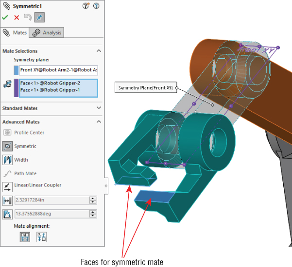
FIGURE 14.33 Creating a Symmetric mate
- Practice making angle mates, suppressing mates, and fixing parts to limit motion.
- Save the assembly and exit the file.
The Bottom Line
A thorough understanding of mates (and their editing and troubleshooting techniques in particular) makes the difference between a real assembly artist and a user who struggles through or avoids certain tasks. Much about mates is not straightforward, but with practice, you can understand and master them. You can put assemblies together quickly, with a focus on rebuild performance and Dynamic Assembly Motion.
Although best practice concepts should not dominate your designs, they are great guidelines from which to start. To avoid making big mistakes, watch out for the pitfalls outlined in page 27, Reviewing Mate Best Practices section in this chapter that summarizes mate best practices to follow.
- Master It SmartMates are a key to putting assemblies together quickly in SolidWorks. Practice using SmartMates in a single assembly window, and also between a part and assembly in tiled windows. Practice using the Tab key to flip the orientation of the mate.
- Master It Make sure you understand the function of mates. Go through a sample assembly and sort through the mates that prevent motion and the mates that enable motion. Put these mates into separate folders.
- Master It Work through several of the specialized mechanical mates and make sure you can use the sample assemblies to re-create the motion. Use the parts from the sample assemblies for each of the mates and reassemble the parts to have the intended motion.