
Chapter 37
Using Imported Geometry and Direct-Editing Techniques
Dealing with geometry imported from other CAD systems is often difficult, particularly in history-based systems. Imports aren't always clean, meaning they often need repairs. Sometimes, you might want to change it. Imported data is often called “dumb geometry” because it has no features. Imported data can be edited using Direct Editing tools and techniques.
The Direct Editing tools in SolidWorks enable you to change a part without having access to the history of features that created the part; however, they do create history-based features in SolidWorks. Direct editing works on both native and imported geometry either by simply moving faces or by editing the geometry directly rather than indirectly through feature definitions or sketches.
This chapter looks at the Import and Export tools available in SolidWorks and the Direct Editing tools that can be used to manipulate imported or native geometry.
Understanding the Basics of Imported Geometry
Geometry that's transferred between CAD packages is called imported geometry. The transfer usually happens through IGES (Initial Graphics Exchange Specification; pronounced eye-jess), STEP (Standard for the Exchange of Product), Parasolid, or ACIS (named for the initials of three people who created the standard: Alan, Charles, and Ian's System) formats. SolidWorks also reads some native CAD data directly. For example, SolidWorks can read data directly from versions of Pro/ENGINEER, Unigraphics/SDRC (NX), Inventor, Solid Edge, CADKEY, and Rhino, as Figure 37.1 shows. In most cases, features aren't transferred between CAD packages. The geometry that you wind up with is called “dumb” geometry because the list of features that the model had in its parent software is no longer there.

FIGURE 37.1 SolidWorks opens neutral format files as well as several native formats.
You can import data in two ways. The most common way is to use the Open dialog box and switch the Files Of Type to an imported file format. The other way is to use the Imported Geometry feature by choosing Insert ➢ Features ➢ Imported Geometry from the menus. The Open dialog box creates a new part with the imported feature at the top of the FeatureManager, as shown in Figure 37.2. Using the Imported Geometry feature enables you to insert imported geometry anywhere you like within the FeatureManager, even after other features have been added.

FIGURE 37.2 Imported geometry comes in without any feature history.
You can use the Data Migration tab in the CommandManager to find tasks that support imported geometry. The tools on this tab are shown in Figure 37.3.

FIGURE 37.3 The SolidWorks Data Migration tab on the CommandManager helps you find Import tools.
Many of these tools aren't directly related to imports but may be frequently used with imported bodies. FeatureWorks is a part of the SolidWorks Professional bundle and is beyond the scope of this book; however, it's mentioned as one possible workflow for editing imported geometry toward the end of this chapter.
Using SolidWorks 3D Interconnect
SolidWorks 3D Interconnect enables you to treat imported documents as (one-directionally inbound) associative to the original native format files. This means that if you import an Autodesk Inventor file using 3D Interconnect, and then change that file in Inventor, you can update the imported geometry in SolidWorks. Changes to the part in SolidWorks cannot be sent back through the link to the original native Inventor part. 3D Interconnect functionality is supported for the following systems:
- CATIA V5:
.CATPart,.CATProductfor V5R8 – 5–6R2016 - Autodesk Inventor:
.iptfor V6 – V2016,.iamfor V11 – V2016 - PTC:
.prt,.prt.*,.asm,.asm.*for Pro/ENGINEER 16 – Creo 3.0 - Solid Edge:
.par,.asm,.psmfor V18 – ST8 - NX software:
.prtfor UG 11 – NX 10
This functionality is turned on by default starting in SolidWorks 2017. You can control the settings for 3D Interconnect at Tools ➢ Options ➢ Import.
When a part is imported using 3D Interconnect, it comes in with the -> symbol that connotes external links. The external link works by first importing the “dumb” body geometry from the native file (much in the way the Parasolid body is stored within a SolidWorks part), and then reimporting the body from a changed file. It is better to get body data directly from the native file than it is to get it from a translated format such as IGES or even STEP—and in my opinion, this is the biggest advantage of using 3D Interconnect.
The claimed associative link is somewhat dubious. Primarily, the SolidWorks imported data is being saved internally as a Parasolid body in a separate SolidWorks part. There is no real link to the native format file in the sense that you are used to native SolidWorks parts being actively open and linked to a SolidWorks assembly.
Secondly, you are able (and have been able for some time) to do this reimport without using 3D Interconnect by simply using the Edit Definition function for an imported body. After all, it is this functionality that SolidWorks is using behind the scenes, automating it somewhat and giving it a fancy name. Whether this is more or less work than using the so-called associative nature of 3D Interconnect is for you to decide.
Again, my opinion is that because some direct modeling CAD packages are able to import data and directly edit that data (and SolidWorks is not able to do that, as you will see later in this chapter), SolidWorks probably felt as if they needed to answer this lack of functionality, even though the answer is predominantly smoke and mirrors.
Anyone with a little practical experience knows that importing data from CATIA can be challenging. Using 3D Interconnect to extract solid body data and convert it to Parasolid is likely the most reliable way to convert CATIA V5 data.
The rest of this chapter is written with the assumption that 3D Interconnect has been disabled. To work through the exercises as intended, I recommend that you turn 3D Interconnect off until you think you need it.
Gaining Experience with Imports
When SolidWorks imports data from another CAD program, the result is an imported feature in the FeatureManager. The example shown in Figure 37.2 is the situation you're typically looking for: the result is a single solid body. Frequently, imports don't come in this clean. When imports start giving you trouble, you'll see errors on a single body, or possibly multiple bodies, or even surface bodies. SolidWorks can address some types of errors automatically, and you can address some manually. From time to time and for various reasons, you might get such a messy part that you just want to try a different method to import it (for example, different import or export settings, or a different file type).
The best way to start to feel comfortable with imported data is to be exposed to a wide range of files—some that work and some that don't. This chapter isn't intended to be a short course on import repair, but repair is certainly part of the reality of working with imported data.
UNDERSTANDING THE RESULTS OF IMPORTS
When you import geometrical data into SolidWorks, you can get several different types of results:
- Single solid body in a part file
- Assembly of multiple parts
- Multiple solid bodies in a part file
- Surface bodies in a part file
- Combination of solid and surface bodies in a part file
When you get an assembly of parts, SolidWorks uses the default template that you have designated in Tools ➢ Options ➢ Default Templates, creates new parts, and saves them to your hard drive automatically.
Some imports also create a report file with the extension *.rpt or *.err. This file includes statistics about the entities and precision of the data, filename, units, the originating system, and some information about errors that occurred during the import.
Figure 37.4 shows the first section of a report written for the import of an IGES file.
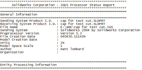
FIGURE 37.4 Report files can help you understand the contents of the imported file.
DEMONSTRATING SOME DATA IMPORT
I'm going to import a few parts that don't come in perfectly and ask you to follow along with the files in the materials you downloaded from the website. This isn't so much a click-by-click tutorial as a “watch over my shoulder” demonstration with commentary.
Starting with a Parasolid import because Parasolids are the fastest and easiest, open the part called Chapter 37 Robot Arm.x_t from the download material for Chapter 37. You can open translated format files in a couple of ways. Many people look for an Import or Translate option in the File menu, but it's not there. You can use the Open command and select Parasolid from the Files Of Type drop-down list, but that's the slow way. I prefer to open a translated file using Windows Explorer, and drag and drop the file onto the SolidWorks window.
After you open the file, you'll notice a couple of things. The first thing that stands out to me is that the model displays in Shaded mode, regardless of how you have the display set. For example, I like to use Shaded With Edges, but imports always set it back to Shaded.
The next thing to notice is the Imported1 feature in the FeatureManager. In this case, the import was clean, so there are no warnings (yellow triangles) or errors (red circles). This isn't always a good indication of the state of the part, though, because some errors that SolidWorks knows about aren't displayed on the Imported Feature icon. To investigate closer, right-click the Imported1 feature and select Import Diagnosis, or click Import Diagnosis from the Evaluate tab of the CommandManager.
In this case, the model really is clean. Running Import Diagnosis is the only way you can really know this. Figure 37.5 shows the FeatureManager, the Import Diagnosis, and the part itself.

FIGURE 37.5 Parasolid imports have the tendency to be fast and trouble free.
Next, open the Parasolid file called badface.x_b. This one also imports without an error or warning on the Import feature, but there's clearly a missing face. It's easier to visualize the separate faces of the part if you change the Display mode to Shaded With Edges. If you examine the part closely, you can see that several faces aren't lined up square with the rest of the part. Notice also that there are small sliver faces. This may be intentional, or it may be part of the problem. Triangular faces and sliver faces (with very sharp corners, usually long and narrow) are often the source of errors in translated parts.
Right-click the Import feature and run the Import Diagnosis; you'll see the faulty face listed. Click the Attempt To Heal All button to fix the faulty face. Figure 37.6 shows the part with the faulty face.
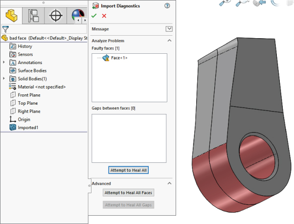
FIGURE 37.6 Three-sided and sliver faces are often the sources of errors with imported parts.
Now open the Pro/ENGINEER file called bad face 2.prt.29. Pro/ENGINEER files often end with version numbers as their extensions. You need to be careful if you see a file that looks like a Pro/ENGINEER file with no version extension. SolidWorks used the *.prt extension for the first couple of years, and it still opens this type of file as a native file. You may still find some of those parts in circulation.
Open the file using the Import Geometry Directly option, switch the display to Shaded With Edges, and run an Import Diagnosis. The part has a bad face. If you click the face in the Faulty Faces list, you can see that the face is next to a small, pointy triangular face, shown in Figure 37.7. The Attempt To Heal All option takes care of it.
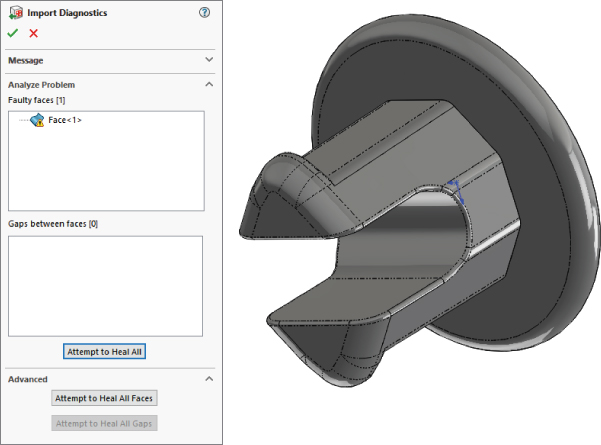
FIGURE 37.7 Importing the same data in different ways can give you different results.
Import the same file, but this time choose the Analyze The Model Completely option. It should tell you that it recognizes 13 out of 13 features. Click the Features button and watch the part rebuild. Notice that this time the part comes up with a feature error. The error is on a fillet. It isn't an accident that the previous error was on a face next to a fillet face.
Notice that the Parasolid parts came up almost immediately, but the Pro/ENGINEER parts take several seconds to process the data. As the imported files become larger and larger and branch into assemblies, this difference in processing time becomes more and more pronounced.
Next is a sheet metal part. Open sheet metal.x_t. Change the display to Shaded With Edges. The part looks good, and Import Diagnosis says that it's okay. Because this is a sheet metal part, and it appears to have a consistent thickness, you'll try to flatten it. Click the Sheet Metal CommandManager tab and click the Insert Bends icon (on the far-right side). Select the big flat face as the face to remain stationary (the top selection box), and click the green checkmark button to accept the result.
The sheet metal features are added to the part, but notice in Figure 37.8 that they have failed. A close inspection of the part reveals that there's a small ledge between the big flat face and the inside bend on both ends. This was probably a modeling error rather than a translation error. You may be able to fix this to make it usable as a sheet metal part; but for imported geometry editing, you'll need to go to the end of this chapter. Here, I cover the results of attempting to repair this model.
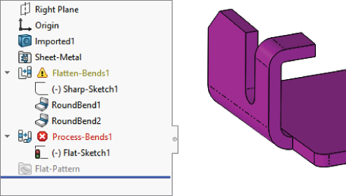
FIGURE 37.8 Very small errors can cause special functionality in SolidWorks not to work. Repairing those errors isn't always straightforward.
The last part I want to show in this “watch over my shoulder” demonstration is a part that I consider to be a complete loss. This is an IGES file that came from an Autodesk Mechanical product. In the download materials, open the file called valve body.igs. This part takes several seconds to import. When it does import, it has 10 surface bodies, dozens of face errors, and some obvious problems with a couple of faces that somehow became out of control. This is one of the reasons so many users do not recommend using IGES files. This type of error is more prevalent with IGES files than other formats. Figure 37.9 shows the FeatureManager and the part on the screen. Again, notice that the locations where the huge problem faces come off the model are pointy triangular faces.
![Left: Import Diagnostics FeatureManager with filled boxes for Faulty Faces [77] and Gaps between faces [50] and highlighted Attempt to Heal All below. Right: 3D illustration of the model with pointy triangular faces.](http://images-20200215.ebookreading.net/2/1/1/9781119300571/9781119300571__mastering-solidworks__9781119300571__images__c37f009.jpg)
FIGURE 37.9 Some parts are simply beyond repair.
Very often you will find that the import results between versions of SolidWorks differ. For example, in SolidWorks 2018, this valve body imports with enough success that you might be able to model over the surface bodies and eventually piece together the original model. Earlier versions didn't get that close.
If you get a part that's this bad, your first move should be to try to get better data from the source. If that isn't available, you'll have an uphill battle trying to make this part work. Automatic healing with the Import Diagnosis isn't going to touch this part. The repair is going to be an exercise in manual surface modeling. If you don't have the patience for that, you could try solid modeling from the reference faces on the part. If you look closely at the interaction of some of the fillets, it won't be a surprise that the translation failed so badly. Many of the fillets are badly hacked together. In addition, if this is a casting, someone is going to need to apply draft to the part, and with all the fillets on it, this part isn't going to lend itself to that very well.
Handling Import Errors
Import errors are usually caused by differences between the exporting and importing CAD software vendors. Some imports are more prone to errors than others. For example, the IGES format is interpreted different ways by different software vendors, so it's very prone to errors.
Another type of error is due to tolerance or accuracy issues. CATIA is notorious for having very large tolerances on exported data. This enables CATIA to work with large data sets more easily, but it means that when the geometry is read into SolidWorks, which typically requires more accurate data, you can see a lot of errors. The fact that the CATIA-to-SolidWorks translation is one of the most problematic in the CAD industry seems odd because SolidWorks and CATIA are both owned by Dassault Systèmes, but the difficulties have persisted for more than a decade, so it isn't a technological difficulty; it's a business decision.
REPAIRING IMPORT ERRORS AUTOMATICALLY
SolidWorks has a tool called Import Diagnostics. Import Diagnostics can run automatically or manually to find the errors in imported data and to make repairs if possible. You can access Import Diagnostics by right-clicking an imported feature in the FeatureManager, as long as there are no native SolidWorks features that follow the imported feature. Figure 37.10 shows typical results from a faulty import.
![Left: Import Diagnostics FeatureManager with filled boxes for Faulty Faces [5] and Gaps between faces [5]. Right: 3D illustration of the result from a faulty import depicted by a circular shape bounded in a rectangle.](http://images-20200215.ebookreading.net/2/1/1/9781119300571/9781119300571__mastering-solidworks__9781119300571__images__c37f010.jpg)
FIGURE 37.10 Import Diagnostics helps you find and repair errors in imported data.
Sometimes, the errors that Import Diagnostics finds are things you can see, such as missing faces, and sometimes, they are things you can't see, like the edges of a face that don't intersect or inconsistent face normals. When errors can be found and repaired by Import Diagnostics, that's the best way to go.
REPAIRING IMPORT ERRORS MANUALLY
Some errors are so big that the Import Diagnostics cannot fix them. An example of this type of error is when a face is missing altogether from the imported data. When something like this happens, the only thing you can do is resort to surface modeling. If the import leaves you with surface bodies, and it cannot repair them automatically, you must be able to remove the bad faces and replace them with new faces that you construct. This is all about using Surface tools to create the new face, extending and possibly trimming the new face to fit into the gap caused by the bad face or faces, and then knitting everything together back into a solid. This may be an oversimplification of the workflow for manual import repair, but it's essentially the big-picture steps that you must go through to get the task done.
Some models are so bad that you can't fix them, or they wouldn't be worth your time to fix. If automatic repairs don't work and simple manual repairs don't work, the next thing to do is to go back to the source of the file and ask for better data.
If you get bad data, you don't have access to the source, and automatic and manual errors prevent you from using the data, then the next best thing is to rebuild the part using the error-filled data as a reference. This is never a pretty thing, but if you really need the data to be clean, and there is no other way, this is what you need to do.
You can take measurements in one file and build a new part in another file, build one file in the context of an assembly directly over the problem file, or even rebuild it as a multibody part.
TRICKING DATA INTO WORKING
Occasionally, you can employ tricks to heal problem imports. Simply saving out of SolidWorks as Parasolid and reading back in repeatedly can sometimes heal troublesome imported geometry. I frequently use Rhino to import problem files and then export from Rhino as a Parasolid. Rhino is an inexpensive surfacing application. You can read more about it at www.rhino3d.com. You can download and install a trial version that allows you to save 25 times. Rhino works great as a translator because it reads and writes many file types that SolidWorks doesn't read. Sometimes, when I get a very bad IGES file, I read it into Rhino, save it out as Parasolid, and then read the Parasolid into SolidWorks. Sometimes, this repairs the data to the point that SolidWorks can deal with it more effectively.
This isn't to say that Rhino is a better file translator than SolidWorks, because this workaround doesn't always improve things. It's sometimes effective, and because it's free, the only thing that trying it costs you is time.
ENSURING GOOD DATA
If you can't get a SolidWorks file from someone who needs to send you data, the type of translation file that you do get has a huge influence on the likelihood that your translation will be successful. Ask for data in this order:
- Parasolid (including native formats that use Parasolid, such as NX, Unigraphics, and Solid Edge). Parasolid can come in text format (
*.x_t) or binary format (*.x_b). You may also see file extensions such as.xmttxtfrom older versions of Unigraphics. Of these, the binaries are smaller, but the text files have WordPad readable and editable headers that can be useful in various situations, such as correcting units or part scaling, as well as telling what the parent CAD program was. - STEP (AP 214 or AP 203). The AP stands for application protocol. Most mechanical CAD programs use these two protocols, which were developed for automotive and configuration-controlled design (read more at
www.steptools.com/library/standard/step_2.html). - ACIS. ACIS creates
*.satfiles. *.VDAFS,*.VDA (). This is a German automotive geometry transfer format.- IGES. Because of the age and lack of clear definition in the IGES format, little about it is truly standard anymore, and many geometry-creation-software packages export data that SolidWorks cannot read correctly. Although this format is a standard for old-timers, it's one you probably want to avoid unless you're getting data from someone you know will give you something usable.
Another advantage of the Parasolid data is that SolidWorks reads it so quickly. A large IGES or STEP file can take minutes to read in, where SolidWorks can read equivalent Parasolid data in a couple of seconds. After the data is read into SolidWorks, it should all be the same, with no difference between data from Parasolid and any other source, because it's all converted to Parasolid to be stored inside the SolidWorks file. Parasolid reads in very quickly, so it saves time.
Whether or not the data you receive is of value to you depends in part on what you want to do with it. If your data is for a visual representation and not a CAD-accurate NURBS (Non-Uniform Rational B-Spline) model, you may be able to accept a wider range of data types. If you're looking for manufacturing quality data, dealing with some formats is simply not worth your time. The following file types are mesh data that SolidWorks can read and are useful for visual data, but useless for clean NURBS data:
*.stl: Stereolithography, typically used for rapid prototypes*.vrml: Virtual reality markup language, typically used for games; an old format that allowed color to be transmitted with the mesh geometry*.cgr: CATIA graphics
Converting Point Cloud Data
One of the most common import questions is how to import data from file formats such as *.obj or *.3ds, among others. These file types are mesh files, which means they are simply point cloud data. SolidWorks and most other CAD programs create geometry that's based on NURBS data, where the surfaces are represented by very accurate mathematics. Mesh data is represented by points in space, which is much faster to work with because it's similar to the data used by graphics cards and drivers to display curvy shapes. Mesh data is used by Hollywood, video game developers, and computer graphics studios; NURBS data is used in engineering and manufacturing. It's easy to convert NURBS to mesh, but it is more difficult to convert mesh to NURBS. The mesh-to-NURBS conversion can be done, but complex software and specialized expertise is needed for it to happen correctly.
Understanding the Traditional Role of Direct Editing Tools
Traditionally, direct-editing CAD software has lived by the rule that how you create geometry shouldn't affect how you edit the geometry. Therefore, direct-editing CAD packages still use functions like Extrude and Revolve to build parts, but they won't return to those functions to edit the part; instead, they directly manipulate faces of the part by moving, offsetting, and rotating.
CAD software that depends on Direct Editing tools has existed for a long time. Some direct-editing CAD products have appeared on the scene and have renewed an interest in direct-editing techniques. Until this recent resurgence, the direct-editing programs were seen as old-fashioned and inferior to parametric history-based programs.
One way to think of direct editing is that it leaves the intelligence in the software. In history-based techniques, you put the intelligence in the data.
Technically, what SolidWorks does when it works with imported featureless geometry is not direct editing, because it leaves a trail of history-based features behind, which is very much opposed to most of the benefits you get from true Direct Editing tools, such as lack of rebuild time, lack of a history tree, and so on. If you want to research direct editing in the form of synchronous technology developed by Siemens PLM, you can find a free, short book that I wrote on that topic at https://www.plm.automation.siemens.com/en/campaigns/single_topic.cfm?Component=247520&ComponentTemplate=186312
History-based modelers are still popular with users who design things. There must be more to this story, because the direct-editing scheme has some weaknesses. There are situations in which certain edits cannot be made in a straightforward way or reversing a set of edits doesn't result in the original configuration.
This background information is important as a part of the overall discussion of the place these tools have in the SolidWorks software. Adding Direct Editing tools to SolidWorks isn't an earth-shattering change, but it's of secondary importance. The Direct Editing tools in SolidWorks are a bit odd because direct editing stands as an opposite to history-based techniques. In SolidWorks, the Direct Editing tools are within history-based software. You don't really get all of the available benefit from direct editing when it's done inside of the history-based method.
Understanding the Strengths and Limitations of Direct Editing Tools in SolidWorks
Some of the selling points for the direct-editing CAD tools are that you don't have to worry about how a part was made (you just make the changes you want to make) and that feature trees with “history” always include feature rebuilds (and users tend to complain about these rebuilds taking a long time, especially for large parts and assemblies).
Without a doubt, grappling with feature order and feature rebuild times are problems that SolidWorks users face daily and often complain about.
These are direct-editing strengths:
- Feature order problems are avoided.
- Rebuild time is avoided.
- Changes are more intuitive, being geometry-based rather than logic-based.
- How something was made doesn't matter.
Probably the most serious limitation of the Direct Editing tools is that after a face has been eliminated from the model, you cannot bring it back using more Direct Editing tools. For example, consider the part in Figure 37.11.
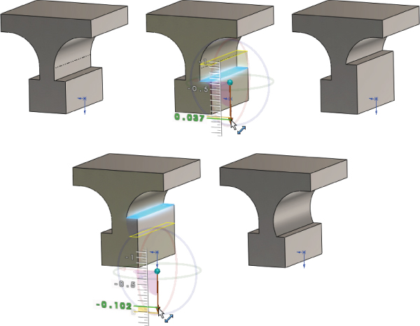
FIGURE 37.11 Editing limitations with direct editing
If you change the bottom square area such that the flat face between the bottom square and the arc disappears, you cannot get it back by just moving the face back to where it was; you would have to move the face and then make a cut to reinstate the flat face. This limitation is less serious when the Direct Editing tool is just another tool within a history-based modeler, because you can resort to the more powerful history-based tools to compensate, but with a dedicated direct-editing-only tool, you'll be up against a more difficult task.
Other limitations of direct-editing-only CAD software “have to do with” or “are related to” features that themselves are some sort of process, such as fillets or shells or extruded sketch text. Although fillets and shells are two of the most problematic features for history-based modeling, they are also two features that create the biggest limitations for direct-editing software.
Using SolidWorks Direct Editing Tools
So how does SolidWorks, a history-based system, incorporate the advantages of direct-editing techniques, which are not typically thought of as history-based? What does it look like when contradictory regimes collide and start sharing ideas? SolidWorks has taken ideas from a history-free scheme and incorporated them into a history-based scheme.
First, I'll show you how this works in a simple example. Using the part from Figure 37.11, Figure 37.12 shows the FeatureManager and the original sketch. Notice that the original sketch hasn't changed, but the part itself has. Rolling back eliminates the Move Face features, and making changes to the original sketch changes the starting points for the Move Face features when they are unrolled.
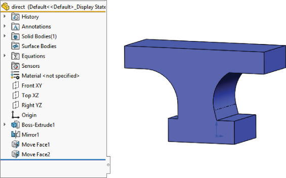
FIGURE 37.12 Direct edits in a history-based part
You may be able to imagine that in a part with a much longer feature tree, where the relationships between the faces and the features are more complex, overriding that complexity by editing a face directly could have some appeal.
Using Move Face
When it comes down to it, the direct-editing capabilities in SolidWorks are primarily represented by the Move Face feature. There are other features like Delete Face, and some of the body transformation tools, but Move Face is the primary tool.
Move Face enables you to move (offset, rotate or translate) a selection of faces that does not have to correspond to any features. They don't even have to connect. As long as translating or rotating the selected faces can work by extending or trimming neighboring faces, Move Face will probably work. The limitations that most often cause Move Face edits to fail are tangencies that can't be extended or situations that require a new face to be created.
For example, Figure 37.13 shows the top section of the imported rivet being moved by the Move Face tool. It required the selection of 48 faces to do this, dragging along the graphical interface.
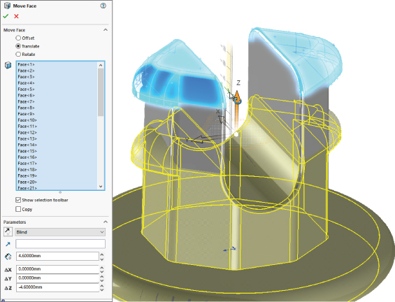
FIGURE 37.13 The Move Face tool in action
Because this is imported geometry, and the edit is something other than a cut or added geometry, Move Face and direct edit are really something different and extremely powerful. To work this way, you need to have an intuitive grasp of the NURBS or BREP model. You don't have to worry about which faces are controlled by which features, or which sketch drives which feature; you just select the faces you want to change and tell the software how you want to change them. At least that is the concept in traditional direct-editing software. But as I mentioned earlier, SolidWorks is not traditional direct-editing software; it’s a history-based modeler. SolidWorks can still do this edit, but in true history-based modeling fashion, it has to record the edit as a feature, which a true direct editor would not do. This is the main conflict when it comes to SolidWorks and direct editing. SolidWorks can do some of the direct-editing functions, but it does so in a very nondirect-edit sort of way.
Combining Direct Editing with History
SolidWorks has several features that don't create new geometry; they edit existing geometry only, whether it's native or imported. These include the tools from the Direct Editing tab of the CommandManager, shown in Figure 37.14.

FIGURE 37.14 The tools from the Direct Editing tab of the CommandManager
I'll show you a slightly more complex example. In traditional SolidWorks usage, if you wanted to move the face indicated in Figure 37.15, you would go back and edit the sketch or feature that was used to create it. That would be easy enough, and the fillets would update to match the new geometry.
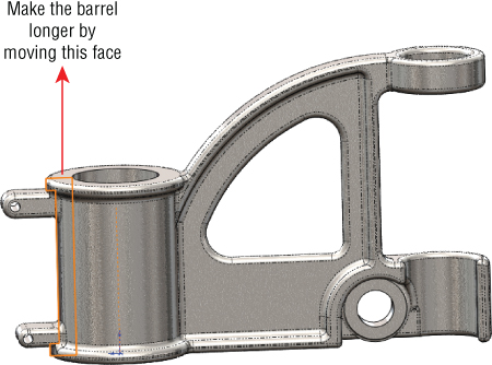
FIGURE 37.15 Fillets greatly complicate direct-editing schemes.
A proponent of direct-editing software would say that first finding the feature you need to change is difficult, and then waiting to unbuild the model back to that sketch, then waiting for the change to rebuild all the features after the sketch is complete, and finally dealing with the downstream features like fillets that might fail due to the changes is frustrating—and he would be right. (You can find a feature in the tree by right-clicking geometry in the graphics window and selecting Go To Feature In Tree.) The problem is that the part, as shown in Figure 37.15, cannot be changed at all in the traditional direct-editing scheme. In the direct-editing scheme, the fillets are just faces; they aren't intelligent features. If you move faces they are attached to, you have to also explicitly tell the fillet faces what to do.
While the direct-editing implementation in software such as Solid Edge is smart enough to make changes to models with fillets on them, the Direct Editing tools in SolidWorks are less sophisticated and cannot deal with the fillets at all.
Here's how to simplify the part by suppressing fillets and using the Move Face feature to change the part (see Figure 37.16). In order to do this, you will have had to make sure that no fillet features have children other than other fillet features. Here, I've suppressed the fillets and moved the ring around the top of the barrel as well as the mounting boss.
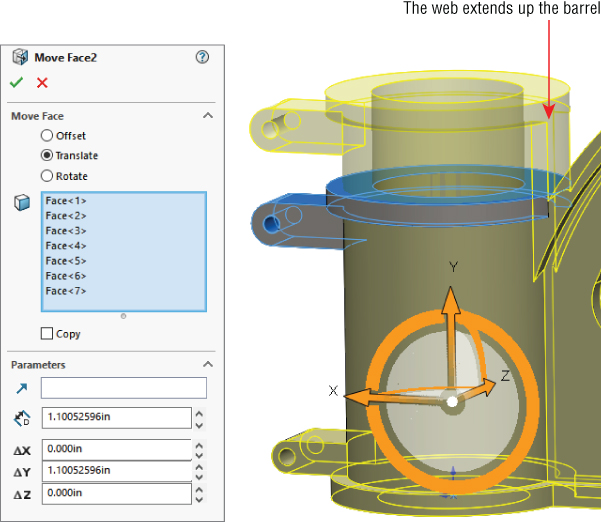
FIGURE 37.16 Using Move Face to extend the length of the barrel of the cast part after the fillets have been removed
In order to make this move, I had to select seven faces:
- Top of the ring
- Bottom of the ring on the left
- Bottom of the ring on the right
- Top of the boss
- Bottom of the boss
- Full round on the end of the boss
- Hole in the mounting boss
Notice how the web now extends up the side of the barrel. This is the type of edit that would be clumsy in SolidWorks history-based tools if it were what you wanted to do. In direct edit, it's the kind of edit that would be clumsy if it were not what you wanted to do.
This is one of the limitations of direct-editing techniques in general—not a limitation of SolidWorks, but a limitation of the concept as implemented in SolidWorks.
Figure 37.17 shows where the weakness of using the Direct Editing tools within SolidWorks begins to show up. The first feature in the part is a revolve that uses a sketch. The last feature in the part is a Move Face feature that moves the faces created by the revolve. So, if you want to change the geometry of the barrel, it's controlled by two different features. If you make the sketch a specific size, the Move Face feature changes it. Move Face can change only relative to a starting point; it cannot make something a specific dimension.
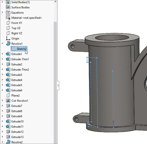
FIGURE 37.17 The Move Face features put some geometry in double jeopardy because it can be changed from two different places.
Some SolidWorks power users consider this double-jeopardy condition sloppy design or bad practice. You can make a strong case that the Direct Editing tools should not be used on native SolidWorks parts and that you should edit the feature the way it was created. There is certainly a place for that argument. But I know from my own modeling work that sometimes changing a feature way back in the tree can have unintended repercussions later in the tree, just due to the limitations of history-based modeling. Using a Move Face feature late in the tree avoids fixing lots of propagated errors. Is that a cheap, sleazy cheat? You will have to decide that for yourself.
Combining Direct Editing with Imported Geometry
Regardless of any argument against using Direct Editing tools on native SolidWorks data, there can be no such argument against using them on imported data. Direct Editing tools may have their limitations, but when dealing with imported geometry in SolidWorks, your choices are limited, as you see from the following:
- Direct Editing tools
- Cut and add modeling
- Manual Surfacing tools
- FeatureWorks deconstruction
When faced with these options, Direct Editing tools look like the safe choice. The big problem is that, if the part is covered with fillets, you may not be able to change much. In cases like that, you might use a combination of tools, such as FeatureWorks to remove fillets, and then directly edit to make changes.
Tutorial: Importing and Repairing Solid Geometry
This tutorial walks you through the button clicks to import CAD data from IGES and make some edits:
- From the download data, open the file called
cover.igs. You can open this file by selecting it in the Open dialog box (File ➢ Open) or by dragging and dropping it from Windows Explorer. - Right-click the Imported1 feature and run Import Diagnosis. Notice that Import Diagnosis finds no errors on the part.
- Look at the inside of the part, in the area near the part origin, and notice that, on one end of the tab, all the fillets come to a point, as shown in Figure 37.18. This is clearly not right, although Import Diagnosis didn't identify it as a problem.

FIGURE 37.18 A corner where three fillets come together isn't correct.
- Open a sketch on the flat face from which the tab protrudes. Right-click any edge where the tab intersects the sketch face and select Select Tangency. Then click the Convert Entities toolbar button, click the green checkmark icon to accept the result, and exit the sketch.
- Right-click one of the long faces of the tab and select Select Tangency. This selects all but two faces of the tab. There are 16 faces altogether. Activate the Delete Face feature, select the Delete and Patch option, select the two remaining faces of the tab, and accept the result. The model should remain a solid model, and the tab should be replaced by a smooth face.
- Select the sketch created in step 4 and extrude it to a blind depth of 0.050 inch. Apply a fillet around the end face with a radius of 0.010 inch.
- Activate the Move Face feature. Select all the faces of the two side tabs and the Snap feature on the end. Use the Translate option and the Right (YZ) plane as the direction and use a distance of 0.25 inch. You should have no less than 21 faces selected. Faces that are parallel to the translate direction don't need to be selected, because they're automatically extended or trimmed to fit. If you're having trouble selecting the right faces, refer to Figure 37.19 and open the finished part from the download materials on the website called
Tutorial1finished.sldprt.
FIGURE 37.19 Moving tabs and Snap in a single Move Face feature
- Save the part under a different name and exit.
Tutorial: Flex and Freeform
This tutorial steps you through importing and editing geometry using the Move Face, Flex, and Freeform features in SolidWorks:
- Open the Parasolid file from the Wiley website called
ellipse.x_t. - Increase the size of the part by using the Move Face feature with the Offset option. You can enter the offset distance in the appropriate field of the PropertyManager. Use an offset distance of about 0.08 inch. Make sure only the elliptical face of the model is selected.
- Activate the Flex feature and use the following settings (as shown in Figure 37.20):

FIGURE 37.20 Using Flex Bending to bend an imported part
- Select the body in the graphics window in the top selection box.
- Select the Bending option in the Flex Input section.
- Select Hard Edges in the Flex Input section.
- Select 190deg for the angle.
- In Trim Plane 1, set the distance to 48.26 millimeters (or 1.9 inches).
- In Trim Plane 2, set the distance to 114.3 millimeters (or 4.5 inches).
- Open a sketch on the Front (XY) plane, orient the view normal to it, and then sketch an ellipse with one end of the major axis at the origin and the rest dimensioned, as shown in Figure 37.21.

FIGURE 37.21 Sketching an ellipse
- Initiate a split line (Insert ➢ Curves ➢ Split Line) and select the bent face of the part. Accept the feature when you are finished.
 Initiate a Freeform feature and select the elliptical split face on the outside of the bend created by the Flex feature. Click the Direction 1 Symmetry option, and a gray plane should appear along the Right (YZ) plane.
- Click the Add Curves button, snap the cursor to the Symmetry plane and click to add a curve. The Symmetry plane will highlight orange when it's selected. Add a second curve parallel to the first one about one-third of the way from the Symmetry plane to the edge of the split.
- Click the Add Points button and place a point approximately as shown in Figure 37.22. Place a point on the second curve in approximately the same location as the first point. Figure 37.22 shows one point on each curve. Click the Add Points button to deselect it when you are finished.
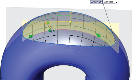
FIGURE 37.22 Locating a point
- Change the Continuity flag pointing to the edge of the split from Contact to Curvature.
- Click the curve on the Symmetry plane, and then click the point on that curve. Drag the arrow handle to pull the point away from the part approximately as shown in Figure 37.23.
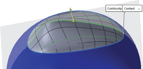
FIGURE 37.23 Pulling the point to create a freeform shape from the existing face
- Click the second curve, and then click and move the second point in a way similar to the first point. When you are finished, the part should look similar to Figure 37.24.
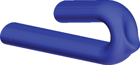
FIGURE 37.24 The finished freeform surface
- Save the file using a different name.
The Bottom Line
In recent years, Direct Editing tools have received lots of hyped press and marketing attention. However, CAD tools dedicated to working primarily as Direct Editing tools aren't going to overtake the tools used by professionals who design and model for production. If anything, they'll be used primarily by non-CAD specialists for simple editing and simple concept development, and possibly by downstream data consumers such as FEA analysts or CNC (Computer Numerical Control) machinists.
The Direct Editing tools available within SolidWorks are powerful and are becoming more powerful with each release. Although they may be best applied to imported data, they can also be applied to native SolidWorks data. This brings up questions of best practice and duplication of effort. Sometimes, the changes involved in editing a feature near the top of a long feature tree can be time-consuming compared to simply moving a couple of faces.
- Master It Familiarize yourself with existing import and export options. Use a model without errors for practice. If you have another CAD package available to you, use that for practice as well.
- Master It Open an assembly from one of the chapters on assemblies and export it. Then import it to see how it behaves and what you get. The practice of export/import is called a round trip. It is one way you can verify that the software has written good output data.
Be aware that importing an assembly will save automatically named part files on your hard drive. Make sure that the filenames are not overwriting or causing conflicts with other part files.
- Master It The direct editing features are
- Move Face
- Delete Face
You can also perform any function that affects bodies rather than features.
Take the
Chapter 37 - casting direct edit.sldprtpart and practice removing fillets (using the Delete Face feature with the Delete and Patch option) without using any history-based tricks like rolling back or suppressing. Start with a simple loop like the filleted edges of the pie-shaped cut out in the web of the part.Remember that unlike true direct-editing CAD tools, SolidWorks leaves a history-based feature every time you use the Delete Face.