
Chapter 1
Introducing SolidWorks
In SolidWorks, you build 3D parts from a series of simple 2D sketches and features such as extrude, revolve, fillets, cuts, and holes, among others. You can put the parts together into assemblies. You can then create 2D drawings from the 3D parts and assemblies.
This chapter will familiarize you with some of the basic concepts employed by SolidWorks.
Installing SolidWorks for the First Time
Some of you will have SolidWorks installed for you by people in your company or by SolidWorks reseller experts, and some of you will need to perform the installation on your own. Regardless, it is best to make sure that your hardware and software are compatible with the SolidWorks system requirements, which are available on the SolidWorks website at www.solidworks.com/sw/support/SystemRequirements.html.
SolidWorks installs natively only on 64-bit operating systems. It is supported only for Windows 7, 8.1, and 10. In all cases, the professional-level OS is recommended, as opposed to the Home edition. Excel and Word 2016 are also recommended. Although it is possible to install and run SolidWorks under emulators on Apple hardware, that configuration is not supported or tested by SolidWorks Corporation or its resellers.
You can find graphics card requirements at the previously mentioned link for system requirements. The main concern with a graphics card for SolidWorks is that it must be compatible with OpenGL and be SolidWorks certified. Hardware changes too rapidly for me to give specific recommendations here.
In addition to having the correct hardware installed, you also must have a compatible driver version installed. Again, refer to the SolidWorks system requirements website.
Alternatively, you might not want to get that involved at first. You can install the software with all the defaults just to get started, using the first attempt as a practice installation, especially if you intend to learn as much as you can about SolidWorks, and then come back and do a more thorough job of implementing it later.
You should count on the installation requiring about 16 GB of space on your hard drive, depending on the options you select to install. The locations of files on your computer will vary by SolidWorks version, by your operating system, and by your own installation choices, but the bulk of the files will be placed into two separate folders: the Program Files folder (C:Program FilesSolidWorks CorpSolidWorks) and the Toolbox Data folder (C:SolidWorks Data).
Before installing any software, be sure to exit out of all other software first, turn off antivirus software, make sure you have enough hard drive space, and verify that the system meets the requirements outlined on the SolidWorks System Requirements web page.
Installations generally begin from a download of an installer application named SolidWorksSetup.exe, which is about 30 MB. You may need a login to access this area of the site. Find the download area at http://www.solidworks.com/sw/support/downloads.htm, shown in Figure 1.1.
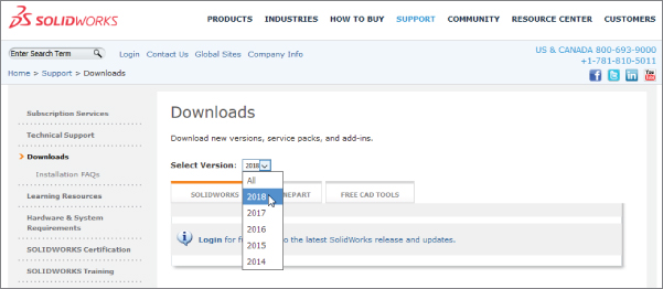
FIGURE 1.1 The Downloads area of the SolidWorks website
Once you download and execute the installer, you will be prompted to unzip the installation files, and the installation will begin, as shown in Figure 1.2.

FIGURE 1.2 The SolidWorks 2018 Installation Manager
The next screen asks for your serial number, which is a 24-character code. After the installation, you will be required to activate your SolidWorks license. Figure 1.3 shows the Activation page of the installation process. If you have difficulty with this, you may want to contact your support organization.

FIGURE 1.3 SolidWorks 2018 Activation
When the installation is complete, reboot the system.
Starting SolidWorks for the First Time
SolidWorks has many tools that are available for beginning users when the software is installed. A default installation presents you with several options when the software is started the first time. This section includes a description of these options and how you can most benefit from them. If you plan to go to formal SolidWorks reseller-based training classes, be sure to go through some of the tutorials mentioned in this section first, so you will be prepared to ask educated questions and have a leg up on the rest of the class. You will get more out of the training with the instructor if you have already seen the material.
Examining the SolidWorks License Agreement
Becoming familiar with the license agreement can be useful, but the agreement does not have any bearing on learning how to use the software other than the fact that it allows you to reactivate as needed. This ability enables you to use your license on different computers—for example, at work and at home. To use your license at home, make sure the software is installed at both locations and both locations are connected to the Internet, and then activate it at work. When you are done at work, deactivate the license and reactivate it at home using the same serial number. It would be a good idea to consult your CAD administrator before you do this. You can access the Activation options in the Help menu, as shown in Figure 1.4. Network licenses may work differently. When you are done at home, you can deactivate the license at home and reactivate at work. It is like a floating license, where the server is at a SolidWorks facility. Again, contact your support organization with questions about any specific details.

FIGURE 1.4 Activation options on the Help menu
Using the Help Menu
You can access the Help menu in two ways. A question mark in the upper right has a drop-down arrow next to it that enables you to access all the Help options. Help is also on the flyout menu next to the SolidWorks logo in the upper left. You will find that SolidWorks offers multiple ways to access many commands. You should become comfortable with at least one method for accessing the tools you need to use. It isn't necessary to know all the ways unless you are teaching others (or writing a book).
VIEWING THE WELCOME TO SOLIDWORKS DIALOG
The Welcome to SolidWorks screen, shown in Figure 1.5, is the first thing to greet you when you open the software. This helps you open recent files, browse for existing data, or create a new document. The Advanced button gives you access to all available templates (templates will be covered later in this chapter), and you can look inside the folders for each of the recent documents by hovering the mouse cursor over the preview.
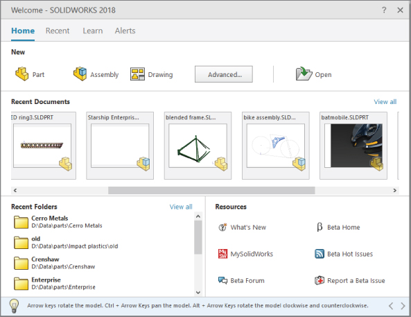
FIGURE 1.5 The Welcome to SolidWorks screen
The tabs at the top of the dialog (Home, Recent, Learn, and Alerts) will reconfigure the Welcome dialog to show various topics. The Learn tab has links to various training and tutorial material, sample parts, and assemblies. The Alerts tab shows SolidWorks news such as the release of a Beta or special notices about problems or fixes in the software.
Also notice at the bottom of the Welcome dialog is the Tip of the Day. You can cycle through these tips when you have a few spare moments.
ACCESSING WHAT'S NEW
You can find the What's New documentation in the Help menu, as shown in Figure 1.4. You can also enable interactive What's New options (Help ➢ What's New ➢ Interactive). This adds a question mark with an asterisk symbol next to menu items that are new and have special Help file entries. You will find more information about setting up the SolidWorks interface in Chapter 2, “Navigating the SolidWorks Interface.”
ACCESSING OTHER RESOURCES
Between the Help and the Welcome dialogs, SolidWorks offers several options for help, including tutorials, What's New, and the SolidWorks forums.
Creating a New Document
![]() To start a new SolidWorks document, click the New icon in the title bar of the SolidWorks application. With standard functions such as creating a new document, SolidWorks works just like a Microsoft Office application, and the icons even look the same.
To start a new SolidWorks document, click the New icon in the title bar of the SolidWorks application. With standard functions such as creating a new document, SolidWorks works just like a Microsoft Office application, and the icons even look the same.
SolidWorks has three basic types of documents: parts, assemblies, and drawings. Parts are the basic 3D file type. You put parts together to create assemblies, and drawings are the 2D file type for documenting parts and assemblies.
When you create a new SolidWorks document, you will see the screen shown in Figure 1.6. By default, this dialog box contains templates for parts and assemblies. You can make your own customized templates to add to them or share templates with other users on a network. Templates have several already-established settings, most importantly units. You can change the units of a document after it is created, but most people find it easier to start with the correct units. You can mix units in parts, and used parts with different units in assemblies, but this can get confusing when editing parts with mixed units in the context of an assembly.
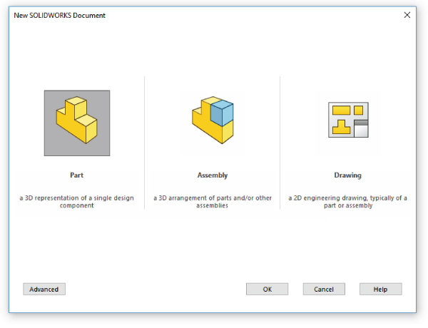
FIGURE 1.6 Selecting a template in the New SolidWorks Document dialog
Templates also control the drafting standard used with the document. ANSI and ISO are the two primary standards, although others are available. One option you need to be aware of with the ISO standard is that some locations that use the ISO standard also use First Angle Projection, while ANSI users and some ISO users use the Third Angle Projection system.
The Drafting Standard setting is found under Tools ➢ Options ➢ Document Properties ➢ Drafting Standard, as shown in Figure 1.7. The projection angle can be specified both in drawings and in parts/assemblies. You can find the drawing setting by clicking the right mouse button (RMB), clicking on the Sheet entry in the FeatureManager on the left of the drawing document window, and selecting Sheet Properties.
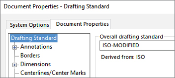
FIGURE 1.7 Drafting Standard setting
The projection type for 3D parts and assemblies becomes important when you set up viewports within the SolidWorks window. The setting for this is located under Tools ➢ Options ➢ Display/Selection ➢ Projection type (at the bottom of the list). This does not follow the drafting standard selected for the default templates or the country in which the software is installed.
For more information on first- and third-angle projections, refer to this Wikipedia article: http://en.wikipedia.org/wiki/Multiview_orthographic_projection.
Be sure to get the option correct. If someone else, such as a computer specialist who is not familiar with mechanical drafting standards, initially sets up SolidWorks on your computer, verify that the default templates use the correct standards, units, and projection method. The projection angle setting is shown in Figure 1.8.

FIGURE 1.8 Projection Angle setting
Identifying SolidWorks Documents
SolidWorks has three main data type files: parts, assemblies, and drawings; however, if you are concerned with customizing and creating implementation standards, you may want to become familiar with some additional supporting types. Table 1.1 outlines the document types.
TABLE 1.1: Document Types
| DESIGN DOCUMENTS | DESCRIPTION |
.sldasm |
SolidWorks assembly file type |
.slddrw |
SolidWorks drawing file type |
.sldprt |
SolidWorks part file type |
| Templates and Formats | Description |
.asmdot |
Assembly template |
.asmprp |
Assembly custom properties tab template |
.drwdot |
Drawing template |
.drwprp |
Drawing custom properties tab template |
journal.doc |
Design journal template |
.prtdot |
Part template |
.prtprp |
Part custom properties tab template |
.sldbombt |
BOM template (table-based) |
.sldtbt |
General table template |
.slddrt |
Drawing sheet format |
.sldholtbt |
Hole table template |
.sldrevtbt |
Revision table template |
.sldwldtbt |
Weldment cutlist template |
.xls |
BOM template (Excel-based) |
| Library Files | Description |
.sldblk |
Blocks |
.sldlfp |
Library part file |
| Styles | Description |
.sldgtolfvt |
Geometric tolerance style |
.sldsffvt |
Surface finish style |
.sldweldfvt |
Weld style |
| Symbol Files | Description |
gtol.sym |
A symbol file that enables you to create custom symbols |
swlines.lin |
A line-style definition file that enables you to create new line styles |
| Others | Description |
.btl |
Sheet metal bend table |
calloutformat.txt |
Hole-callout format file |
.sldclr |
Color palette file |
.sldreg |
SolidWorks settings file |
.sldmat |
Material database |
.sldstd |
Drafting standard |
.swb, .swp |
Macros, macro features |
.txt |
Custom property file, sheet-metal-bend-line note file |
.xls |
Sheet metal gauge table |
Unlike some other CAD programs, SolidWorks does not use separate file types for sheet metal and weldment parts; they are all just *.sldprt. The features within the parts distinguish them as either sheet metal or weldment parts.
Also unlike other CAD programs, SolidWorks' templates have a special file type (for example, part templates are *.prtdot) and are not just “start parts.”
Saving Your Setup
If you need to reinstall SolidWorks, move to another computer, or duplicate the setup for another user, you need to copy the files you have used or customized. By default, all these files are located in different folders within the SolidWorks installation directory. Chapter 2 deals with interface settings and creating a Registry Settings file to copy to other computers or use as a backup.
Using Templates
I have included some of my part and assembly templates with the download materials for this book. After you have downloaded the zip files for each chapter, extract and copy them to the folder specified at Tools ➢ Options ➢ File Locations ➢ Document Templates.
When you begin to create a new document, and the New SolidWorks Document dialog box gives you the option to select one of several files to start from, those files are templates. Think of templates as “start parts” that contain all the document-specific settings for a part (Tools ➢ Options ➢ Document Properties). The same concept applies to assemblies and drawings. Templates generally do not have any geometry in them (although it is possible).
As shown in Figure 1.6, several tabs can be displayed on the Advanced interface. Each of these tabs results from creating a folder in the template directory specified in the Options dialog box (Tool ➢ Options ➢ File Locations ➢ Document Templates). To switch from the Novice interface to the Advanced interface, click the Advanced button. To switch from Advanced to Novice, click the Novice button shown in Figure 1.9.

FIGURE 1.9 The Novice and Advanced interfaces for the New SolidWorks Document dialog box
MULTIPLE DOCUMENT TEMPLATES
When starting a new document, you will be given many options if you have multiple templates available. This offers an advantage in many situations, including the following:
- Standardization for a large number of users
- Work produced in various units
- Preset materials
- Preset custom properties
- Parts with special requirements, such as sheet metal or weldments
- Parts and assemblies with standardized background colors
- Drawings of various sizes with formats (borders) already applied
- Drawings with special notes already on the sheet
Drawing templates and formats are so complex that I devote an entire chapter to them. Chapter 24, “Automating Drawings: The Basics,” discusses the differences between drawing templates and formats, and how to use them to your advantage. This chapter addresses part and assembly templates.
Depending on your needs, it might be reasonable to have templates for metric parts and assemblies and Imperial parts and assemblies, templates for steel and aluminum, and templates for sheet metal parts and weldments, if you design these types of parts. If your firm has different customers with different requirements, you might consider using separate templates for each customer. Over time, you will discover the types of templates you need, because you will find yourself repeatedly making the same changes to new parts.
To create a template, open a document of the appropriate type (part, assembly, or drawing), delete all features. (Although it is possible to use templates with pre-created geometry, it is unusual.) Make the settings you want the template to have. For example, units are one of the most common reasons to make a separate template, although any Document Property setting is fair game, from the dimensioning standard used to the image quality settings. You can find these settings through the menus at Tools ➢ Options➢ Document Properties.
Some document-specific settings do not appear in the Document Properties dialog box, such as the names of standard planes or the use of axes as reference geometry. Still, these settings are saved with the template. Settings that fall into this category are the View menu's entity-type Visibility option and the Tools ➢ Sketch Settings menu options.
Custom properties are another piece of the template puzzle. If you use or plan to use BOMs (Bills of Materials), PDM (Product Data Management), or linked notes on drawings, you need to take advantage of the automation options available with custom properties.
Two Default Template options are available: “Always use these default document templates” and “Prompt user to select document template.” The Default Template options apply to situations when a template is required by an automatic feature in the software, such as an imported part or a mirrored part. In this situation, depending on the option selected, the system automatically uses the default template or the user is prompted to select a template.
SHARING TEMPLATES
If you are administering an installation of a large number of users, or even if just a couple of users are working on similar designs, shared templates are necessary. If every user does what he or she thinks is best, you may get an adverse combination of conflicting ideas, and the consistency of the company's documentation may suffer. Standardized templates cannot make users model, assemble, and detail in exactly the same way, but they do help users start on the same foot.
To share templates among several users, create a folder for templates on a commonly accessible network location, preferably with read-only access for users and read-write permissions for administrators. Then point each user's File Locations and Default templates to that location. Access problems due to multiple users accessing the same files do not arise in this situation, because users copy templates to create new documents and do not use them directly.
Understanding Feature-Based Modeling
Before diving into building models with SolidWorks, you need to be familiar with some terminology. Notice that I talk about modeling rather than drawing or even design. Whether you are building an assembly line for automotive parts or designing decorative perfume bottles, SolidWorks can help you visualize your geometrical production data in the most realistic way possible without actually having it in your hand. This is more akin to making a physical model in the shop than drawing on paper.
Feature-based modeling means that you build the model by creating 2D sketches and applying processes (features) to create the 3D shape. For example, you can create a simple box by using the Extrude process, and you can create a sphere using the Revolve process. However, you can make a cylinder using either process, by revolving a rectangle or extruding a circle. Figure 1.10 shows images of simple feature types along with the 2D sketches from which they were created.
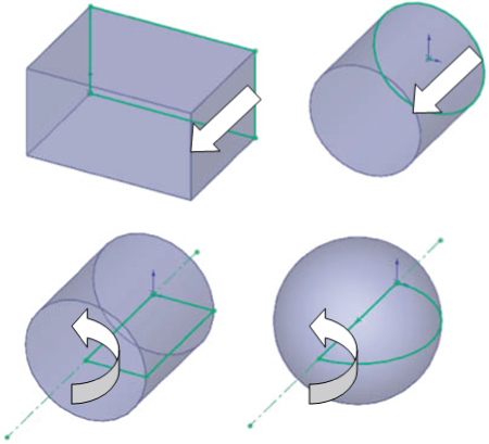
FIGURE 1.10 Simple extruded and revolved features
Many different feature types in SolidWorks enable you to create everything from the simplest geometry shown in Figure 1.10 to more complex shapes. In general, when I talk about modeling in this book, I am talking about solid modeling, although SolidWorks also has a complete complement of surfacing tools. I discuss the distinction between solid and surface modeling in Chapter 32, “Working with Surfaces.”
Table 1.2 lists some of the most common features in SolidWorks and classifies them according to whether they always require a sketch, a sketch is optional, or they never require a sketch. As an example of a sketch optional feature, a sweep can use a model edge as a sweep path.
TABLE 1.2: Feature Types
| Sketch Required | Sketch Optional (uses faces or edges) | NO SKETCH (APPLIED FEATURES) |
| Extrude | Loft | Fillet |
| Revolve | Sweep | Chamfer |
| Rib | Dome | Draft |
| Hole Wizard | Boundary | Shell |
| Wrap | Deform | Flex |
In addition to these features, other types of features create reference geometry, such as curves, planes, axes, and surface features (Chapter 32); specialty features for techniques like sheet metal (Chapter 34, “Using SolidWorks Sheet Metal Tools”); and plastics/mold tools (Chapter 38, “Using Plastic Features,” and Chapter 39, “Using Mold Tools”).
Understanding History-Based Modeling
In addition to being feature-based, SolidWorks is also history-based. The process history is shown in a panel to the left side of the SolidWorks window called the FeatureManager. The FeatureManager keeps a list of the features in the order in which you have added them. It also enables you to reorder items in the tree (in effect, to change history). Because of this, the order in which you perform operations is important. For example, consider Figure 1.11. This model was created by the following process, left to right starting with the top row:
- Create a sketch.
- Extrude the sketch.
- Create a second sketch.
- Extrude the second sketch.
- Create a third sketch.
- Extrude Cut the third sketch.
- Apply fillets.
- Shell the model.

FIGURE 1.11 Features used to create a simple part
If the operations used in the previous part were slightly reordered (by putting the shell and fillet features before Step 6), the resulting part would look slightly different, as shown in Figure 1.12. You can find this part in the download materials for this chapter.

FIGURE 1.12 Using a different order of features for the same part
Figure 1.13 shows a comparison of the FeatureManager design trees for the two different feature orders. You can reorder features by dragging them up or down the tree. However, relationships between features can prevent them from being reordered; for example, the fillets are dependent on the second extruded feature and cannot be reordered before it. This is referred to as a parent/child relationship.

FIGURE 1.13 Comparing the FeatureManager design trees for the parts shown in Figure 1.11 and Figure 1.12, respectively
Reordering and parent/child relationships are discussed in more detail in Chapter 12, “Editing, Evaluating, and Troubleshooting.”
The order of operations, or history, is important to the final state of the part. For example, if you change the order so that the shell comes before the extruded cut, the geometry of the model changes, removing the sleeve inside instead of the hole on top. You can try this for yourself by opening the part indicated previously, dragging the Shell1 feature in the FeatureManager and dropping it just above the Cut-Extrude1 feature.
You can read more about reordering folders in Chapter 12.
In some cases, reordering the features in the FeatureManager can have a result that does not make any sense; for example, if the fillets are applied after the shell, they might break through to the inside of the part. In these cases, SolidWorks gives an error that will help you fix the problem.
Features are really just like steps in building a part; the steps can add material, remove it, or both. However, when you make a part on a mill or lathe, you are only removing material. Some people choose to model following manufacturing methods, so they start from a piece of stock and apply features that remove material, as you would on a mill. This approach works best for machining, but doesn't work well for molding, casting, sheet metal, or progressive dies. The FeatureManager is like an instruction sheet to build the part. When you reorder and revise the list of features, you change the order of operations and thus the final result. Some people look at the FeatureManager as a recipe for cooking.
Sketching with Parametrics
Sketching is the foundation that underlies the most common feature types. You will find that sketching in parametric software is vastly different from drawing lines in 2D CAD.
Dictionary.com defines the word parameter as “one of a set of measurable factors … that define a system and determine its behavior and [that] are varied in an experiment.” SolidWorks sketches are parametric. What this means is that you can create sketches that change according to certain rules and maintain relationships through those changes. Creating sketches and features with intelligence is the basis of the concept of design intent, which I cover in more detail later in this chapter.
In addition to 2D sketching, SolidWorks also makes 3D sketching possible. Of the two methods, 2D sketches are by far more widely used. You create 2D sketches on a selected plane or planar face and then use them to establish shapes for features such as Extrude, Revolve, and others. Relations in 2D sketches often are created between sketch entities and other model edges that may or may not be in the sketch plane. In situations where other entities are not in the sketch plane, the out-of-plane entity is projected into the sketch plane in a direction that is normal to the sketch plane. This does not happen for 3D sketches.
You can use 3D sketches for the Hole Wizard, routing, weldments, and complex shape creation, among other applications.
For more information on 3D sketching, refer to Chapter 6, “Getting More from Your Sketches.”
For a simple example of working with sketch relations in a 2D sketch, consider the sketch shown in Figure 1.14. The only relationships among the four lines are that they form a closed loop that is touching end-to-end and one of the corners is coincident to the part origin. The small square icon near the origin shows the symbol for a coincident sketch relation. These sketch relations are persistent through changes and enable you to dynamically move sketch elements with the cursor on the screen. The setting to enable or disable displaying the sketch relation symbols is found at View ➢ Sketch Relations.
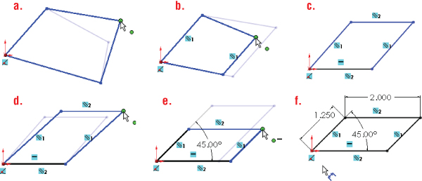
FIGURE 1.14 A sketch of four lines changes as relationships and dimensions are added.
If you drag any of the unconstrained corners (except for the corner that is coincident to the origin), the two neighboring lines follow the dragged endpoint, as shown in Figure 1.14. Notice the ghosted image left by the original position of the sketch. This is helpful when you’re experimenting with changes to the sketch because you can see both the new and the old states of the sketch. The setting to enable or disable this ghosted position is found at Tools ➢ Options ➢ Sketch ➢ Ghost Image On Drag.
If you add a parallel relation between opposing lines, they now act differently, as shown in Figure 1.14. You add a parallel relation by selecting the two lines (Ctrl + Select) to make parallel and selecting Parallel from the context toolbar or the PropertyManager panel.
You can read more about the PropertyManager in Chapter 2.
Next, add a second parallel and a horizontal relation, as shown in Figure 1.14. If you are following along by re-creating the sketch on your computer, you will notice that one line has turned from blue to black.
The line colors represent sketch states. It may be impossible to see this in the black-and-white printing of this book, but if you are following along on your own computer, you should see one black line and three blue lines. Sketch states include Underdefined, Overdefined, Fully Defined, Unsolvable, Zero Length, and Dangling, and they are described as follows:
- Blue: Underdefined The sketch entity is not completely defined. You can drag a portion of it to change size, position, or orientation.
- Black: Fully Defined The sketch entity is fully defined by a combination of sketch relations and dimensions. A sketch cannot be fully defined without being connected in some way to something external to the sketch, such as the part origin or an edge. (The exception to this rule is the use of the Fix constraint, which, although effective, is not a recommended practice.)
- Red: Overdefined—Not Solved When a sketch entity has two or more relations and one of them cannot be satisfied, the unsatisfied relation will be red. For example, if a line has both Horizontal and Vertical relations, and the line is actually vertical, the Vertical relation will be yellow (because it is conflicting but satisfied), and the Horizontal will be red (because it is conflicting and not satisfied).
- Yellow: Overdefined—Conflicts Solving the sketch relations would result in a zero-length entity. For example, this can occur where an arc is tangent to a line, and the centerpoint of the arc is also coincident to the line.
- Brown: Dangling The relation has lost track of the entity to which it was connected.
Entities with different states can exist within a single sketch. In addition, endpoints of lines can have a different state than the rest of the sketched entity. For example, a line that is sketched horizontally from the origin has a coincident at one endpoint to the origin, and the line itself is horizontal. As a result, the line and first endpoint are black, but the other endpoint is underdefined because the length of the line is not defined. Sketch states are indicated in the lower-right corner of the graphics window and in the status bar. You can see that dragging one corner allows only the lines to move in certain ways, as shown in Figure 1.14.
In addition to sketch relations, dimensions applied using the Smart Dimension tool are also part of the parametric scheme. If you apply an angle dimension (by clicking the two angled lines with the Smart Dimension tool) about the origin and try dragging again, as shown in Figure 1.14, you see that the only aspect that is not locked down is the length of the sides. Notice also that when the angle dimension is added, another line turns black.
Finally, adding length dimensions for the unequal sides completes the definition of the sketch, as shown in Figure 1.14. At this point, all lines have turned black. This state is called “fully defined.” Between the dimensions and sketch relations, there is enough information to re-create this sketch exactly.
Parametric relations within a sketch control how the sketch reacts to changes from dimensions or relations within the sketch or by some other factor from outside the sketch. Other factors can drive the sketch as well, such as equations, other model geometry that is external to the sketch, and even geometry from another part in an assembly, as you'll see later.
Understanding Design Intent
Design intent is a phrase that you will hear often among SolidWorks users. I like to think of it as “design for change.” Design intent means that when you put the parametric sketch relations and dimensions together with the feature intelligence, you can build models that react to change in predictable ways. This gives you a great deal of control over changes.
An example of design intent could be a statement that describes general aspects that help define the design of a part, such as “This part is symmetrical, with holes that line up with Part A and thick enough to be flush with Part B.” From this description, and the surrounding parts, it is possible to re-create the part in such a way that if Part A or Part B changes, the part being described updates to match.
Some types of changes can cause features to fail or sketch relations to conflict. In most situations, SolidWorks has ample tools for troubleshooting and editing that you can use to repair or change the model. In these situations, it is often the design intent itself that is changing.
Editing Design Intent
One of the most prominent aspects of design in general is change. I have often heard it said that you may design something once, but you will change it a dozen times. You will find this to be true with both sketching and 3D modeling. Design intent is sometimes thought of as a static concept that controls changing geometry. However, design intent itself often changes, thus requiring the way in which the model reacts to geometric changes to also change. Fortunately, SolidWorks has many tools to help you deal with changing requirements.
Choosing Sketch Relations
The sketch relation symbols are the most helpful tools for visualizing design intent. You can show or hide icons that represent the relations by choosing View Sketch Relations from the Heads-Up View toolbar (or through the menus at View ➢ Hide/Show ➢ Sketch Relations). When shown, these relations appear as an icon in a small colored box in the graphics area next to the sketch entity. Clicking the icon highlights the sketch elements involved in that relation. Refer to Figure 1.15 for examples of these relations.
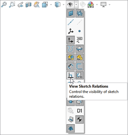
FIGURE 1.15 Turn on or turn off the display of sketch relations.
You can use the sketch relation icons on the screen to delete relations by selecting the icon in the graphics area and pressing Delete on the keyboard. You also can use them to quickly determine the status of sketch relations by referring to the colors defined earlier.
Selecting Display/Delete Relations
![]() The Display/Delete Relations tool enables you to list, sort, delete, and repair sketch relations. You can find the Display/Delete Relations tool on the Sketch toolbar. The sketch status colors defined earlier also apply here, with the relations appearing in the appropriate color. (Relations are not shown in blue or black, only the colors that show errors, such as red, yellow, and brown.) This tool also enables you to group relations by several categories:
The Display/Delete Relations tool enables you to list, sort, delete, and repair sketch relations. You can find the Display/Delete Relations tool on the Sketch toolbar. The sketch status colors defined earlier also apply here, with the relations appearing in the appropriate color. (Relations are not shown in blue or black, only the colors that show errors, such as red, yellow, and brown.) This tool also enables you to group relations by several categories:
- All In This Sketch
- Dangling
- Overdefining/Not Solved
- External
- Defined In Context
- Locked
- Broken
- Selected Entities
In the lower Entities panel of the Display/Delete Relations PropertyManager, shown in Figure 1.16, you can replace one entity with another or repair dangling relations.
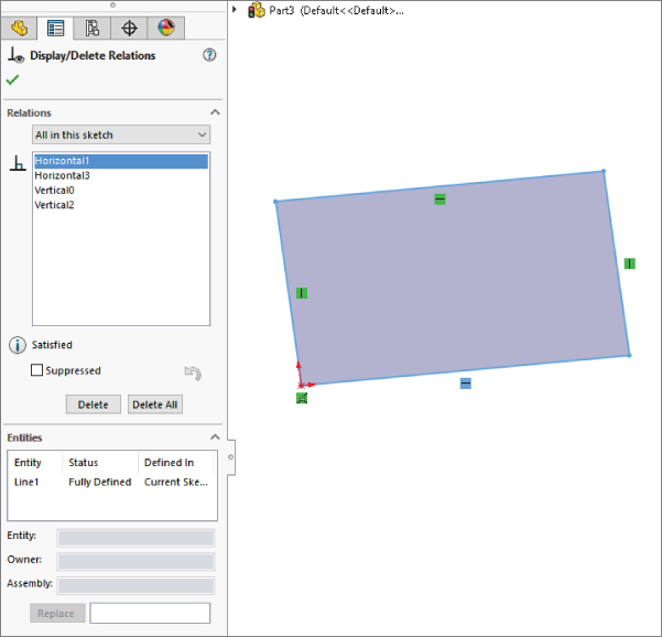
FIGURE 1.16 The Display/Delete Relations PropertyManager enables you to repair broken relations and replace entities.
You can read more about repairing dangling entities in Chapter 6.
Using Suppressed Sketch Relations
Suppressing a sketch relation means that the relation is turned off and not used to compute the position of sketch entities. Suppressed relations generally are used in conjunction with configurations. You can also suppress relations temporarily to resolve problems.
Configurations are discussed in detail in Chapter 11, “Working with Part Configurations.”
Working with Associativity
In SolidWorks, associativity refers to links between documents, such as a part that has an associative link to a drawing. If the part changes, the drawing updates as well. Bidirectional associativity means that the part can be changed from the part or the drawing document window. One of the implications of this is that you do not edit a SolidWorks drawing by simply moving lines on the drawing; you must change the 3D model, which causes all drawing views of the part or assembly to update correctly.
Other associative links include using inserted parts (also called base or derived parts), where one part is inserted as the first feature in another part. This might be the case when you build a casting. If the part is designed in its “as cast” state, it is then inserted into another part where machining operations are performed by cut features and the part is transformed into its “as machined” state. This technique is also used for plastic parts where a single shape spans multiple plastic pieces. A “master part” is created and split into multiple parts. An example would be a mouse cover and buttons.
One of the most important aspects of associativity is file management. Associated files stay connected by filenames. If a document name is changed and one of the associated files is not updated appropriately, the association between the files can become broken. For this reason, you should use either SolidWorks or SolidWorks Explorer to change the names of associated files.
The Bottom Line
Easy access to your tools cuts just seconds out of your work time every day, but a good habit will cut minutes, and several good habits can cut hours.
- Master It After SolidWorks has been installed as shown in this chapter, find the desktop icon, and put it on your taskbar or other easy-to-access interface element.
File organization is one of the keys to a successful SolidWorks implementation. While I don't expect you to have everything figured out at this stage in your learning, you need to start thinking about how to manage your SolidWorks libraries of templates and key features as well as your project data.
- Master It Make sure you know where the settings in Tools ➢ Options are located for identifying the locations for templates, and change this location if necessary.
One of the key concepts of managing SolidWorks is associativity. Data created in one file can be shown in another file. For example, part data is shown in both assemblies and drawings.
- Master It Open a SolidWorks drawing (
*.slddrw) and drag a SolidWorks part (*.sldprt) onto it. Make a change to the part and watch it update on the drawing.